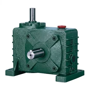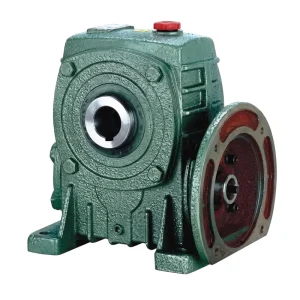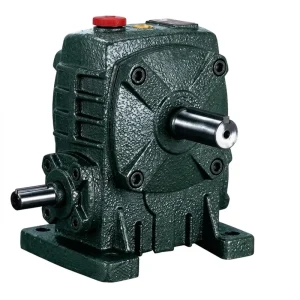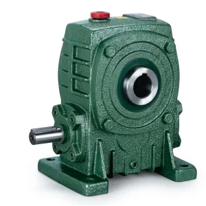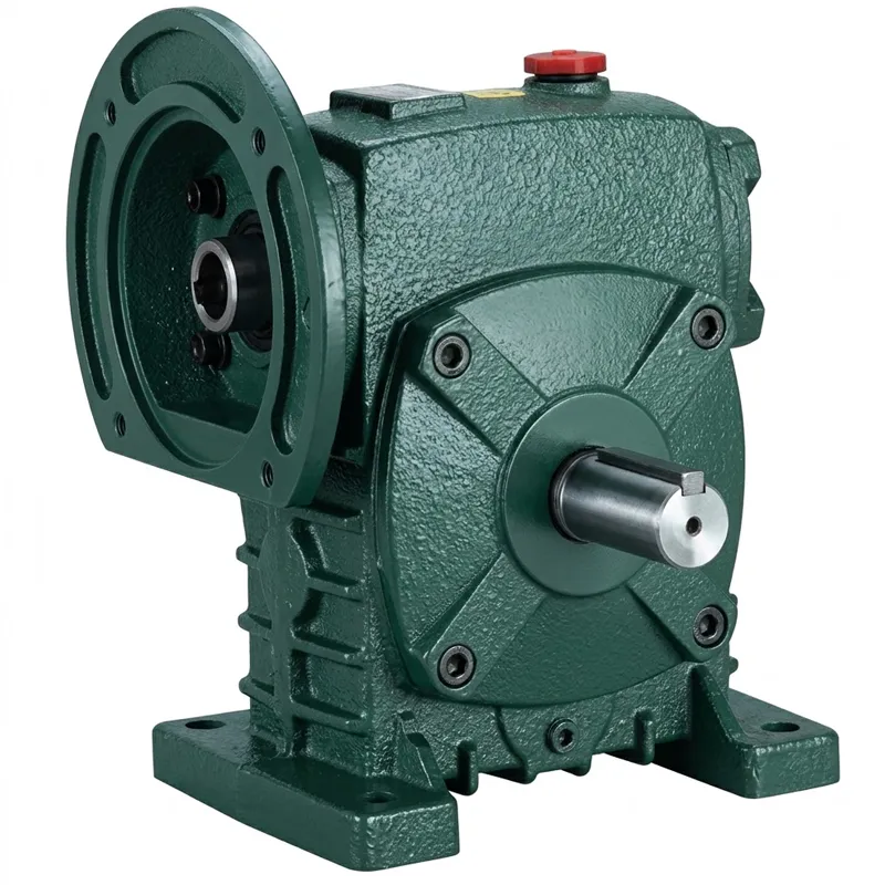
EP-WPDS 0.12 முதல் 15 kW வரையிலான உள்ளீட்டு சக்தி ஒற்றை வேகக் குறைப்பான்
Unlike conventional foot-mount worm reducers, the EP-WPDS integrates the motor mounting directly into the reducer housing via a precision-machined IEC-standard flange (LA × LB × LC × LE geometry), with a 4-LZ bolt pattern that locks the motor face securely to the reducer input. This arrangement eliminates the misalignment issues associated with separate motor bases and flexible couplings — the motor shaft engages the worm input bore directly, producing a rigid, compact drive unit that is quicker to install and easier to align than a traditional base-and-coupling setup.
Frame sizes run from 40 through 250 mm center distance, with each size accommodating one or more input power levels reflecting the torque capacity of the worm wheel at that frame. The smallest size 40 handles 0.12 kW; the largest, size 250, accommodates 11.0 kW and 15.0 kW input options. Gear ratios span 1/5 through 1/60 depending on the frame, covering the full range of output speeds useful in packaging, material handling, food processing, and general industrial automation. All six shaft direction configurations (A through F) are available, giving machine designers considerable flexibility in how the worm speed reducer output integrates with the driven equipment layout.
EP-WPDS Single Speed Reducer — 0.12 to 15 kW Input Power Range
The EP-WPDS is a motor-flanged ஒற்றை வேகக் குறைப்பான் featuring an integrated IEC flange face on the input side, allowing direct face-mount coupling to a standard electric motor without a separate adapter or coupling hub. Designed for right-angle worm gear reduction across a wide power band, the WPDS series covers input ratings from 0.12 kW through 15 kW across ten frame sizes — making it one of the most versatile motor-coupled ஒற்றை நிலை வேகக் குறைப்பான் platforms in this output class.
Technical Specifications — EP-WPDS Series
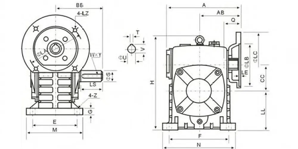
Full dimensional and performance data for the EP-WPDS ஒற்றை வேகக் குறைப்பான் series is listed below. Motor flange dimensions (LA, LB, LC, LE, LZ) follow IEC standards. Input hole dimensions (Q, U, T×V) refer to the motor-shaft bore. Output shaft dimensions (LS, S, W×Y) are the reducer output shaft parameters. All dimensions in mm; input power in kW; weight in kg. Scroll horizontally on mobile to view all columns.
| அளவு | Power (kW) | விகிதம் | ஒரு | ஏபி | பிபி | சிசி | எச் | எல்எல் | எம் | N | இ | எஃப் | ஜி | Z | லாஸ் ஏஞ்சல்ஸ் | எல்பி | எல்சி | LE | எல்இசட் | கேள்வி | யு | டி×வி | எல்.எஸ். | எஸ் | W×Y | எடை (கிலோ) | ||
|---|---|---|---|---|---|---|---|---|---|---|---|---|---|---|---|---|---|---|---|---|---|---|---|---|---|---|---|---|
| 40 | 0.12 | — | 135 | 75 | 74 | 40 | 141 | 60 | 90 | 100 | 70 | 80 | 13 | 10 | 115 | 95 | 140 | 4 | எம்.ஏ.டி. | 31 | 11 | 4×12.8 | 28 | 14 | 5×3 | 5 | ||
| 50 | 0.18 | — | 151 | 83 | 97 | 50 | 176 | 80 | 120 | 140 | 95 | 110 | 15 | 12 | 115 | 95 | 140 | 4 | எம்.ஏ.டி. | 31 | 11 | 4×12.8 | 40 | 17 | 5×3 | 8 | ||
| 60 | 0.37 | — | 167 | 91 | 112 | 60 | 202 | 90 | 130 | 150 | 105 | 120 | 20 | 12 | 130 | 110 | 160 | 4 | எம்.ஏ.டி. | 33 | 14 | 5×16.3 | 50 | 22 | 7×4 | 11 | ||
| 70 | 0.37 | 1/5 | 200 | 109 | 131 | 70 | 238 | 105 | 150 | 190 | 115 | 150 | 20 | 15 | 130 | 110 | 160 | 4 | எம்.ஏ.டி. | 40 | 14 | 5×16.3 | 60 | 28 | 7×4 | 17 | ||
| 0.75 | 165 | 130 | 200 | 4 | எம்10 | 42 | 19 | 6×21.8 | ||||||||||||||||||||
| 80 | 0.75 | 1/10 | 202 | 111 | 142 | 80 | 273 | 120 | 170 | 220 | 135 | 180 | 20 | 15 | 165 | 130 | 200 | 4.5 | எம்10 | 48 | 19 | 6×21.8 | 65 | 32 | 10×4.5 | 22 | ||
| 1.5 | 1/15 1/20 |
165 | 130 | 200 | 4.5 | எம்10 | 52 | 24 | 8×27.3 | |||||||||||||||||||
| 100 | 1.5 | 1/20 | 225 | 125 | 169 | 100 | 280 | 150 | 190 | 270 | 155 | 220 | 25 | 15 | 165 | 130 | 200 | 4.5 | எம்10 | 52 | 24 | 8×27.3 | 75 | 38 | 10×4.5 | 38 | ||
| 2.2 | 165 | 130 | 200 | 4.5 | எம்10 | 52 | 24 | 8×27.3 | ||||||||||||||||||||
| 120 | 2.2 | 1/25 1/30 |
280 | 148 | 190 | 120 | 334 | 180 | 230 | 320 | 180 | 260 | 30 | 18 | 215 | 180 | 250 | 5 | எம்12 | 63 | 28 | 8×31.3 | 85 | 45 | 12×4.5 | 64 | ||
| 3.0 | 215 | 180 | 250 | 5 | எம்12 | 63 | 28 | 8×31.3 | ||||||||||||||||||||
| 135 | 3.0 | 1/40 | 333 | 181 | 210 | 135 | 375 | 202 | 215 | 482 | 250 | 350 | 200 | 290 | 30 | 18 | 215 | 180 | 250 | 5 | எம்12 | 63 | 28 | 8×31.3 | 95 | 55 | 16×6 | 85 |
| 4.0 | 215 | 180 | 250 | 5 | எம்12 | 63 | 28 | 8×31.3 | ||||||||||||||||||||
| 155 | 5.5 | 1/50 | 375 | 202 | 252 | 155 | 448 | 247 | 235 | 541 | 275 | 390 | 220 | 320 | 35 | 21 | 265 | 230 | 300 | 5 | எம்12 | 83 | 38 | 10×41.3 | 110 | 60 | 18×7 | 118 |
| 175 | 5.5 | 1/60 | 481 | 262 | 255 | 175 | 600 | 260 | 260 | 310 | 430 | 250 | 350 | 40 | 21 | 265 | 230 | 300 | 5 | எம்12 | 83 | 38 | 10×41.3 | 110 | 65 | 18×7 | 165 | |
| 7.5 | 265 | 230 | 300 | 5 | எம்12 | 83 | 38 | 10×41.3 | ||||||||||||||||||||
| 200 | 11.0 | — | 543 | 285 | 319 | 200 | 677 | 290 | 360 | 480 | 290 | 390 | 40 | 24 | 300 | 250 | 350 | 6 | M16 | 114 | 42 | 12×45.3 | 125 | 70 | 20×7.5 | 236 | ||
| 250 | 11.0 | — | 615 | 330 | 385 | 250 | 824 | 350 | 460 | 560 | 380 | 480 | 45 | 28 | 300 | 250 | 350 | 6 | M16 | 114 | 42 | 12×45.3 | 155 | 90 | 25×9 | 396 | ||
| 15.0 | 300 | 250 | 350 | 6 | M16 | 114 | 42 | 12×45.3 |
All dimensions in mm. Input power in kW. Weight in kg. Multiple power options share housing dimensions where shown. Specifications subject to factory confirmation for non-standard configurations.
Five Key Advantages of the EP-WPDS Single Speed Reducer
① Integrated Motor Flange — No Coupling Required
The machined IEC flange input face accepts a standard motor directly, cutting installation time and eliminating the alignment procedure that external coupling setups demand. This is particularly beneficial in high-volume OEM assembly environments where building a ஒற்றை வேகக் குறைப்பான் into a machine line needs to be fast, repeatable, and free of field alignment variables.
② Six Shaft Direction Options (A–F)
With shaft direction configurations A through F — including dual-input options — the WPDS accommodates a wider range of machine layout orientations than most standard single stage right-angle worm-gear speed reducers. This eliminates the need for direction-change sprockets or additional right-angle gear pairs in complex machine frames where motor placement is constrained.
③ Wide Input Power Coverage
A single product series covering 0.12 kW through 15 kW lets procurement teams standardize on one worm gear reducer platform from small auxiliary drives through to medium-power production machinery. Multiple power options within the same frame size — for example, 0.75 kW and 1.5 kW both fitting the size 80 housing — add further flexibility for system designers working across machine variants.
④ Compact Drive Train Footprint
Eliminating the coupling and motor support base from the drive train produces a significantly shorter overall axial length compared to a conventionally mounted புழு கியர் வேகக் குறைப்பான் and separate motor assembly. This space saving is directly usable in compact machine frames — common in packaging, labeling, and conveyor equipment where machine width is constrained by production line width standards.
⑤ Direct Foot-Mount Base
Standard foot-mount base with 4-bolt Z pattern allows the WPDS to be bolted directly to a machine frame or base plate — the same mounting approach used by conventional foot-mount reducers, so existing machine structures need no modification. Combined with the flange-input motor mounting, the WPDS provides a complete speed reducer worm gearbox installation in a single bolt-up operation per side.
How the WPDS Single Speed Reducer Works
At its mechanical core, the EP-WPDS operates on the same worm-and-wheel principle shared by all right-angle single reduction worm reducers: a helically threaded worm shaft meshes with a bronze worm wheel, converting high-speed rotary input into lower-speed, higher-torque output at a 90° change of shaft direction. The ratio is determined by the number of worm wheel teeth divided by the worm's lead (number of thread starts). At 1/5, the worm has five starts and the wheel 25 teeth. At 1/60, a single-start worm drives a 60-tooth wheel — all within the same basic housing geometry.
What makes the WPDS distinct is how the input is introduced. Rather than a conventional input shaft projecting from the housing for coupling to a separately mounted motor, the WPDS presents a machined IEC flange face — the register diameter (T dimension), bolt pattern (4-LZ holes), and central bore (Q dimension) are all machined to IEC standard tolerances. The motor's own output shaft inserts through the central bore and engages the worm shaft via a precision fit, with the motor face bolted directly to the reducer flange. The result is a rigid, concentric motor-reducer assembly that needs no separate alignment procedure and maintains correct worm-shaft bearing preload because the motor weight is transferred directly into the reducer housing structure rather than hanging from a coupling.
This configuration is particularly suited to applications where a ஒற்றை வேக புழு கியர் குறைப்பான் needs to be installed and commissioned quickly — a common requirement in food and beverage plants, packaging OEM lines, and pharmaceutical processing equipment in regulated production environments across Europe, Australia, and North America.
Materials & Engineering Standards
The housing of each EP-WPDS ஒற்றை வேகக் குறைப்பான் is cast from high-grade grey iron (HT250 specification), selected for its combination of dimensional stability, vibration damping, and machinability. The motor flange register — the critical dimension that determines motor centering accuracy — is finish-machined after casting to maintain a running clearance fit tolerance that ensures motor shaft and worm input bore remain concentric within the limits required for smooth, vibration-free operation. On frame sizes from 200 upward where motor weight increases significantly, the flange bolt pattern steps up to M16 fasteners (versus M8/M10/M12 on smaller frames) to handle the elevated cantilever load from the motor mass.
The worm shaft is produced from 20CrMnTi alloy steel, carburized and case-hardened to HRC 58–62 surface hardness, with a tough ductile core retained through controlled heat treatment cycling. Ground thread flanks on the worm ensure a consistent tooth-contact pattern across the full face width of the bronze worm wheel. The worm wheel itself is centrifugal-cast from phosphor bronze (CuSn10P) — a material that provides the low sliding-friction coefficient critical in worm drives, where the tooth contact is predominantly sliding rather than rolling. This combination of a hard worm and a softer bronze wheel means the wheel acts as the planned wear component: easily inspected and replaced without affecting housing or shaft serviceability.
Input bore dimensions (Q, U, T×V in the specification table) correspond to standard IEC motor shaft diameter and keyway series, covering the range from 11 mm (M8 flange, size 40) up to 42 mm (M16 flange, size 250). This compliance with IEC motor shaft standards means the EP-WPDS accepts motors from any IEC-compliant manufacturer worldwide — a significant advantage for customers in markets where specific motor brands or local certifications are required, including CE-marked motors for European installations or CSA-approved motors for Canadian industrial projects.
பயன்பாட்டு சூழ்நிலைகள்
The direct motor-flange design of the EP-WPDS makes it a natural fit for applications where integration compactness, fast assembly, and IEC motor compatibility are all required simultaneously. The following scenarios represent the sectors where WPDS units are most commonly deployed.
Automated Packaging Lines
Filling stations, capping heads, and labeling turntables in UK and European packaging lines demand compact, easily serviced ஒற்றை வேகக் குறைப்பான் units that mount flush to the machine frame. The WPDS integrates a complete motor-reducer assembly in minimal axial space, and the standardized IEC flange allows motor replacement in the field without realigning the reducer — a key advantage in high-uptime production environments.
Food Processing Conveyors
Slat-band conveyors, spiral coolers, and product-transfer belts in Australian and Canadian food processing facilities use the WPDS for its sealed housing and straightforward maintenance profile. The direct-flange motor connection eliminates the exposed flexible coupling that can trap food debris in open conveyor environments, simplifying both cleaning and sanitation compliance.
Agricultural Machinery Auxiliaries
Seed metering drives, fertilizer spreader discs, and irrigation pivot motor drives in agricultural equipment frequently use a worm reducer motor assembly where compact size and weatherproof housing are mandatory. The WPDS sealed oil-bath construction and foot-mount base handle the vibration and environmental exposure typical of field equipment duty cycles in South American and Southeast Asian agricultural markets.
Pharmaceutical & Laboratory Equipment
Mixing vessels, reactor drives, and dispensing pumps in pharmaceutical facilities require a ஒற்றை வேக புழு கியர் குறைப்பான் that accepts precisely specified IEC motors (often with ATEX or clean-room requirements) without custom machined adapters. The WPDS flange interface accommodates these specialty motors on the same housing used for standard industrial applications — simplifying validation documentation for FDA or EMA regulated facilities.
Textile & Printing Machinery
Warp beam drives, fabric tensioning rolls, and ink metering pumps in textile and commercial printing plants across France, South Korea, and Southeast Asia rely on the low-noise worm mesh to deliver smooth, jitter-free output speed that prevents product quality issues. The WPDS motor-direct configuration also reduces the machine noise floor compared to belt-and-coupling alternatives — an important factor in multi-shift textile mill environments.
Gate, Valve & Actuator Drives
Automated gate actuators, valve stem drives, and positioning turntables use the WPDS at high ratios (1/40–1/60) where the worm drive's back-driving resistance eliminates the need for a separate position-holding brake. For municipal infrastructure and industrial plant automation projects in Brazil and the Middle East, this passive position-locking characteristic is a direct cost saving in the actuator drive system design.
எங்கள் உற்பத்தி செயல்பாடு பற்றி
With more than a decade of hands-on experience in mechanical power transmission, our engineering and production team has built substantial depth across a broad product range. We design and produce agricultural gearboxes, worm gear reducers, planetary gear drives, power take-off shafts, hydraulic cylinders, gears, chains, and motors — entirely within our own manufacturing facility, with full control over materials, machining processes, and quality verification at each stage.
Our facility holds ISO 9001:2015 certification, and production covers a comprehensive range of standard and non-standard gearboxes and assemblies in ductile iron, cast iron, cast steel, precision cast steel, and cast aluminum. We manufacture gears, sprockets, worm gears, pulleys, worms, shafts, and precision mechanical components to both catalogue specifications and custom OEM drawings. As a direct source rather than a trading intermediary, we can respond to customized single speed reducer requests — modified shaft dimensions, special coatings, altered mounting patterns — without the lead time or cost overhead of a third-party sourcing chain.
பட்டறை




தொடர்புடைய தயாரிப்புகள்
The EP-WPDS accepts standard IEC motors and fits into a broader drive system that we supply from a single source. Pairing the reducer with a matched motor or a compatible gearbox variant from our catalogue eliminates interface uncertainty and simplifies spare parts management across your machine fleet.
மின்சார மோட்டார்கள்
எங்கள் மின்சார மோட்டார்கள் are produced to IEC frame dimensions and cover the complete shaft diameter and keyway range that the WPDS input bore series accommodates — from 11 mm at size 40 through 42 mm at size 250. Specifying the motor and worm reducer motor assembly together from our facility means the register fit, keyway dimensions, and shaft length are verified against each other before shipment, eliminating the trial-and-error that can occur when sourcing reducer and motor separately.

Complete Worm Gearbox Range
The WPDS sits alongside the WPA, WPS, WPX, WPO, and NMRV series in our broader புழு கியர்பாக்ஸ் portfolio. If your application requires a different mounting configuration — standard foot-mount without flange input, hollow-shaft output, or a compact NMRV worm reducer for very tight spaces — our range provides an appropriate match. All series use the same bronze wheel and hardened worm architecture and are available as பிரீமியம் புழு குறைப்பான் variants with synthetic gear oil for extended service intervals in high-temperature or high-cycle duty applications.

அடிக்கடி கேட்கப்படும் கேள்விகள்
பதிப்பாசிரியர்: PXY