
Agriculture & Farming Equipment Application
A practical technical guide covering worm gear drive construction, ratio selection for variable field loads, material durability in outdoor agricultural environments, and maintenance considerations for PTO-driven equipment across global farming regions.
Power Take-Off (PTO) driven implements represent one of the most mechanically diverse categories of farm equipment, spanning augers, rotary mowers, grain conveyors, bale wrappers, wood chippers, irrigation pump drives, fertilizer spreaders, and dozens of other tools that derive their operating power from the tractor gearbox rather than a dedicated engine. The single speed reducer is the component that adapts the PTO output speed — standardized at 540 RPM or 1000 RPM depending on the tractor and implement specification — to whatever rotational speed the working tool actually requires. Getting this ratio right for the specific field condition and implement type is not a trivial exercise; an under-ratio selection stalls the implement under heavy crop load, while over-ratio wastes tractor fuel and reduces implement productivity unnecessarily.
In agricultural applications, the worm gear reducer must also survive working conditions that bear no resemblance to the controlled environments of factory installations. Outdoor operation exposes drive components to rain, mud, crop chaff, fertilizer dust, and wide temperature swings from freezing pre-dawn field work to mid-afternoon summer heat. Implements are frequently mounted and dismounted between field operations, subjecting mounting hardware and shaft connections to repeated engagement-disengagement cycles. In remote farming regions across sub-Saharan Africa, South Asia, South America, and Southeast Asia, the ability to maintain and repair the drive with basic tools and locally available lubricants is as important as the initial engineering specification.
This article covers the principles behind matching a single speed reducer ratio to PTO-driven implement requirements, the construction features that determine long-term field reliability, and the material properties that govern service life in agricultural outdoor environments.

PTO Speed Standards and the Role of the Single Speed Reducer
International PTO speed standards define two primary output speeds: 540 RPM (common on tractors below 50 kW in European and Asian markets, standardized under ISO 500 and ASAE S203) and 1000 RPM (standard on higher-power tractors and widely adopted in North American and Australian grain farming). Some larger tractors offer both 540 and 1000 RPM splines on the same PTO shaft, selectable by shifting an internal gearset. The implement drive designer must match the single speed reducer ratio to the PTO speed in use, and this is where field condition variables enter the calculation in ways that differ from fixed-installation industrial conveyor applications.
A grain auger, for example, may require an output shaft speed of 250–350 RPM at its flighting drive to achieve the rated grain throughput. Mounted on a 540 RPM PTO tractor, a ratio of approximately 1:1.5 to 1:2.2 suits this requirement. When the same auger model is adapted to a 1000 RPM PTO tractor — common when a farmer uses a larger tractor for field work — the single stage speed reducer ratio must be recalculated, or an alternative model with ratio steps appropriate to the 1000 RPM input must be selected. The WP series standard ratio range of 1:10 to 1:60 covers the speed reduction requirements of most PTO implement secondary drives, though the primary PTO-to-implement coupling often uses a belt drive or chain reduction ahead of the worm gear single speed reducer stage.
For implements operating under variable field load conditions — rotary mowers cutting through heavy wet grass, wood chippers encountering knots, augers moving dense compacted grain — the torque reserve of the worm gear architecture directly determines whether the implement maintains speed through the load variation or stalls. The self-locking characteristic of worm drives at ratios above approximately 1:20 also serves a safety function on implements where backdrive from the tool under its own inertia or gravity would otherwise rotate the drive train in reverse during implement disengagement.
Featured Product
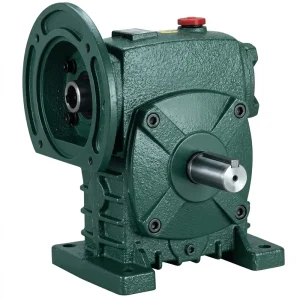
EP-WPDS Single Speed Reducer (0.12 to 15 kW Input Power)
The EP-WPDS covers an input power range from 0.12 kW to 15 kW, spanning the secondary drive requirements of implements from small irrigation pumps and fertilizer augers up to large grain handling conveyors and high-capacity rotary feed cutters. Its dual-shaft output option allows take-off on both ends of the output shaft — a configuration used in agricultural implement frames where driving two conveyor runs or two spreading discs from a single reducer simplifies the mechanical layout and reduces the number of individual drive components.
| மாதிரி | EP-WPDS |
| Input Power Range | 0.12 – 15 kW |
| Gear Stage | Single-stage worm drive |
| Ratio Range | 1:10 to 1:60 |
| Output Configuration | Dual-shaft (foot and flange mount) |
| Housing | Cast iron HT200 |
| புழு சக்கரம் | Phosphor bronze / tin-bronze alloy |
| தரநிலை | ISO 9001:2015 certified production |
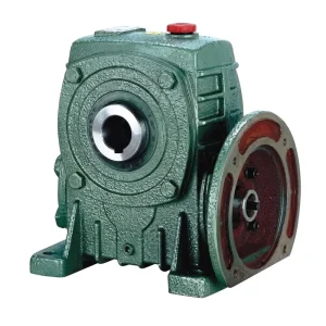
EP-WPDKA Single Speed Reducer (5–350 kg, Hollow Bore Output)
For PTO implement designs where the reducer must mount directly onto the implement drive shaft — eliminating a separate coupling and reducing overall drive train length — the EP-WPDKA hollow bore output configuration is the preferred specification. Its 5 to 350 kg load capacity range covers the full spectrum from compact seed drill drives to large hay baler conveyor drives, and the hollow bore accepts the implement shaft directly via a keyed fit to ISO 773 dimensions. In markets where implement transport on public roads requires meeting maximum width or height restrictions (such as EU Directive 2015/208 for agricultural vehicle type approval), the shorter overall drive length of the hollow bore configuration can be the deciding factor in meeting those dimensional constraints.
Manufacturing Construction: Field-Ready from the Ground Up
Agricultural implements operate in environments that are fundamentally different from the controlled factory floors for which most standard industrial reducers are designed. Rain, field mud, crop residue dust, UV exposure, freeze-thaw cycles, and the mechanical shocks of rough-terrain operation all accumulate stress on drive components over a working season. The WP series single speed reducer construction addresses these conditions through a combination of material choices and dimensional standards that have proven robust across decades of agricultural drive applications in markets ranging from North American grain belt farming to smallholder implement use in South and Southeast Asia.
20CrMnTi alloy steel, carburized and case-hardened to 58–62 HRC, ground to DIN profile tolerance. The case-hardened surface resists the impact loads that occur when an implement encounters a sudden obstruction — a stone in the path of a rotary mower, a dense mat of tangled crop residue entering an auger — without cracking or surface fatigue that would accelerate thread wear.
Centrifugally cast phosphor bronze or tin-bronze. In agricultural reducers that may go several seasons without an oil change in remote farming regions, the progressive wear characteristic of bronze provides a warning signal — through increasing noise level and vibration — before the wear reaches a failure-inducing stage. This is preferable to the sudden tooth fracture failure mode of steel-on-steel gear pairs under lubrication-starved conditions.
Gray cast iron HT200, with ribbed walls for structural rigidity during transport shock and vibration. The material has good machinability for field-repair bore work and is compatible with standard welding procedures if a mounting bracket modification is needed in the field — a consideration relevant for smaller farming operations in Africa and Asia that fabricate their own implement frames.
Double-lip rotary seals in NBR or FKM. In agricultural applications, the primary seal threat is dust and chaff ingress rather than chemical exposure. Double-lip seal geometry provides a labyrinthine path for particulate ingress that single-lip designs cannot match, keeping abrasive field material out of the gear cavity where it would accelerate bronze wheel wear.
Tapered roller bearings on the worm shaft; deep groove ball or taper bearings on the output shaft. Bearing selection is matched to the combined radial belt tension and axial thrust loads that agricultural implement drive positions impose — particularly important on auger and conveyor drives where the combined load vector changes direction as implement orientation shifts during field use.
WP series mounting configurations include foot-mounted (WPA/WPZ), flange-mounted (WPKA/WPKS), dual-output (WPDS), and hollow-bore output (WPDKA) variants — covering the range of mounting requirements in agricultural implement frames from standard base-plate mounting to direct shaft mounting without additional hardware, a significant advantage in space-constrained implement designs.

Material System: Durability Across Variable Outdoor Conditions
Material performance in agricultural drive applications is evaluated differently from food-grade or pharmaceutical settings where contamination is the primary concern. In farming equipment, the governing failure modes are mechanical fatigue from shock loading, abrasive wear from dust and chaff ingress, corrosion from rain and fertilizer exposure, and lubricant degradation from temperature cycling and extended service intervals. The WP series material system addresses each of these mechanisms specifically, without over-engineering the construction toward exotic materials that complicate procurement and field repair in agricultural contexts where supply chains can be extended and parts availability limited.
| Component | Material | Agricultural Field Relevance | Service Life Factor |
|---|---|---|---|
| Worm shaft | 20CrMnTi, carburized 58–62 HRC | Impact load resistance from sudden implement obstructions (stones, compacted material) | Hardened profile resists abrasive wear from field-dust contamination during lubrication-lean operating periods |
| Worm wheel | Phosphor / tin-bronze | Gradual wear with audible pre-failure warning — suited to seasonal maintenance schedules | Compatible with ISO VG 150–220 agricultural gear oils widely available in rural supply chains globally |
| Housing | Cast iron HT200 | Field-machinable; compatible with standard repair procedures for bracket modification or bore restoration | Paint or primer coating protects against fertilizer salt corrosion in storage between seasons |
| Shaft seals | NBR (standard) or FKM | Double-lip design excludes crop dust and chaff that would abrade bronze wheel if entering housing | NBR seal replacements available from standard bearing and seal supply outlets in most agricultural regions |
| Lubricant | ISO VG 220 gear oil | Viscosity grade maintains film thickness across 0–45°C field ambient range without seasonal grade switching | Mineral ISO VG 220 is available in agricultural supply stores across North America, Europe, Africa, and Asia |
| Output shaft | 45# steel, induction hardened | ISO 773 keyway dimensions accept standard agricultural sprockets and pulleys without custom machining | Hardened surface resists fretting corrosion at sprocket-shaft interface in seasonal mount/dismount implement cycles |
One material point specific to fertilizer spreader and crop sprayer implement drives is the corrosive effect of ammonium nitrate and urea fertilizer dust that settles on all external equipment surfaces. Cast iron housings with adequate primer or paint protection resist this form of corrosion at the surface level, but exposed bare metal at fastener threads, shaft ends, and mounting bracket contact surfaces remains vulnerable. Applying a thin layer of anti-corrosion grease to these areas at end-of-season storage is a low-cost step that significantly extends the time before corrosion reaches structurally significant depth in fastener bores or shaft bearing seats.
Matching Reducer Ratio to PTO Implement Type and Field Load
Ratio selection for a PTO-driven implement single speed reducer stage begins with the target working speed of the implement tool — the auger flighting RPM, the mower blade tip speed, the spreader disc RPM, or the conveyor belt surface speed — and works backward through the drive chain from that requirement to the available PTO input speed. Where the worm single speed gear reducer stage is one of several reduction stages in the drive chain (often preceded by a belt or chain reduction stage), only the ratio contribution of the worm stage is addressed here; the combined system ratio is the product of all individual stage ratios in series.
| PTO Implement Type | PTO Input | Typical Working Speed | WP Ratio Range | Recommended Model |
|---|---|---|---|---|
| Grain auger / conveyor | 540 RPM | 15–50 RPM (flighting) | 1:10 to 1:40 | EP-WPDS (dual shaft) |
| Hay baler conveyor drive | 540 RPM | 20–60 RPM | 1:10 to 1:30 | EP-WPDKA (hollow bore) |
| Irrigation pump drive | 540 or 1000 RPM | 100–250 RPM (pump shaft) | 1:10 to 1:15 (1000 RPM input) | WPA or WPKA |
| Bale wrapper turntable | 540 RPM | 8–20 RPM | 1:30 to 1:60 | EP-WPDKA or WPKS |
| Fertilizer spreader disc drive | 540 RPM | 50–100 RPM (slow-speed spreader) | 1:10 to 1:15 (via belt pre-reduction) | WPA or WPDS |
| Wood chipper feed drive | 540 or 1000 RPM | 10–30 RPM (feed roller) | 1:30 to 1:60 (1000 RPM input) | WPKS or WPKZ |
When field conditions vary significantly — for example, a grain auger that handles both light oat crop and dense wet maize depending on the season — the reducer should be specified based on the heaviest anticipated load condition rather than the typical operating condition. Applying a service factor of 1.5 to 2.0 to the calculated rated torque requirement accounts for start-up inertia and peak loading events, providing the torque reserve needed to maintain implement speed through the demanding portion of each operating cycle without stalling or motor overload.

Seasonal Maintenance Practices for Agricultural Single Speed Reducers
Agricultural implements typically operate for defined seasonal windows — spring seeding, summer hay operations, autumn harvest — and then sit in storage for months at a time. This storage cycle creates specific maintenance requirements for WP series single speed reducers that differ from continuous industrial applications. Neglecting these seasonal maintenance steps is the primary cause of premature reducer failure in farming equipment, more often than wear during actual operation.
Before field deployment: check oil level (fill to sight glass or level plug mark), inspect shaft seals for cracking from cold storage, verify mounting bolt torque, and engage the implement drive briefly at low PTO speed before going to full working speed to allow cold oil to distribute across all gear and bearing surfaces.
For implements running 8+ hours per day during peak harvest: check oil level and condition at least once during the peak operating period. Field dust entering past seals can contaminate oil within a season if a seal has failed. Discolored or gritty oil texture observed during mid-season check warrants immediate seal inspection and oil change before continuing.
Draining and refilling with fresh ISO VG 220 gear oil at season end removes condensate and wear particles accumulated during operation. Running the unit for 5 minutes after refill distributes fresh oil to all internal surfaces before storage, preventing corrosion of bearing raceways and shaft surfaces during the off-season period.
Clean exterior housing surfaces of crop dust, mud, and fertilizer residue before storage. Coat bare metal shaft extensions with anti-corrosion grease. Store implements in a covered area where possible; outdoor storage in freezing climates causes condensation cycling inside the housing that degrades oil and pits bearing races, even with good seals, over a long storage winter.
Complete Agricultural Drive System Components
Correct performance depends on matching the drive with the motor or PTO coupling on the input side and the implement drive hardware on the output side. The following complementary product families support complete agricultural implement drive system specification:


About the Manufacturer
The production facility behind the WP single speed reducer series holds ISO 9001:2015 certification and operates across an agricultural and industrial drive component range that includes agricultural gearboxes, worm gear reducers, planetary gear drives, power take-off shafts, hydraulic cylinders, gears, chains, and motors. This combined portfolio is particularly relevant for agricultural equipment OEMs and farm machinery builders who need multiple drivetrain components — gearboxes, PTO shafts, and hydraulic cylinder actuators — sourced from a single certified manufacturer rather than assembled from separate specialist suppliers.
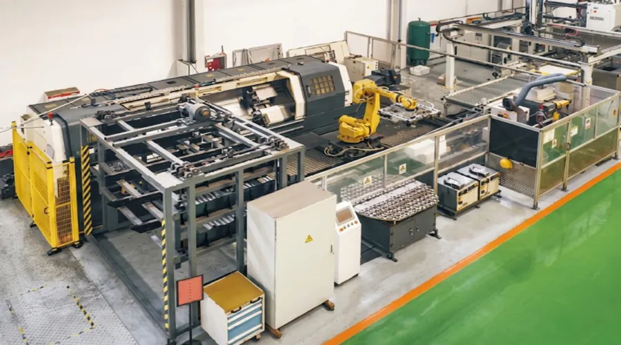
In-house manufacturing capabilities include CNC gear hobbing, precision bore machining, heat treatment, assembly, and factory test running. The material range covers ductile iron, cast iron, cast steel, precision cast steel, and cast aluminum — supporting both standard WP catalog products and non-standard assemblies for agricultural equipment builders requiring specific shaft dimensions, bore diameters, or gear ratios for implement designs outside the standard product range. Custom ratio steps and special mounting configurations can be produced to support OEM implement design requirements.
பட்டறை



அடிக்கடி கேட்கப்படும் கேள்விகள்
What single speed reducer ratio do I need for a grain auger running off a 540 RPM PTO tractor in North America? ▼
Which single stage speed reducer model is best for hay baler conveyor drives in European farm equipment designs? ▼
Where can I find a reliable single speed reducer supplier for agricultural irrigation pump drives in South and Southeast Asia? ▼
How do I get a quote for a customized single speed reducer for a non-standard PTO implement in Australia or New Zealand? ▼
What are the disadvantages of worm gear reduction gears for PTO farming equipment and when should I consider alternatives? ▼
பதிப்பாசிரியர்: PXY