
Worm Gear Manufacturer
Worm Gear · Worm Wheel ·
Worm Gear Shaft
Everything you need to understand, specify, and select the right worm drive component — product categories, technical specifications, material options, gear ratio calculation, and application guidance — in one comprehensive reference page.
What Is a Worm Drive — and Why Does It Matter?
A worm drive is a gear arrangement in which a worm screw — a shaft with a helical thread resembling a screw — meshes with a worm wheel (a toothed disc) to transmit torque between two shafts arranged at 90° to each other. This right-angle configuration, combined with the ability to achieve high reduction ratios in a single gear stage, makes the worm drive one of the most versatile and widely deployed power transmission formats in engineering history.
Three component types form the worm drive ecosystem: the Roda Gigi Cacing (the screw element, also called the worm), the Roda Cacing (the toothed driven disc), and the Worm Gear Shaft (the shaft on which the worm is formed or mounted). Each is a distinct engineering product with its own dimensional standards, material requirements, and performance parameters.
The worm drive’s defining properties — high single-stage reduction ratio, inherent self-locking at low lead angles, compact right-angle housing, and smooth sliding-contact mesh — make it the preferred drive format in elevators, conveyor reducers, steering systems, solar trackers, packaging machinery, parking systems, and precision scientific instruments worldwide.
Key Worm Drive Properties at a Glance
5:1 to 100:1+ in a single stage
90° input/output shaft arrangement
Holds position without brake at low lead angle
Smaller footprint than multi-stage parallel drives
Sliding contact produces low mesh noise
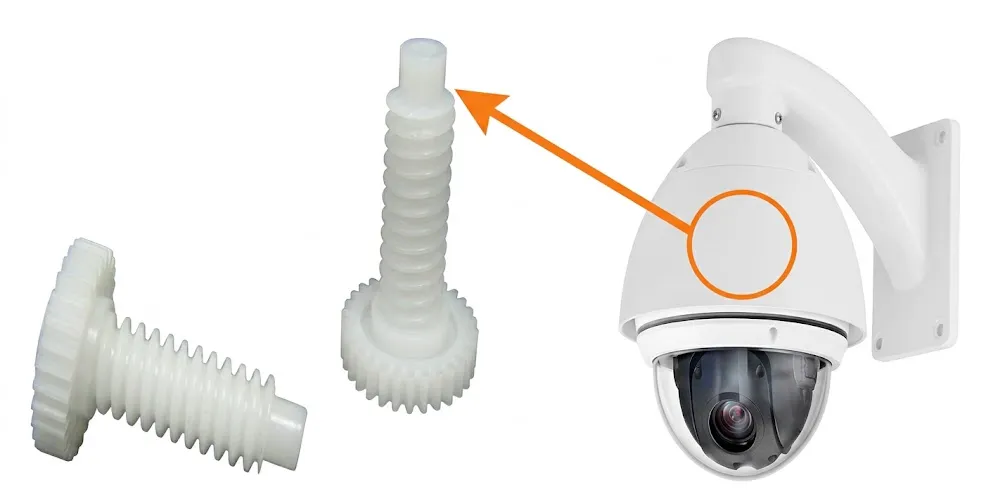
Worm Gear · Worm Wheel · Worm Gear Shaft
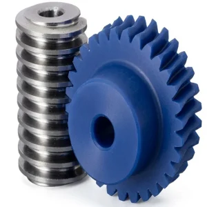
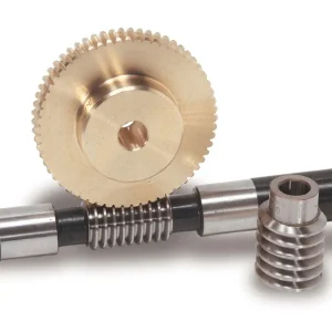
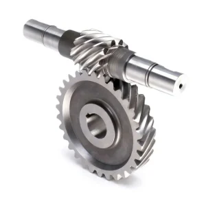
Ready to Specify Your Worm Drive Components?
Our engineering team is available to help you select the correct module, material, gear ratio, and bore configuration for your specific application. Submit a drawing, specification, or enquiry — we respond with a detailed technical quotation.
OEM / ODM
Pengiriman Global
How a Worm Drive Works — Gear Ratio, Self-Locking, and Efficiency
Understanding the core mechanics of the worm drive helps engineers specify the right component and avoid common design errors.
Gear Ratio Calculation
The worm and wheel gear ratio is calculated by a simple formula:
Examples: A 40-tooth worm wheel with a 1-start worm = 40:1. The same wheel with a 2-start worm = 20:1. A 60-tooth wheel with a 1-start worm = 60:1. Multi-start worms reduce the ratio but improve efficiency — useful when maximum reduction is not needed but better power transmission efficiency is required.
Self-Locking Explained
A worm drive is self-locking when the worm wheel cannot drive the worm shaft in reverse. This occurs when:
For typical steel-on-bronze or steel-on-brass mesh, self-locking occurs when the lead angle is below approximately 5–7°. Single-start worms at higher reduction ratios are typically self-locking. Multi-start worms at lower ratios may not be self-locking — always verify against the specific lead angle and friction coefficient when self-locking is a safety-critical requirement.
Efficiency Range
Worm drive efficiency depends primarily on the lead angle and friction coefficient:
| Perbandingan | Approx. Efficiency |
|---|---|
| 5:1 – 10:1 | 75 – 90% |
| 15:1 – 30:1 | 60 – 80% |
| 40:1 – 60:1 | 40 – 65% |
| 70:1+ | 30 – 55% |
Higher ratios = lower efficiency. Motor power must be sized to overcome friction losses, especially at high reduction ratios under sustained duty cycles.
Worm Drive Material Guide
Worm (Screw) Materials
Baja paduan yang dikeraskan permukaannya (20CrMnTi equivalent): Standard for industrial worm shafts. Case hardness 58–62 HRC, ground thread surface Ra ≤ 0.4 μm. Maximum load capacity and fatigue life.
C45 medium-carbon steel: Quenched and tempered for general industrial use. Good strength at moderate cost. Hardness 55–60 HRC after heat treatment.
Stainless steel (304 / 316 / martensitic grades): For corrosion-critical environments — food processing, pharmaceutical, marine, and chemical plant applications.
Surface Treatments
Available surface treatments for the EP worm drive series:
• Carburizing and Quenching (case depth 0.8–1.2 mm)
• High-frequency Hardening (selective tooth surface)
• Quenching and Tempering (through-hardness)
• Carbonitriding (improved wear + corrosion)
• Zinc plated / Nickel plated
• Passivation / Black Oxide
• Geomet / Dacromet (high corrosion protection)
• Powder Coating / Electrophoresis
• Anodising (aluminium components)
Worm Wheel Materials
Phosphor bronze (CuSn10P): The standard industrial worm wheel material. Excellent conformability under load, low friction against steel, and adequate strength for most industrial reducer applications.
Brass (CuZn free-cutting): Standard for precision instrument, telescope, and small mechanism drives. Best machinability at small module sizes; lubricant-free mesh.
Besi cor: Cost-effective for large, heavily loaded worm wheels in industrial gearboxes where efficiency loss and heat dissipation are managed.
POM / Nylon / PEEK: For lubricant-free light-duty drives, medical devices, and cleanroom equipment where contamination risk from lubricant is unacceptable.
Lubrication Guidance for Metal Worm Drives
Metal worm gear sets (steel worm / bronze or brass wheel) require EP (Extreme Pressure) gear oil, ISO VG 220 to VG 680 depending on operating temperature and speed. Polymer worm wheel variants (POM, nylon) operate dry — no lubricant required or recommended, as lubricant can cause polymer swelling and dimensional change. Always check the lubricant compatibility with the worm wheel material before specifying an oil type for a mixed-material drive.
Where Worm Drive Components Are Used
Industrial Machinery
Conveyor drives, mixers, agitators, rock crushers, industrial reducers
Transportation
Steering gear, window regulators, seat adjusters, HVAC flap drives,High-speed rail actuators, aviation landing gear, platform doors.
Elevators & Hoists
Lift mechanisms, chain hoists, jacking systems, stage lifts
Solar Trackers
Single-axis & dual-axis azimuth and elevation drives
Robotics
Robot joint drives, collaborative arm wrists, AGV wheel drives
Medical Devices
Infusion pumps, surgical tools, imaging positioners, lab stages
Packaging
Filling heads, capping machines, labellers, conveyors
Precision Instruments
Telescope mounts, spectrometers, CMMs, lab automation
How to Select the Right Worm Drive Component
Follow this structured selection process to specify the correct worm gear, worm wheel, and worm gear shaft for your application.
Define Required Gear Ratio
Calculate your required output speed from the motor input speed. Use the formula: Ratio = Motor RPM ÷ Required Output RPM. Round to the nearest standard tooth count (e.g., 20T, 30T, 40T, 60T worm wheel). Remember: higher ratios reduce efficiency.
Calculate Required Output Torque
Output torque = Motor torque × Ratio × Efficiency. Worm drive efficiency ranges from 40% to 90% depending on ratio and lubrication. For self-locking applications, verify the efficiency against the self-locking threshold for your specific lead angle configuration.
Select Module Size
Module determines tooth strength and physical size. Small modules (M0.5–M2) suit miniature instrument and actuator drives. Medium modules (M3–M5) cover most general industry and conveyor applications. Large modules (M8–M12) handle heavy industrial loads. Match module to the output torque and available housing size.
Choose Worm Starts
1-start worm: maximum self-locking tendency, lowest efficiency, highest ratio for a given wheel tooth count. 2-start: moderate efficiency improvement, ratio halved. 4-start: best efficiency, may not self-lock — confirm against self-locking requirement. Choose based on whether self-locking or efficiency is the priority.
Select Material
Worm: case-hardened steel (highest load capacity, longest life). Worm wheel: brass or phosphor bronze for precision and low friction, cast iron for high load, POM/nylon for lubricant-free light duty. Stainless steel variants for corrosion-critical environments. See Material section below for detailed guidance.
Specify Bore and Shaft
Worm wheel bore must match the output shaft diameter. Specify Finished bore (to exact diameter), Pilot bore (customer finishes to size), or Special bore (keyway, tapped hole, special tolerance). Worm gear shaft keyway and journal dimensions must match motor coupling and gearbox bearing layout. Provide a customer drawing for custom shaft configurations.
Quick Selection Reference
| Jenis Aplikasi | Recommended Module | Bahan Roda Cacing | Worm Starts | Penguncian Otomatis |
|---|---|---|---|---|
| Precision instrument / camera | M0.5 – M1 | Brass / POM | 1-start | Yes |
| Medical device actuator | M0.5 – M2 | POM / Brass | 1-start | Yes |
| Light industrial conveyor | M2 – M4 | Bronze / Brass | 1 or 2-start | Typically yes |
| General industrial gearbox | M3 – M8 | Phosphor bronze | 1 or 2-start | Ratio dependent |
| Solar tracker / parking system | M4 – M8 | Bronze / cast iron | 1-start | Required |
| Elevator / hoist | M5 – M12 | Phosphor bronze | 1-start | Required |
| CNC machine tool table | M3 – M8 | Bronze / duplex worm | 1-start | Yes (backlash-controlled) |
| Food / pharmaceutical line | M2 – M6 | Stainless / POM | 1 or 2-start | Application dependent |