
Construction & Material Handling · Application Guide
A technical reference for loading dock equipment engineers, material handling system designers, and maintenance teams specifying worm gear single speed reducers for dock levellers, hydraulic scissor lifts, vertical mast lifts, and work-positioning platforms across Germany, Australia, the United States, the United Kingdom, Canada, and the Netherlands.
Loading platform levellers and scissor lift mechanisms share a defining operational characteristic: they must raise and hold substantial loads — often 3,000 to 30,000 kg — with absolute position stability during the loaded period. The drive that powers the lifting mechanism must not only generate the torque required to raise the platform against gravity and load, but must also prevent back-drive — the tendency of the loaded platform to descend under gravity when the motor is de-energised. This back-drive prevention requirement is the primary reason that riduttore di velocità singolo units based on worm gear architecture are specified for these applications far more frequently than helical, bevel, or planetary reducers of equivalent power.
The self-locking property of a worm gear pair at reduction ratios above approximately 20:1 means the loaded platform is mechanically held by the gear mesh itself without requiring a holding brake — the worm wheel cannot rotate the worm backward under load because the friction angle of the worm thread is less than the lead angle. This inherent mechanical safety feature is written into the design standards for dock levellers and scissor lifts in multiple jurisdictions — including EN 1398 (dock levellers, Europe), ANSI/MH15.1 (dock levellers, North America), and AS 4216 (industrial scissor lifts, Australia) — making the riduttore a vite senza fine a functionally mandated choice in many designs rather than simply a preferred one.
Self-Locking Mechanics — Why the Worm Gear Is the Standard Choice
The self-locking condition in a worm gear pair is determined by the relationship between the worm lead angle and the friction angle of the worm-to-wheel contact. When the lead angle is less than the friction angle (typically true for reduction ratios above 20:1 in standard worm geometry), the thread cannot be driven backward by a torque applied to the worm wheel — the thread acts as a wedge that becomes more tightly engaged under back-drive force. This is quantitatively different from the holding behaviour of a helical gear pair, where back-drive is resisted only by friction at the tooth flank and in the bearings, and where a sudden shock load or vibration can overcome the frictional resistance and allow the platform to slip. A riduttore a vite senza fine a velocità singola with a 30:1 or 40:1 reduction ratio in a dock leveller or scissor lift application holds the platform position without the motor energised and without a separate mechanical brake, which simplifies the control system, reduces the number of safety-critical components requiring periodic inspection, and eliminates the brake adjustment maintenance that adds cost to a dock leveller fleet of several hundred units in a large distribution centre.
Self-locking does not eliminate the need for independent safety devices in applications where the consequences of descent are severe — EN 1398 and ANSI/MH15.1 both require a secondary anti-drop device (such as a mechanical safety leg or a hydraulic check valve) for dock levellers in addition to the primary drive self-lock. The role of the single stage speed reducer self-lock is to prevent slow controlled descent under normal load while the control system is idle, not to resist catastrophic structural failure or hydraulic line rupture. Specifying a reducer with inadequate self-lock margin — for instance a 15:1 ratio unit where a 30:1 is specified — removes the primary anti-descent function and places all reliance on the secondary safety device, which is not the design intent of the relevant standards.

Manufacturing Structure for Load-Holding Lift Applications
UN single speed worm reducer for dock leveller or scissor lift service has structural requirements that differ from the standard industrial catalogue unit in two important respects. The first is the output shaft and bearing arrangement. In a scissor lift drive, the output shaft carries a sprocket, pinion, or cam that converts the reducer’s rotational output into the linear force that raises the scissor mechanism. This conversion imposes a substantial radial load on the output shaft that acts in one direction throughout the lift cycle and reverses slightly at the top and bottom of travel as the geometry changes. The bearing arrangement must be sized not just for the torque but for this radial load — output bearings in scissor lift reducers are typically tapered roller pairs rather than single-row deep-groove ball bearings, providing the combined radial and axial load capacity the geometric loading demands.
The second structural distinction is the housing stiffness under sustained load. A dock leveller or scissor lift platform held at a fixed height by the reducer’s self-lock transmits the full load torque continuously into the worm wheel and from there into the housing bore and the output bearing. Under sustained loading, a housing that deflects — even by fractions of a millimetre — can displace the worm wheel bore relative to the worm shaft, reducing the tooth contact area and increasing the contact stress on the remaining engaged portion. This progressive distortion of the load distribution accelerates tooth wear in a pattern that is diagnostic: wear concentrated at one end of the bronze tooth face rather than uniformly distributed indicates housing deflection under sustained load. The ribbed ductile iron housing construction of the WP-series reducers is designed with sufficient wall section modulus to limit this deflection to within the gear-design assumptions for the rated load.
Material System for Dock Leveller and Scissor Lift Duty
Case-carburised to HRC 58–62 with both drive and coast flanks precision-ground to Ra 0.4–0.6 µm. The coast flank finish quality is particularly important in a scissor lift application: each time the platform descends under motor control (reverse operation), the coast flank carries the load. If the coast flank has a rougher finish than the drive flank — as in many standard catalogue reducers where only the drive flank is ground — the descent operation generates more heat and wear than the ascent, producing asymmetric tooth wear that shortens the worm wheel service life relative to the design prediction.
High-tin phosphor bronze (10% Sn, 1% Pb), centrifugally cast to minimise porosity and then finish-hobbed as a composite assembly with the ductile iron hub. The lead content provides emergency dry-running tolerance — essential in a dock leveller application where the reducer may occasionally be operated before the oil has reached operating temperature on a cold winter morning at a loading bay in Canada or Germany, creating a brief period of borderline lubrication at the worm mesh during the warm-up phase.
Ductile iron provides the fracture toughness needed to survive the impact loads that occasionally enter dock leveller drive trains when a forklift truck drives onto the leveller at speed — a common event in high-throughput distribution centres. Grey cast iron of equivalent section modulus is significantly more brittle under impact and has failed catastrophically in documented dock leveller incidents, leading the German DGUV (Deutsche Gesetzliche Unfallversicherung) technical guidelines for dock safety to specify minimum material toughness requirements for drive housings in this application.
Paired tapered roller bearings in a fixed/float arrangement carry the combined radial and axial loads of the scissor lift or dock leveller drive geometry. The fixed end carries thrust in both directions; the float end provides radial support while accommodating thermal expansion of the output shaft during sustained loaded operation. Bearing pre-load at assembly is set by a spacer shimmed to achieve 0.01–0.03 mm axial clearance in the cold condition, which converts to controlled pre-load at operating temperature.
PTFE-faced inner lip seal retains lubricant; NBR V-ring excluder on the output shaft prevents the road grit, hydraulic fluid mist, and cleaning-chemical spray that accumulate in dock pit environments from reaching the inner seal lip. V-ring exclusion extends the inner seal service life from 2000–3000 hours (single seal in a contaminated environment) to 5000–8000 hours, avoiding the oil loss and consequent bearing failure that terminates unprotected dock leveller reducer service lives prematurely.
Dock pit environments accumulate diesel exhaust condensate, hydraulic fluid leaks, and forklift tyre rubber residue on every surface. A two-component epoxy primer (60 µm DFT) followed by a polyurethane topcoat (50 µm DFT) in a mid-grey or machinery-green colour provides adequate resistance to this combination of contaminants and to the regular pressure-wash cleaning that most dock pits undergo at shift change in UK, German, and Dutch distribution centres.
Selection Reference — Single Speed Reducers for Leveller and Lift Applications
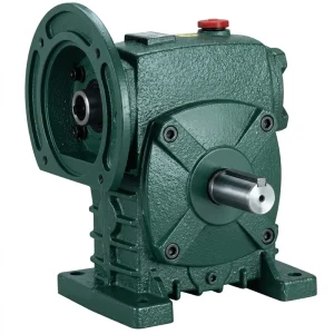
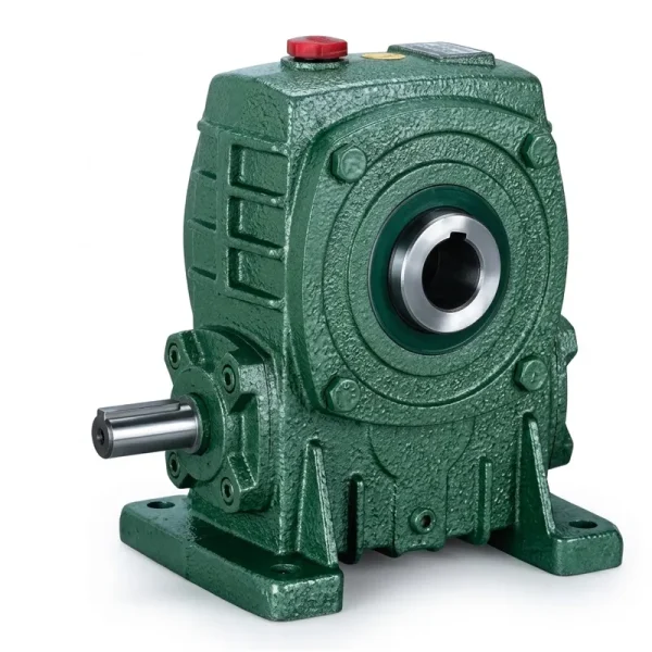
The table below covers the principal loading dock and scissor lift platform configurations where a WP-series riduttore di velocità singolo is the standard drive component. Service factor of 1.5–2.0 is applied before entering the torque table — higher end for frequent daily cycles (loading dock), lower end for infrequent maintenance lifts. The full product range is available at the riduttore di velocità singolo product page.
| Platform Type | Capacity | Motor (kW) | Rapporto | Recommended Series |
|---|---|---|---|---|
| Light dock leveller (manual lip) | 3 000 – 6 000 kg | 0.75 – 2.2 | 30:1 – 50:1 | EP-WPDS (0.12 – 15 kW) |
| Standard dock leveller (powered lip) | 6 000 – 10 000 kg | 2.2 – 5.5 | 30:1 – 50:1 | EP-WPDS / EP-WPKA (5–260 kg) |
| Industrial scissor lift (medium) | 2 000 – 8 000 kg | 2.2 – 7.5 | 25:1 – 50:1 | EP-WPKA (5–260 kg) |
| Heavy industrial scissor lift | 8 000 – 20 000 kg | 7.5 – 15 | 30:1 – 60:1 | EP-WPKS (4–365 kg) |
| Vertical mast work platform | 300 – 1 000 kg | 0.37 – 2.2 | 40:1 – 80:1 | EP-WPDS / EP-WPKZ |
Recommended Products for Leveller and Lift Applications

Environmental Conditions in Dock Pit and Lift Pit Installations
The physical environment in which a dock leveller reducer operates is one of the most corrosively challenging in the material handling sector. A loading dock pit is an open concrete box that accumulates road salt carried in on vehicle tyres (critical at North American, German, and UK docks where winter road salting is intensive), diesel exhaust particulate from trucks idling at the dock face, hydraulic fluid from truck tail-lift systems, and water from rain, snow melt, and periodic cleaning. The reducer sits at the lowest point of this pit, directly exposed to all of these contaminants through a combination of splashing, dripping, and condensation. Seal integrity is therefore the most important maintenance parameter for dock leveller reducers — an oil seal that allows lubricant to escape also allows water and salt solution to enter, converting the gear oil to an emulsion that provides negligible film thickness and accelerating worm wheel bronze corrosion.
Scissor lift pit environments are somewhat better controlled — most industrial scissor lifts operate indoors — but the drive station still accumulates hydraulic fluid from the lift cylinder circuit, metal grinding swarf in fabrication shops, and chemical cleaning agents in food processing and pharmaceutical facilities where the lifts are used to position product containers. For pharmaceutical and food facility scissor lifts in EU and Australian operations, the reducer housing coating must be chemically resistant to the quaternary ammonium sanitisers and peracetic acid concentrations used in Clean-in-Place (CIP) washdowns. Standard polyurethane topcoats are marginally resistant to these chemicals at low concentration; an epoxy novolac topcoat or a phenolic-modified epoxy provides the necessary resistance for washdown-zone installations without requiring an additional mechanical guard around the reducer.
Lubrication Selection for Low-Cycle, Load-Holding Service
Dock levellers and scissor lifts share a lubrication challenge that differs from continuous-duty conveyor and mixer drives: the duty cycle is highly intermittent — a dock leveller may cycle 50–150 times per day, each cycle lasting 15–30 seconds, with long idle periods between. During the idle period, the oil film on the worm thread flanks drains back to the sump under gravity, leaving the upper portions of the worm thread partially unlubricated. On the subsequent cold start, the first few tooth engagements occur in a mixed-lubrication regime until the oil is redistributed by the pump-like action of the rotating worm. This repeated cold-start mixed-lubrication event is why the worm wheel bronze alloy must include lead for dry-running tolerance, and why the oil specification for dock leveller drives should include a tackifier additive that increases the adhesion of the oil to the worm thread surface and reduces drain-back during idle periods.
The recommended lubricant is an ISO VG 460 gear oil with extreme-pressure additives, confirmed tin-bronze compatibility, and a tackifier that produces a pour-point-adjusted film thickness on the thread surface after 4 hours of static drain-back. For dock leveller drives at facilities in northern Canada, Norway, or Scotland where the pit temperature falls below 0 °C in winter, a synthetic PAO ISO VG 220 with a pour point below –40 °C and similar film-retention characteristics provides adequate cold-start lubrication without preheating the reducer. Oil change interval for this service is 3000–5000 hours (corresponding to approximately 3–5 years at 150 cycles/day, 250 operating days/year) with an annual oil level check and visual inspection for water contamination recommended to catch any seal-failure ingress event before it causes gear damage.

Safety Standards and Compliance Requirements for Lift Drive Reducers
Loading dock levellers and industrial scissor lifts are regulated by national and international safety standards that impose specific requirements on the drive system and its components. In Europe, dock levellers must comply with EN 1398:2009 — this standard defines the anti-drop requirements, the minimum permissible deceleration rate, and the documentation requirements for the drive mechanism. EN 1398 does not prescribe worm gear specifically, but its anti-drop requirement effectively mandates either a self-locking worm gear or a motor-actuated brake as part of the primary load-holding system. The self-locking worm approach is preferred by most European dock leveller OEMs because it avoids the brake adjustment and inspection schedule required under EN 1398 maintenance provisions for brake-based systems.
In North America, ANSI/MH15.1 (Loading Dock Equipment — Safety Requirements) governs dock leveller design and specifies a maximum uncontrolled descent rate of 25 mm per minute under rated load with the drive de-energised. A single speed worm reducer at 30:1 or higher ratio comfortably meets this requirement through its self-locking geometry — controlled descent under gravity is physically impossible at these ratios under normal operating conditions. For industrial scissor lifts in Australia, AS 4216.2 (Scissor Lifts — Safety Requirements) requires that the lift retain its position under rated load for a minimum of 15 minutes after drive de-energisation, which a self-locking worm drive at 30:1+ ratio achieves without any active holding mechanism. For equipment sold into multiple markets — a common requirement for European OEMs exporting to Australia or North America — the self-locking worm gear riduttore di velocità singolo provides a single mechanical solution that satisfies the position-holding requirements of EN 1398, ANSI/MH15.1, and AS 4216.2 simultaneously.
Capacità produttiva
Our manufacturing facility brings more than ten years of engineering experience in mechanical power transmission to the dock leveller and scissor lift drive sector, producing worm gear reducers, planetary gear drives, agricultural gearboxes, power take-off shafts, hydraulic cylinders, precision gears, roller chains, and electric motors — all under ISO 9001:2015 quality management certification. Housing and structural components are produced in ductile iron, grey cast iron, cast steel, precision investment-cast steel, and aluminium alloy matched to the load, toughness, and corrosion requirements of each product. Gear teeth, worm shafts, sprockets, pulleys, and output shafts are machined to DIN and ISO standards on multi-axis CNC hobbing, grinding, and turning centres. Customers requiring a complete dock leveller or scissor lift drive assembly — reducer, motor, adapter plate, and torque arm provision — can source all elements through a single technically accountable supplier, simplifying procurement for dock equipment OEMs in Germany, the Netherlands, the United Kingdom, Australia, Canada, and the United States who supply equipment to multiple regulatory markets simultaneously.
Workshop




Compatible Drive Components
A complete dock leveller or scissor lift drive system requires a matched motor and, for larger platforms, compatible torque arm and mounting provisions. The following product lines are available from the same manufacturing source.


Domande frequenti
Redattore: PXY