
Construction & Material Handling
A technical review of the engineering principles, gear ratio selection, material requirements, and installation practices that allow single-speed worm gear reducers to sustain reliable belt conveyor head drive performance across the variable load conditions of construction site material handling, aggregate transfer, and bulk goods distribution systems worldwide.
Belt conveyors are among the most widely used continuous material handling systems in the construction and civil infrastructure sector. Sand, crushed stone, recycled concrete aggregate, premix asphalt material, and bulk cement are all moved by belt conveyor at construction project logistics sites, batch plants, and materials processing yards across every major construction market. The head drive station at the discharge end of the conveyor is the mechanical heart of the system: it houses the drive pulley, the gearbox, and the motor that collectively generate the torque needed to pull the loaded belt against the combined resistance of material weight, belt tension, and the friction in the idler roller bearings across the full conveyor length.
Within the head drive station, the single speed reducer converts the drive motor’s rated speed — typically 960 to 1,450 rpm — into the drive pulley speed that produces the belt surface speed required for the material type and conveying rate. For construction site conveyors in the 15 to 30 metre length range operating at 0.5 to 1.5 m/s belt speed, a single stage right-angle worm-gear speed reducer provides the correct combination of speed reduction, right-angle shaft geometry for compact head-station packaging, self-locking characteristic for inclined conveyors, and resistance to the variable load conditions that result from irregular feed rates into the hopper above the conveyor tail end.
Variable Load Conditions in Construction Site Belt Conveyor Drives
Unlike mining or quarrying conveyors that typically run at near-constant load for extended shifts, construction site belt conveyors experience highly variable loading patterns that directly affect the torque demand on the head drive single speed reducer. An excavator discharging spoil onto a site conveyor introduces material in bucket-sized pulses rather than a continuous stream; a wheel loader feeding a recycled aggregate conveyor at an urban demolition site generates irregular load spikes as each scoop is tipped. The result is a conveyor that oscillates between near-empty running — where the belt tension and idler friction constitute the full drive load — and full rated load, sometimes within seconds of each other.
This variable load pattern affects the single speed reducer in two specific ways. First, it creates a cyclic torque variation at the worm-wheel mesh that is more severe than the steady-state load that continuous material stream conveyors impose. The application factor used when selecting a single speed reducer for construction site conveyor service should reflect this pulsating load character — typically a factor of 1.5 to 2.0 above the calculated steady-state torque, compared to 1.25 to 1.5 for a steadily-loaded industrial conveyor. Second, the repeated start-stop cycling that construction site conveyors experience — starting fully loaded when material has accumulated on the belt during a pause, and stopping when the feed source is repositioned — generates starting torques that can be two to three times the running torque for the initial acceleration period. The single speed reducer must be capable of surviving these starting events across thousands of cycles without accumulated fatigue damage to the worm wheel bronze teeth.
In construction markets in Southeast Asia, the Middle East, and sub-Saharan Africa, where site conveyors are frequently operated by workers without engineering supervision and feed rates are uncontrolled, the realistic worst-case load condition is more severe than the design maximum feed rate would suggest. A realistic single speed reducer selection for these markets includes a service factor margin that reflects the practical operating pattern rather than the nominal design — an approach that has demonstrably reduced in-service reducer failures on project sites in Indonesia, UAE, and Nigeria where construction logistics conveyors are routinely operated at above nominal capacity.

Head Drive Station Architecture and Reducer Positioning
The head drive station of a belt conveyor assembles the drive pulley, the reducer, the motor, and the belt take-up tensioning system into a compact structural package at the elevated discharge end of the conveyor. The physical arrangement of these components determines whether the single speed reducer is mounted with a horizontal input shaft (motor above) or vertical input shaft (motor beside), and this mounting orientation directly specifies the oil fill level and the position of the drain, fill, and breather ports in the reducer housing — a detail that is frequently overlooked when replacement reducers are fitted and that, if ignored, results in incorrect oil levels that cause rapid tooth wear.
For head drive stations where space is constrained — a common condition on portable or trailer-mounted construction site conveyors used in the UK, Germany, USA, and Australia — the compact right-angle geometry of the single stage right-angle worm-gear speed reducer allows the motor to be positioned either parallel to or perpendicular to the drive pulley shaft, giving the equipment designer flexibility that helical or parallel-shaft reducers of equivalent torque capacity do not provide. This geometric flexibility is frequently the decisive factor in favour of the worm gear speed reducer in head drive station design for compact portable conveyors, even when efficiency is slightly lower than a helical alternative.
The self-locking property of the worm reducer at gear ratios above approximately 40:1 is operationally significant in inclined conveyor head drive stations, where the loaded belt above the neutral point would back-drive the system and allow material to flow backwards if the motor is de-energised without a mechanical brake. A worm speed reducer at 40:1 or above prevents this reversal passively, without any additional mechanical device, simplifying the head drive station design and eliminating a brake as a potential failure point and maintenance item. For construction site conveyors operating on earthwork grades — where the conveyor inclination changes as the site level changes — the self-locking characteristic provides a consistent passive safety function regardless of belt gradient within the conveyor’s design operating inclination range.
Manufacturing Construction
The manufacturing construction of a single speed reducer for belt conveyor head drive service must prioritise the durability characteristics that variable load operation demands — specifically, the fatigue resistance of the worm wheel bronze teeth under repeated torque cycling, and the structural rigidity of the housing under the combined drive pulley reaction loads and shock loading from irregular material feed events. These requirements shape the manufacturing decisions at every stage from blank casting through final assembly.
The worm shaft is produced from alloy steel processed through carburizing, quenching, and profile grinding to achieve HRC 58–62 at the worm thread surface. The profile grinding step is particularly relevant for variable load conveyor service because the ground tooth form establishes a precise, consistent contact pattern across the worm wheel face — ensuring that the cyclic load pulses from irregular material feed are distributed evenly across the full engagement length rather than concentrated on one end of the tooth due to manufacturing form error. A profile error that would be tolerable in steady-state constant-load service can become a fatigue crack initiation site under the repeated peak loads of variable-load construction conveyor duty.
The cast iron housing provides the vibration damping and structural rigidity needed for conveyor head drive duty, where the reducer must react not just the gear mesh forces but also the radial loads from the drive sprocket or coupling — transmitted from the drive pulley shaft through the reducer output bearing arrangement to the housing mounting feet. For reducers in the WPDS 0.12 to 15 kW input power range, the housing wall sections at the output shaft bearing bore are specifically dimensioned to resist the bending deflection under these combined loads without allowing the shaft-centre distance to change in a way that disturbs the worm-wheel tooth contact pattern during peak load events.
Material System
The material system of a single speed reducer in a belt conveyor head drive station follows the standard worm-and-wheel architecture of the WP series, but the selection of bronze grade and the surface protection on the housing exterior are influenced by the specific exposure environment of the conveyor installation.
Worm Shaft: Case-Hardened Alloy Steel
Case-hardened to HRC 58–62 after carburizing, the worm thread surface provides the contact fatigue resistance needed under the cyclic load peaks of variable-load conveyor operation. The toughness of the case-hardened core absorbs the shock loads from bulk material drop events — when a wheel loader tips a full bucket onto the conveyor — that are transmitted back through the drive pulley and output shaft into the reducer’s worm wheel and worm shaft as brief but high-amplitude torque transients. This core toughness is what prevents tooth fracture under peak loads that would be catastrophic for a fully hardened-through gear.
Standard across WPDS, WPKA, WPKS series for conveyor duty
Worm Wheel: Phosphor Bronze (CuSn10P)
Phosphor bronze provides the fatigue strength required for the variable torque cycle of construction conveyor service while maintaining the lower hardness relative to the worm that directs wear to the replaceable wheel component rather than the worm shaft. In outdoor conveyor head station environments — typical of construction site and aggregate yard installations in the UK, Germany, USA, Australia, and Southeast Asia — the phosphor bronze’s good resistance to the combination of humidity and modest chemical exposure from aggregate wash water provides longer tooth surface life than tin-bronze alternatives without the cost premium of higher-nickel bronze grades.
Applied in WPDS, WPKA, WPKS, WPDKA series for conveyor drives
Housing: Cast Iron with External Coating
Grey cast iron (HT200) provides the vibration damping and structural rigidity required for head drive station service. For outdoor installation — which covers the majority of construction site conveyor applications — the external surface protection must be selected for the site exposure: standard alkyd paint for temperate protected sites; epoxy primer plus polyurethane topcoat for coastal or tropical construction sites where high humidity and salt air accelerate surface corrosion on inadequately protected cast iron housing surfaces.
Epoxy-polyurethane system recommended for coastal and tropical installations
Gear Ratio Selection for Belt Conveyor Head Drives Under Variable Load
The gear ratio of the single speed reducer in a belt conveyor head drive is calculated from the required belt surface speed, the drive pulley diameter, and the motor rated speed. The table below provides indicative ratio and service factor ranges for the principal construction site belt conveyor duty categories. The service factor accounts for the variable load characteristic of each application type and is applied to the calculated steady-state torque when selecting the reducer frame size.
| Application | Belt Speed (m/s) | Typical Ratio Range | Service Factor (Ks) | Load Character |
|---|---|---|---|---|
| Sand / gravel aggregate transfer | 0.8 – 1.5 | 20:1 – 40:1 | 1.5 – 2.0 | Variable, pulsating |
| Excavator spoil (earthworks) | 0.5 – 1.2 | 30:1 – 60:1 | 2.0 – 2.5 | High shock, irregular |
| Recycled concrete / demolition | 0.5 – 1.0 | 30:1 – 60:1 | 2.0 – 2.5 | High shock, heavy lump |
| Asphalt premix transfer | 0.5 – 0.8 | 40:1 – 60:1 | 1.5 | Moderate, fairly steady |
| Inclined construction site conveyor | 0.5 – 1.0 | 40:1 – 60:1 | 1.75 – 2.5 | Variable + incline load |

Recommended Product for Belt Conveyor Head Drive Applications
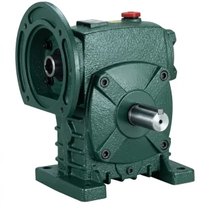
Riduttore di velocità singolo EP-WPDS con potenza in ingresso da 0,12 a 15 kW
The EP-WPDS single speed reducer covers the 0.12 to 15 kW input power range that encompasses the drive motor sizes used in the majority of construction site and material handling belt conveyor head drive stations. Its worm gear architecture delivers right-angle output geometry, self-locking at ratios above 40:1 for inclined conveyor back-drive prevention, and sealed cast iron housing construction that resists the dust, moisture, and aggregate splash typical of outdoor construction conveyor environments. Available in the standard gear ratio range from 10:1 to 60:1, with non-standard intermediate ratios available for specific belt speed requirements.
- Input power range: 0.12 to 15 kW
- Gear ratio range: 10:1 to 60:1 (single stage)
- Worm shaft: Case-hardened alloy steel, profile ground
- Worm wheel: Phosphor bronze or tin bronze
- Housing: Sealed grey cast iron, multiple mounting orientations
- Self-locking: Yes at ratios above approx. 40:1
- Non-standard ratios: Available on request
Lubrication Under Variable Load Conditions
The lubrication of a single speed reducer in a variable-load belt conveyor head drive presents a specific challenge that is different from the steady-state thermal management problem of a continuously-loaded reducer. Under steady load, the worm-wheel mesh generates heat at a rate proportional to the sustained input power and the worm gear efficiency; the housing surface dissipates this heat to the ambient air at a rate that reaches equilibrium at a stable sump temperature. Under variable load, the heat generation rate oscillates with the load — rising sharply during peak load events from bulk material drops and load pulses, then falling during the low-load intervals between feed events. The sump temperature consequently fluctuates, rather than stabilising at a single equilibrium point, and the lubricant film at the worm-wheel mesh must function across this temperature range.
ISO VG 220 or ISO VG 460 gear oil is the standard specification for construction site conveyor head drive single speed reducers, with the specific grade selected based on the gear ratio and the expected sump temperature range. For reducers in 40:1 to 60:1 ratio positions — where the low sliding velocity at the mesh limits hydrodynamic film generation and boundary lubrication conditions are more likely — ISO VG 460 with an active EP additive package provides better film stability under the load peak events than ISO VG 220. For lower ratios in the 20:1 to 30:1 range where sliding velocity is higher and film formation is more reliable, ISO VG 220 is generally adequate and has lower power loss due to churning at the higher worm shaft rotational speed.
Construction site conditions also introduce a contamination risk that lubricant management must address: airborne fine dust from stone crushing, concrete mixing, and earthwork operations deposits on the reducer housing and finds its way into the oil system through breathers and shaft seals that are not maintained in serviceable condition. Monthly checks of the shaft seal condition, the breather filter state, and the oil level — combined with an annual oil change or condition-monitoring-based change interval — provide an adequate maintenance framework for typical construction site single speed reducer service lives of 3 to 5 years between major overhauls.
Worm Gear Reducer Installation in Belt Conveyor Head Stations
The installation quality of a single speed reducer in a belt conveyor head drive station on a construction site is often compromised by the conditions under which the work is carried out — outdoor sites, time pressure, workers without specialist drive installation training, and the absence of alignment measurement tools beyond a straightedge and a spirit level. These practical constraints make it important to specify reducers that have some tolerance to minor mounting misalignment and that provide clear visual indicators of correct assembly rather than requiring precision measurement instruments for installation verification.
Shaft alignment between the reducer output shaft and the drive pulley shaft, or the intermediate chain drive sprocket, should be confirmed with a straightedge across the coupling faces or sprocket flanks before the coupling element or chain is assembled. For conveyor head drives where a chain final drive is used — common in construction site conveyors where the drive sprocket is mounted directly on the reducer output shaft and drives a sprocket on the drive pulley shaft — the chain must be aligned to within 1 mm of parallel between the sprocket faces and tensioned to the manufacturer’s specification for the chain pitch and centre distance. Insufficient chain tension causes rapid chain and sprocket wear; excessive tension overloads the reducer output shaft bearing.
The oil fill level must be confirmed after installation for the actual mounting orientation of the reducer in the head station, not assumed from the nominal design orientation. Construction site conveyors are frequently erected with slight variations in inclination from the nominal design, and a reducer whose mounting position differs from the design by as little as 5 degrees from horizontal can have its oil level shifted enough to expose the lower worm shaft bearing or to submerge the upper bearing race — both conditions that accelerate bearing wear and should be corrected by adjusting the oil fill to the correct level for the actual installed orientation.

WP Series Single Speed Reducer — Belt Conveyor Head Drive Parameters
Compatible Drive System Components
Belt conveyor head drive stations integrate the single speed reducer with an electric motor on the input and a chain, sprocket, or direct-coupled arrangement on the output side. Sourcing reducer and motor from the same supply chain provides confirmed dimensional compatibility at the input shaft interface and reduces the coupling selection effort for the OEM or site installer.
Motori elettrici
Our range of electric motors in TEFC enclosures for outdoor construction site environments covers the 0.37 to 15 kW range applicable to belt conveyor head drive stations, in both 50 Hz and 60 Hz versions for global supply. Foot-mount and flange-mount configurations suit the common motor-to-reducer coupling arrangements in conveyor head station designs.

Ingranaggio a vite senza fine
For conveyor drive positions requiring ratios above 60:1 — long inclined site conveyors with very low belt speed requirements — our cambio a vite senza fine provides two-stage compound configurations that extend the available reduction to 3,600:1, with sealed housings suitable for outdoor construction and aggregate yard environments.

Chi siamo
With over a decade of mechanical manufacturing experience, our ISO 9001:2015 certified facility produces worm gear reducers, agricultural gearboxes, planetary drive units, PTO shafts, hydraulic cylinders, precision gears, roller chains, sprockets, and motors serving industrial, construction, and agricultural customers in North America, Europe, Australia, and Asia. Standard catalogue single speed reducers and custom-engineered assemblies are produced in-house, using materials including cast iron, ductile iron, cast steel, precision investment-cast steel, and cast aluminium to match the load, weight, and environmental requirements of each application.
For belt conveyor head drive applications, our engineering team assists at the specification stage by reviewing the load spectrum, gear ratio cascade, service factor selection for the specific material type and feed pattern, and the environmental protection requirements of the installation site — whether a temperate European aggregate yard or a tropical construction site in Southeast Asia — to ensure the selected single speed reducer is correctly sized for its actual operating conditions rather than a nominal design point that may not reflect site reality.
Workshop




Domande frequenti
Which single speed reducer ratio is best for a sand and gravel belt conveyor head drive running at 1.2 m/s belt speed at an Australian aggregate yard?▼
For a sand and gravel conveyor running at 1.2 m/s belt speed driven from a 4-pole, 50 Hz motor at 1,450 rpm, the required drive pulley peripheral speed is 1.2 m/s. For a 315 mm diameter drive pulley, the required pulley speed is approximately 72 rpm, giving a required total reduction of 1,450 / 72 = 20:1. If a single speed reducer provides all the reduction at 20:1 and the reducer output shaft is directly coupled to the drive pulley, this is a straightforward single-stage selection. If an intermediate chain drive is used with a 2:1 sprocket ratio, the reducer ratio required drops to 10:1. For a variable-load aggregate yard application in Australia — where wheel loader feed rates are often uncontrolled — apply a service factor of 1.75 to the calculated steady-state torque when selecting the reducer frame size to account for the irregular load peaks.
How do I get a quote for a customised single speed reducer for a belt conveyor head drive on an inclined construction site conveyor in the UK?▼
For a quotation on a customised single speed reducer for an inclined construction site conveyor head drive in the UK, the key specification data to provide are: motor rated power (kW), motor speed (rpm), required belt surface speed (m/s), drive pulley diameter (mm), conveyor inclination angle (degrees), and the material type and maximum bulk density being conveyed. From these inputs, the supplier can calculate the required output torque and the appropriate gear ratio, confirm whether the worm gear ratio at the required value is inherently self-locking (important for inclined conveyors where back-drive prevention is a safety requirement), and identify the correct frame size after applying the appropriate service factor for the variable-load character of a construction site material handling application. Additionally, specify whether a non-standard intermediate ratio is needed for precise belt speed control or whether a standard catalogue ratio adjusted through the drive pulley diameter or sprocket ratio is acceptable.
What gear oil specification is correct for a worm gear speed reducer on a recycled demolition material belt conveyor head drive in Germany or the USA?▼
For a worm gear speed reducer on a recycled demolition material conveyor head drive — characterised by high shock loading, irregular feed rates, and typically high gear ratios in the 40:1 to 60:1 range — ISO VG 460 gear oil with an EP additive package is the standard specification in both the German DIN and USA AGMA markets. The higher viscosity maintains adequate film thickness at the worm-wheel mesh under the low sliding velocities associated with high-ratio drives, and the EP additive provides additional boundary lubrication protection during the high-torque load peaks from heavy concrete block or masonry drops onto the belt. Annual oil changes on a fixed-interval basis, or condition-monitoring-triggered changes based on oil particle analysis, are both acceptable maintenance approaches for this application type.
Where can I source a reliable single speed reducer manufacturer for belt conveyor drives at construction sites in Southeast Asia or the Middle East?▼
For single speed reducer supply to construction site belt conveyor applications in Southeast Asia or the Middle East, the practical qualification criteria for a supplier are: ISO 9001:2015 certified manufacturing; the ability to supply dimensional drawings and torque capacity data — including both mechanical torque rating and thermal rating at the actual ambient temperature at the installation site, which in the Gulf region and tropical Southeast Asia can significantly derate the nominal capacity; and availability of technical support for gear ratio selection and service factor calculation for the specific material type and feed pattern at the construction site. For markets where site maintenance is carried out by non-specialist workers, a supplier who can provide a simple installation and oil fill guide with clear diagrams and local-language instructions reduces the risk of installation errors that cause premature reducer failures in the field.
Redattore: PXY