
Construction & Material Handling
A technical overview of how single-speed worm gear reducers are specified for bridge crane long-travel and cross-travel drive systems — covering drive mechanics, gear ratio selection, load impact management, material requirements, and installation practice for industrial and construction crane applications worldwide.
Bridge cranes — also referred to as overhead travelling cranes or EOT (electric overhead travelling) cranes — form the backbone of material handling in steel fabrication shops, precast concrete manufacturing facilities, heavy equipment assembly halls, port warehouses, and industrial construction sites worldwide. Every bridge crane contains two independent travel drive systems: the long-travel (or long-stroke) drive that moves the entire bridge structure along the runway rails in the bay longitudinal direction, and the cross-travel (or lateral-stroke) drive that moves the crane trolley across the bridge girder in the transverse direction. Both drives require precise speed control, smooth starting and stopping under full rated load, and reliable brake holding when stationary on an inclined runway or in the event of power interruption.
The single speed reducer provides the fixed-ratio speed reduction between the travel motor and the drive wheel that establishes the crane’s travel speed and enables the motor to operate within its rated torque capacity during acceleration against the combined inertia and rolling resistance of the full crane structure. Understanding which single speed reducer configurations suit each travel drive position — and how the selection criteria differ between long-travel and cross-travel applications — is essential for crane OEM designers, maintenance engineers managing EOT crane fleets, and procurement teams sourcing replacement drive components for cranes in German, North American, Australian, and Southeast Asian industrial facilities.
Long-Travel Drive Architecture and Load Characteristics
The long-travel drive system of a bridge crane must accelerate and decelerate the entire mass of the bridge structure — girder, endtrucks, cross-travel trolley, and hoist — along with any suspended load. For a medium-capacity 10-tonne capacity EOT crane with a 20-metre span operating in a German steel fabrication plant or a North American automotive assembly facility, this total moving mass may reach 15 to 25 tonnes. Moving this mass at a typical long-travel speed of 20 to 50 metres per minute requires two drive units — one on each endtruck — each powered by a motor through a single speed reducer to the drive wheel or drive wheel assembly.
The load character of the long-travel drive is moderate shock — primarily from the initial start impulse when the crane begins to accelerate from rest, and from any runway irregularities that cause brief changes in rolling resistance as the drive wheels traverse joints between runway rail sections. This moderate shock character is better managed by the worm gear speed reducer’s inherent shock absorption through the bronze worm wheel tooth compliance than by rigid spur or helical gear drives that transmit shock with minimal attenuation. The worm wheel bronze acts as a partial mechanical fuse for short-duration overloads, deflecting slightly under peak torque rather than fracturing, which is why the single reduction worm reducer consistently outlasts gear reducers of equivalent rated torque in bridge crane long-travel service where electrical or mechanical faults can cause brief but severe torque spikes at the drive wheel.
Synchronisation of the two long-travel drive units — one on each endtruck — is critical for preventing crane skewing. If one drive unit delivers more torque than the other during acceleration, the bridge structure rotates about its centre, causing the leading endtruck wheel to press against the runway rail flange and generating a rail wear and structural loading problem that shortens runway life significantly. Single speed reducers with precisely matched gear ratios in both drive units, and motors with matched slip characteristics, are the mechanical basis for adequate synchronisation without active electronic control — an important consideration for crane replacement drives in markets where VFD control retrofitting is not budgeted.

Cross-Travel (Lateral-Stroke) Drive Requirements
The cross-travel drive moves the trolley — which carries the hoist and the suspended load — across the bridge girder in the lateral direction. The trolley mass is typically much lower than the full bridge mass, but the cross-travel drive must also accelerate the full rated suspended load hanging below the hoist. For a 10-tonne capacity crane, the cross-travel drive must accelerate the trolley, the hoist unit, and up to 10 tonnes of suspended load from rest to the rated cross-travel speed of typically 10 to 20 metres per minute.
The single speed reducer gear ratio for a cross-travel drive is selected to give a cross-travel speed lower than the long-travel speed — standard practice in EOT crane design because the lateral swing of the suspended load during cross-travel acceleration is a safety concern that increases with lateral speed, and because the cross-travel span (the bridge girder length) is typically much shorter than the long-travel bay length. A typical cross-travel speed of 10 to 15 m/min from the same 4-pole induction motor requires a higher gear reduction than the long-travel drive at 40 m/min, so the cross-travel single speed reducer typically has a higher ratio in the 30:1 to 50:1 range, compared to 15:1 to 25:1 for long-travel drives of comparable motor speed.
The self-locking characteristic of the worm speed reducer at ratios above approximately 40:1 is relevant in cross-travel drives where the trolley must remain stationary on the bridge girder when the cross-travel motor is de-energised. For cross-travel drives with gear ratios below the self-locking threshold — including gear ratios where the crane brake is the primary holding device — the brake rating must account for the full suspended load moment about the trolley wheel contact points, including any incline in the bridge girder due to deflection under load. In practice, using a single speed reducer with a ratio above 40:1 in the cross-travel position eliminates the brake as the sole holding device and provides a passive secondary hold that remains effective even if the brake mechanism develops a fault.
Manufacturing Construction
The manufacturing construction of a single speed reducer for bridge crane travel drive service must address the specific loading and environmental conditions that distinguish crane service from standard industrial applications. The most distinctive operational characteristic of crane travel drives is the frequent start-stop cycling: a busy crane in a steel fabrication plant or precast concrete facility in Germany or Australia may complete 50 to 200 travel movements per shift, each involving a full acceleration from rest against the combined inertia of the bridge structure and suspended load, followed by a controlled deceleration to rest. The worm wheel bronze tooth faces experience a fatigue cycle at each start event that accumulates over the crane’s service life and determines the tooth surface life.
To manage this cyclic loading, the worm shaft is produced from case-hardened alloy steel ground to HRC 58–62 at the worm thread surface, with thread profile accuracy maintained to ISO grade 7 or better to ensure even load distribution across the full engagement length on each start-stop cycle. The worm wheel is cast from phosphor bronze (CuSn10P), chosen for its fatigue strength under cyclic bending at the tooth root and its compatibility with the EP gear oil used in crane duty reducers. For the larger frame sizes applicable to heavy-duty crane long-travel drives — the WPDKA 5–350 kg series covers the weight range relevant to 10 to 30 tonne capacity crane drives — centrifugal casting of the bronze rim produces a more uniform, lower-porosity microstructure than static casting, which is important for consistent fatigue life across a production batch of matched drive units.
The housing casting is designed with adequate wall section at the output shaft bearing bores to resist the bending deflection under the combined weight of the drive wheel assembly hanging from the reducer output shaft — a load condition that is present in cranes with pendant-hung reducer configurations where the reducer and motor are mounted on the endtruck frame and the reducer output shaft carries the drive wheel directly. Deflection of the housing under this overhung load changes the worm-wheel contact pattern in the same way as a mounting distance error, so the housing rigidity is a functional engineering requirement rather than simply a structural margin.
Material System
The material system of a single speed reducer for bridge crane travel drive service follows the standard worm-and-wheel architecture with specific attention to the fatigue life demands of cyclic start-stop crane operation and the environmental conditions of industrial crane installations.
Worm Shaft: Case-Hardened Alloy Steel
After carburizing and grinding to HRC 58–62, the worm thread surface resists the contact fatigue accumulation that results from the high cycle count of crane start-stop operation. In a busy crane facility completing 200 travel movements per shift, the worm-wheel mesh experiences 200 torque transients per shift — equivalent to several million cycles over a 5-year service interval. The carburized case provides the surface hardness required to sustain this fatigue loading, while the core toughness absorbs the shock component of each start event without tooth root fracture.
Applied across WPKA, WPKS, WPDKA series for crane travel duty
Worm Wheel: Phosphor Bronze (CuSn10P)
Centrifugally cast phosphor bronze provides the combination of adequate tensile and fatigue strength for crane travel duty loading and the lower hardness relative to the steel worm that directs the progressive wear accumulation to the replaceable wheel rather than the worm shaft. In crane service, the worm wheel is typically the service life-limiting component, and the ability to replace the wheel independently of the worm shaft — provided the shaft thread shows no significant wear — significantly reduces the overhaul cost over the crane’s operational life, particularly for the larger-frame reducers used in heavy-duty long-travel drives in European and North American industrial facilities.
Centrifugally cast for WPDKA 5–350 kg series
Housing: Grey Cast Iron, Vibration-Damped
The close-grained grey cast iron (HT200) housing provides inherent vibration damping that is genuinely relevant in crane service — the combination of runway irregularities, drive wheel bounce, and hoisting-chain snatch loads creates a complex vibration environment that a housing without damping properties would transmit directly to the gear mesh. The casting geometry incorporates stiffening ribs at the bearing boss locations to resist the bending deflection that occurs when the reducer output shaft carries significant overhung load from a pendant-hung drive wheel arrangement common in European crane designs.
Standard across all WP series crane travel reducer frames
Gear Ratio Selection for Bridge Crane Travel Drives
The single speed reducer gear ratio for each bridge crane travel drive position is calculated from the motor speed, the drive wheel diameter, and the required travel speed. The table below provides indicative ratio and application factor values for the principal EOT crane travel drive configurations used in industrial facilities globally. Application factors account for the cyclic start-stop loading characteristic of crane travel drives and must be applied to the calculated steady-state torque when selecting the reducer frame size.
| Drive Position | Travel Speed (m/min) | Typical Ratio | Applic. Factor (Ks) | Self-Locking |
|---|---|---|---|---|
| Long-travel, light duty (<5 t) | 30 – 60 | 10:1 – 20:1 | 1.5 – 2.0 | No (brake required) |
| Long-travel, medium duty (5–20 t) | 20 – 40 | 15:1 – 30:1 | 1.75 – 2.25 | Partial (brake backed up) |
| Long-travel, heavy duty (>20 t) | 15 – 30 | 20:1 – 40:1 | 2.0 – 2.5 | Yes at 40:1+ (passive hold) |
| Cross-travel (trolley), standard | 10 – 20 | 30:1 – 50:1 | 1.75 – 2.25 | Yes (self-locking at >40:1) |
| Cross-travel, high-precision | 5 – 15 | 40:1 – 60:1 | 1.5 – 2.0 | Yes |

Recommended Product for Bridge Crane Travel Drive Applications
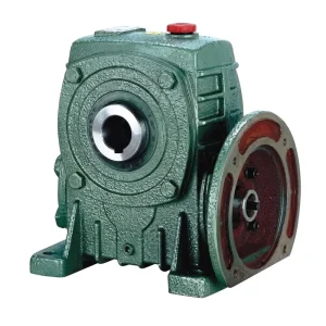
EP-WPDKA 5–350 kg Single Speed Reducer
The EP-WPDKA series spans a frame weight range of 5 to 350 kg, covering the mid-to-heavy frame sizes that correspond to the torque and structural requirements of medium and heavy-duty EOT crane long-travel and cross-travel drive systems. Its cast iron housing rigidity suits the overhung load conditions of pendant-hung crane drive configurations, and the centrifugally cast phosphor bronze worm wheel provides the fatigue life needed for the high start-stop cycle counts of busy crane facilities. Multiple mounting orientations support the varied installation geometries found in crane endtrucks and trolley frames across the range of crane designs used in industrial facilities in Europe, North America, and Asia.
- Frame weight range: 5 to 350 kg
- Gear ratio range: 10:1 to 60:1 (single stage)
- Worm shaft: Case-hardened alloy steel, profile ground to HRC 58–62
- Worm wheel: Centrifugally cast phosphor bronze
- Housing: Close-grained grey cast iron, vibration-damped
- Self-locking: Yes at ratios above approx. 40:1
- Multiple mounting orientations supported
Lubrication and Thermal Management in Crane Travel Drives
The lubrication of single speed reducers in bridge crane travel drives has a specific characteristic that distinguishes it from continuously-loaded industrial drives: the intermittent duty cycle means that the reducer alternates between short high-load operating periods — during travel and load positioning — and longer stationary periods when the crane is waiting for the next lift cycle. During the stationary period, the oil in the sump cools and partially drains from the gear surfaces; the worm-wheel mesh must therefore receive adequate lubrication immediately at restart, before the oil has warmed and redistributed.
ISO VG 220 gear oil is standard for crane travel single speed reducers in the 10:1 to 30:1 ratio range where sliding velocity is moderate and hydrodynamic film generation is reliable. For cross-travel reducers in the 40:1 to 60:1 range — where sliding velocity is lower and boundary lubrication conditions are more likely — ISO VG 460 with an EP additive package provides the necessary film quality at the low sliding speeds that occur when the worm wheel turns slowly. In cold-climate crane facilities — northern European factories in Sweden, Finland, and northern Germany where indoor temperatures in unheated or poorly-heated buildings can drop below 5°C in winter — a synthetic PAO base stock provides significantly better cold-start viscosity than mineral equivalents of the same ISO VG grade, ensuring the lubricant film reaches the worm-wheel mesh rapidly on restart rather than remaining viscous in the sump for the first minutes of operation.
Oil change intervals for crane travel single speed reducers should be based on operating cycle count rather than calendar time alone, since a crane completing 300 movements per day reaches an equivalent lubricant aging rate to a continuous-duty industrial drive operating at a much lower torque loading. Annual oil changes are a conservative baseline for typical crane facilities, with oil condition sampling at 6-month intervals providing the data to extend intervals when conditions allow or trigger early changes when oil degradation is faster than expected due to temperature extremes or water ingress from roof leaks in the crane bay.
Installation, Alignment, and Long-Travel Synchronisation
The installation of single speed reducers in bridge crane travel drive positions requires alignment accuracy to the same standards as other industrial gear drive installations — shaft parallel alignment, angular alignment within specified tolerances, and coupling assembly correct for the type used — but adds a crane-specific requirement for matched gear ratios between the two endtruck drive units to minimise crane skewing during long-travel motion.
When replacing one of two matched long-travel drive reducers, the replacement unit’s gear ratio should be confirmed by the supplier against the ratio of the unit remaining in service. Even small ratio differences — within the standard manufacturing tolerance band of a catalogue gear ratio — can produce a speed differential between the two endtruck drives sufficient to cause progressive skewing accumulation over hundreds of travel cycles, resulting in rail flange contact that wears the flange and the wheel rim and eventually requires rail and wheel replacement in addition to the original reducer replacement. Specifying matching units as a pair from a single production batch, and retaining the ratio certification documents from the original installation, provides the basis for correctly matched replacement sourcing when one unit requires replacement during the crane’s service life in a European, North American, or Australian industrial facility.

WP Series Single Speed Reducer — Bridge Crane Travel Drive Parameters
Compatible Drive System Components
Bridge crane travel drive systems integrate the single speed reducer with travel motors on the input and with drive wheels, couplings, or gear rings on the output side. Sourcing both the motor and reducer from the same supply chain confirms dimensional compatibility at the shaft interface and simplifies spare parts inventory management for crane maintenance teams managing large crane fleets in industrial facilities.
موتورهای الکتریکی
Our range of electric motors — including crane-duty TEFC induction motors rated for the frequent start-stop cycling of EOT crane travel service — covers the power range applicable to bridge crane long-travel and cross-travel drives in industrial facilities, in both 50 Hz and 60 Hz versions for global supply.

گیربکس حلزونی
For crane drive positions requiring gear ratios beyond the 60:1 single-stage limit — such as very slow cross-travel positioning drives on precision handling cranes — our worm gearbox range provides two-stage configurations that extend reduction options while maintaining the right-angle geometry and self-locking characteristics that crane travel drives require.

درباره ما
With more than ten years of mechanical engineering and manufacturing experience, our ISO 9001:2015 certified facility produces worm gear reducers, agricultural gearboxes, planetary drives, PTO shafts, hydraulic cylinders, precision gears, roller chains, sprockets, and motors for industrial, construction, and material handling customers across North America, Europe, Australia, and Asia. Standard catalogue single speed reducers and custom-engineered assemblies are produced in-house, with materials including cast iron, ductile iron, cast steel, precision investment-cast steel, and cast aluminium selected to match the structural, thermal, and environmental requirements of each application.
For bridge crane travel drive applications, our engineering team supports customers at the specification stage by reviewing the gear ratio selection for the required travel speed, confirming the application factor for the start-stop cycle frequency of the specific crane facility, assessing self-locking requirements for cross-travel and inclined long-travel positions, and advising on lubrication grade selection for the ambient temperature range at the installation site. Matched pairs for long-travel synchronisation can be produced and certified from a single production batch on request.
کارگاه



سوالات متداول
Which single speed reducer ratio is correct for the long-travel drive of a 15-tonne EOT bridge crane in a German steel fabrication plant?▼
For the long-travel drive of a 15-tonne EOT crane running at 30 m/min with a 315 mm diameter drive wheel and a 4-pole, 50 Hz motor at 1,450 rpm, the drive wheel peripheral speed at 30 m/min corresponds to a wheel speed of approximately 30 rpm. The required gear ratio is 1,450 / 30 = 48:1. This is within the standard single speed reducer ratio range and, at 48:1, also provides passive self-locking that prevents the crane from drifting when the motor is de-energised. For a German steel fabrication facility with high crane utilisation — 200+ travel movements per shift — an application factor of 2.0 should be applied to the calculated steady-state torque when selecting the reducer frame size, producing a design torque of twice the nominal running torque to account for the acceleration and deceleration cyclic loading.
Where can I source a reliable single speed gear reducer for a bridge crane cross-travel drive replacement in a UK steel processing plant?▼
For sourcing a replacement single speed gear reducer for a cross-travel drive in a UK steel processing plant, the supplier qualification criteria most relevant to this application are: ISO 9001:2015 manufacturing certification; confirmed availability of the specific gear ratio required (measured from the existing unit nameplate or calculated from the drive wheel diameter and measured trolley travel speed); dimensional drawing with toleranced shaft dimensions, keyway geometry, and housing bolt pattern for confirmation against the existing trolley frame mounting; and the ability to supply the reducer with the correct oil fill for the actual mounting orientation in the trolley. For steel processing facilities where the crane operates in proximity to hot metal or radiant heat sources, confirm with the supplier that the selected gear oil viscosity grade is appropriate for the elevated ambient temperature in the crane bay, which in some steel plant environments significantly exceeds the standard 20°C reference temperature used in reducer thermal rating data.
When should the single speed reducer be replaced on an EOT bridge crane long-travel drive at a high-utilisation precast concrete plant in Southeast Asia?▼
For a high-utilisation EOT crane at a precast concrete facility in Southeast Asia — where the crane may complete 300+ travel movements per production shift in a humid, dusty environment — planned replacement of the long-travel single speed reducer should be scheduled when oil analysis shows rising copper content from worm wheel bronze wear trending consistently above the established baseline over three or more consecutive sampling periods, or when vibration monitoring detects increased mesh frequency noise indicating tooth profile wear, or when internal inspection at an oil change reveals visible pitting across more than 4% of the active worm wheel tooth face area. Running the reducer to tooth failure in this service profile is a significantly more costly and disruptive outcome than a planned replacement during a scheduled maintenance shutdown — secondary damage to the housing bores, bearings, and worm shaft that tooth failure can cause in a high-load crane travel position typically doubles the total cost and time of the repair compared to a clean planned replacement.
تدوینگر: PXY