
FOOD & BEVERAGE INDUSTRY APPLICATION
A technical and application-focused look at worm gear speed reducer design, material systems, and operational reliability in food-grade conveyor environments worldwide.
In food processing plants, the rhythm of the conveyor line directly translates to production economics. A belt that runs too fast throws product off alignment; one that drags disrupts downstream filling, sealing, or packaging stations. Maintaining a controlled, repeatable output rate is not a preference — it is an operational prerequisite. The enkel hastighetsreducerare sits at the mechanical heart of this control challenge, converting high-speed motor rotation into the precise, stable torque that conveyor drives demand across every shift.
Across bakeries, dairy facilities, bottling lines, canning operations, and snack food plants on every continent, the worm gear speed reducer has proven to be one of the most dependable drive components available. Its architecture is straightforward: a worm shaft meshes with a worm wheel at a right angle, producing a large speed reduction in a single gear stage. This single-stage reduction eliminates the cumulative looseness and backlash that multi-stage systems can develop, keeping belt speed variation within fractions of a percent even after years of continuous duty.
This article examines why the enväxlad snäckväxelreducerare is the preferred drive solution for food industry conveyor lines — covering its mechanical construction, material selection, mounting configurations, lubrication requirements, and integration with motor systems.
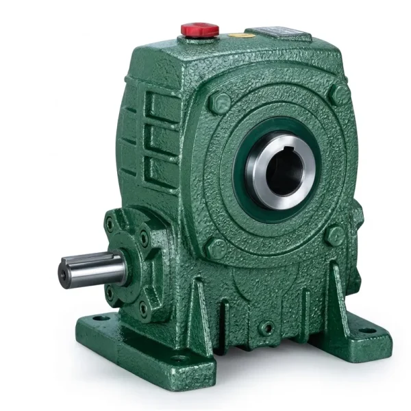
Featured Product
EP-WPKA Single Speed Reducer (5–260 kg)
The EP-WPKA is a flange-mounted, single-stage worm gear speed reducer engineered for high-rigidity mounting in conveyor and processing line applications. Its compact right-angle layout makes it ideal for installations where motor and driven shaft axes must be perpendicular — a common layout requirement in food processing conveyor frames.
| Serie | WP / WPKA |
| Load Range | 5 – 260 kg |
| Gear Stage | Single reduction (single stage) |
| Förhållandeintervall | 1/10 to 1/60 |
| Mounting Style | Flange (with foot bracket option) |
| Höljets material | Cast iron |
| Snäckhjul | Phosphor bronze / copper alloy |
| Certifiering | ISO 9001:2015 |

Manufacturing Construction of the Single Speed Reducer
The mechanical architecture of a worm gear single reduction unit is deliberately minimalist — and that simplicity is precisely what makes it so robust in food industry environments. The core assembly consists of a hardened steel worm shaft machined with precision-ground helical threads, meshing with a larger worm wheel mounted on the output shaft. Because reduction occurs in a single gear stage, there are no intermediate shafts, no planetary carrier bearings to preload, and no complex gear trains to align. Fewer moving interfaces translate directly into fewer wear points and reduced maintenance frequency.
The worm and wheel operate on a sliding contact principle rather than pure rolling contact. While this does introduce frictional losses that slightly reduce mechanical efficiency compared to helical gear sets, it also provides inherent self-locking capability at higher ratios — a safety benefit in inclined conveyor applications where backdrive must be prevented when the motor de-energizes. For horizontal food processing conveyors running at steady low speeds, the efficiency trade-off is minor relative to the operational advantages gained.
The outer housing is precision-machined from cast iron, providing dimensional stability under thermal cycling and vibration. Internal bores are finished to tight tolerances so that bearing seats, oil seals, and shaft fits all align correctly without shimming. Output shafts are ground and hardened, accepting standard coupling types, sprockets, or conveyor pulleys without the need for adapter sleeves in most configurations.
Precision-ground 20CrMnTi alloy steel, carburized and hardened to 58–62 HRC, ground to DIN/JIS profile tolerances for low-noise meshing.
Centrifugally cast phosphor bronze or tin-bronze alloy wheel body, machined to profile. Bronze provides excellent sliding wear resistance and low friction coefficient against the steel worm.
Gray cast iron (HT200 grade), pressure-tight, ribbed for structural rigidity. Machined mounting faces allow foot, flange, or combined mounting without secondary adapters.
Tapered roller bearings on the worm shaft and deep groove ball bearings or taper bearings on the output shaft, preloaded to control deflection under radial and axial loads.
Double-lip oil seals on all shaft exits, combined with labyrinth features on WPKS/WPDS variants, prevent lubricant leakage — a mandatory requirement in food-adjacent installations.
Vented pressure equalization plug prevents internal pressure buildup during thermal cycles, extending oil seal life and maintaining oil level stability during operation.
Material System: Why Each Component Material Was Chosen
Material selection in a worm speed reducer is not arbitrary. Each component serves a specific tribological or structural role, and the materials chosen for food industry variants reflect both the mechanical demands of conveyor drives and the hygiene requirements of the surrounding environment. Understanding the material system also helps maintenance teams correctly specify replacement lubricants, seals, and repair procedures.
| Component | Material | Key Property | Relevance to Food Processing |
|---|---|---|---|
| Worm shaft | 20CrMnTi alloy steel, carburized | Surface hardness 58–62 HRC | Long service life under sustained low-speed, high-torque loading typical of conveyor drives |
| Worm wheel | Tin-bronze / phosphor bronze | Low friction, wear-in capability | Absorbs minor misalignment loads without abrasive scoring; quiet operation suits noise-sensitive packing areas |
| Housing body | Cast iron HT200 | Vibration damping, dimensional stability | Resistant to deformation from frequent washdown temperature changes on production floors |
| Output shaft | 45# medium carbon steel, quenched | Torsional and bending strength | Handles shock loads from belt tension changes without fatigue cracking |
| Lubricant | ISO VG 220 gear oil (food-grade H1 optional) | Film strength, thermal stability | H1-rated synthetic food machinery lubricant (NSF/ANSI 51) available for incidental contact zones |
| Oil seals | NBR or FKM elastomer | Oil and chemical resistance | FKM seals withstand cleaning agent exposure during sanitization cycles |
The housing material choice merits particular attention in food plant environments. Cast iron provides better vibration attenuation than fabricated steel boxes, which matters in facilities where resonant vibration can cause conveyor product spillage or interference with precision weighing stations nearby. The ribbed outer geometry of the WP series housing also facilitates natural heat dissipation, keeping operating temperatures within a range that preserves lubricant viscosity and worm gear efficiency.
Explore the full range of single speed reducers suitable for food and beverage conveyor applications:

How Speed Reduction Maintains Consistent Conveyor Output Rate
The output rate of a food processing conveyor depends on two variables: belt surface speed and the regularity with which that speed is maintained. An electric motor running at 1450 RPM is not directly suitable for driving a bottle-filling conveyor that needs a surface speed of 12 m/min — the mismatch is both in speed magnitude and in torque capacity. A single stage speed reducer with a ratio of 1:20 drops motor output to 72 RPM while multiplying available torque by approximately 20 times (adjusted for mechanical efficiency, typically 70–85% for worm drive systems).
This torque multiplication is what allows the conveyor to maintain consistent speed under varying product loads. When a burst of bottles enters the conveyor from an upstream filling station, the belt momentarily sees increased resistance. A drive system without adequate torque reserve slows down, causing product pileup. The high output torque of a worm gear drive absorbs this transient loading and keeps belt velocity stable — which is why production engineers favor worm drive over direct-drive or minimal-reduction solutions for loaded food conveyors.
The self-locking characteristic of worm reducers at ratios above approximately 1:20 also benefits conveyor systems with inclined sections. On a bottle conveyor climbing to a packaging mezzanine, self-locking prevents the fully loaded belt from backsliding if power is cut without a mechanical brake. This passive safety feature reduces the need for auxiliary braking hardware, simplifying the drive train.
Mounting Configurations for Food Plant Installations
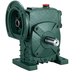
EP-WPDS (0.12 to 15 kW)
The WP series is available in five primary mounting configurations, each suited to different conveyor frame geometries and motor orientation constraints found in food processing facilities:
- WPA (foot-mounted, horizontal shaft): Standard base plate mounting. Most common on flat belt and roller conveyors where the reducer sits beneath the frame rails.
- WPDS (dual-output shaft, foot and flange): Accepts motors from 0.12 kW to 15 kW input power. Suited for driven conveyors requiring output take-off on both shaft ends, common in dual-belt transfer conveyors.
- WPKA (flange-mounted, hollow output bore): Direct shaft coupling via keyed hollow bore. Eliminates the need for a separate coupling, reducing overall drive assembly length — useful in tight conveyor frames.
- WPKS (flange-mounted, solid shaft): Higher load capacity variant of the flange series, with oversized output shaft for heavy belt tension applications such as inclined case conveyors in warehousing adjacent to food lines.
- WPZ / WPKZ (with oil port and larger sump): Extended oil capacity (0.4 to 5.2 L), designed for continuous-duty installations where oil change intervals must be extended to reduce maintenance shutdowns.
For most horizontal food processing conveyor applications, WPKA and WPA configurations cover the majority of installation requirements. The WPDS variant is particularly valued where motor flange alignment to the frame is constrained by adjacent equipment.

Selecting the Right Reduction Ratio for Your Conveyor
Ratio selection is the most consequential engineering decision when specifying a single speed gear reducer for a food conveyor. The ratio determines both the output shaft speed and the available output torque. An incorrect selection results in either a belt running too fast for filling accuracy or a motor running overloaded, shortening both motor and reducer service life. The WP single speed series covers ratios from 1:10 to 1:60 in standard steps, with extended-range variants reaching 1:110 for very low-speed applications such as aging conveyors or curing tunnel belts.
| Reduktionsförhållande | Approx. Output Speed (from 1450 RPM input) | Typical Food Line Application |
|---|---|---|
| 1:10 | 145 RPM | High-speed product transfer, can sorting |
| 1:15 | 97 RPM | Bottling line infeed conveyors |
| 1:20 | 72 RPM | General product conveying, snack food lines |
| 1:30 | 48 RPM | Dairy carton conveyors, case packing outfeed |
| 1:40 | 36 RPM | Bakery proofing line, inclined tray conveyors |
| 1:60 | 24 RPM | Curing tunnel conveyors, low-speed accumulation tables |
When selecting a ratio, design engineers should calculate required belt surface speed from throughput targets, determine the conveyor pulley circumference, and back-calculate the required output shaft speed. Adding a 15–20% service factor to the calculated torque requirement covers startup inertia and unexpected product load peaks — particularly important in food lines where surge loads from upstream equipment are common.
Lubrication Management and Maintenance Schedule
Worm gear reducers depend entirely on adequate oil film between the worm and wheel for their service life. Unlike rolling-element gears, the sliding contact mechanism has no hydrodynamic wedge to rely on at startup — the oil must be present in sufficient quantity and viscosity to coat contact surfaces from the first revolution. This is why both the initial fill level and the operating oil viscosity grade are critical parameters that maintenance teams must record and verify at commissioning.
For WP series reducers operating in food plant environments (typically 15–35°C ambient), ISO VG 220 mineral or synthetic gear oil is the standard specification. The EP-WPZ and EP-WPKZ models, with their 0.4 to 5.2-liter oil sump capacities, extend drain intervals by up to 50% compared to standard WP housing volumes when filled with synthetic ISO VG 220 oil — reducing planned stoppages on continuous production lines.
Initial Oil Fill
Fill to the center of the sight glass or oil level plug, with the reducer in its final installed orientation. Orientation affects oil level requirements — horizontal and vertical mounting use different fill points.
First Oil Change
Drain and refill after the first 300–500 operating hours. Initial running-in generates fine bronze particles from worm wheel bedding — removing this early contamination is critical to long-term gear life.
Ongoing Interval
For continuous conveyor duty (16–24 hrs/day): mineral oil at 2,000–3,000 hours; full synthetic at 4,000–6,000 hours. Adjust downward for ambient temperatures above 40°C.
Seal Inspection
Inspect shaft seals at every oil change. Evidence of oil weeping at seal lips or on mounting surfaces indicates seal replacement is needed before the next service interval.
Need a enkel hastighetsreducerare for your food processing conveyor line? Browse specifications and model comparisons in our full catalog.
WP Series Size Reference for Conveyor Drive Selection
The WP single speed reducer series is produced in 12 standard housing sizes, each defined by the center distance between the worm shaft and output shaft axes. Size selection is driven by required output torque, which in turn depends on conveyor belt load, coefficient of friction, and drive pulley diameter. The table below provides a quick-reference guide aligned to typical food processing conveyor drive requirements.
| Size (Center Distance) | Max Input Power | Output Torque Range | Conveyor Type Match |
|---|---|---|---|
| WP40 | 0.12 kW | 6 – 25 N·m | Light product: cookie/biscuit single-file belt |
| WP50 | 0.18 kW | 11 – 50 N·m | Labeling conveyor, vial infeed |
| WP60 | 0.25 kW | 18 – 90 N·m | Bottle/jar conveyor, flat table-top chain |
| WP70 | 0.37 kW | 30 – 145 N·m | Can sorting line, dairy carton conveyor |
| WP80 | 0.55 kW | 50 – 240 N·m | Case packing outfeed, heavy-duty pouch conveyor |
| WP100 | 1.1 kW | 100 – 480 N·m | Accumulation table, pallet transfer roller |
| WP120 / WP135 | 2.2 – 3.0 kW | 200 – 900 N·m | Inclined case conveyor, warehouse packing line |
| WP155 – WP250 | 5.5 – 15+ kW | 800 – 6,050 N·m | Heavy industrial food transfer, freezer conveyor |
Related Drive Components for Complete System Integration
A single speed reducer performs at its rated specifications only when paired with correctly matched drive components. The following complementary product families are available for complete conveyor drive system configuration:


Om tillverkaren
The facility behind the WP single speed reducer series holds ISO 9001:2015 certification and operates as a vertically integrated manufacturer of power transmission equipment. The production portfolio spans agricultural gearboxes, worm gear reducers, planetary gear drives, power take-off shafts, hydraulic cylinders, gears, chains, and motors — providing engineering teams and procurement departments with a consolidated source for complete drive system components.
In-house design and manufacturing capabilities extend across a broad material range: ductile iron, cast iron, cast steel, precision cast steel, and cast aluminum — enabling both standard catalog products and non-standard mechanical parts for OEM and custom conveyor system applications. Production processes include CNC gear hobbing, precision bore machining, heat treatment, assembly, and factory test running. Gears, sprockets, worm gears, pulleys, worms, and shafts are produced on the same production campus as the reducer housings, ensuring material batch consistency and dimensional traceability throughout each assembly.
Verkstad




Vanliga frågor
What is the best single speed worm gear reducer ratio for a food beverage bottling conveyor line in a North American plant? ▼
Which single stage speed reducer mounting style works best for dairy processing conveyor frames in European food facilities? ▼
How do I find a reliable single speed reducer supplier for food industry conveyor applications in Southeast Asian markets? ▼
When should I get a quote for a customized single speed reducer instead of a standard catalog unit for my conveyor project? ▼
What are the main disadvantages of reduction gears in food plant conveyor installations, and how does worm gear design address them? ▼
Redaktör: PXY