
Oil, Gas & Chemical Processing · Drive Technology
Application of Single-Speed Gear Reducers in Pipeline Pig Launchers and Valve Actuators
A technical reference covering worm gear reducer construction, material selection, torque characteristics, and product specification for oil, gas, and chemical processing installations worldwide.
Pipeline integrity and process control in oil, gas, and chemical facilities depend on drive components that perform without hesitation under demanding load profiles, exposure to aggressive media, and strict safety requirements. Two specific applications sit at the intersection of these challenges: pipeline pig launcher and receiver drive mechanisms, where a single speed reducer drives the closure door or push-plate against high line pressure; and valve actuators, where the worm gear speed reducer translates motor rotation into the precise, torque-controlled movement needed to open or close quarter-turn, multi-turn, and throttling valves across upstream, midstream, and downstream installations.
A single speed reducer in these roles is not a generic commodity. The geometry, material pairing, oil system, and shaft configuration each influence how reliably the unit performs through the temperature swings of a subsea riser or the chemical vapor exposure of a refinery valve gallery. The worm-based single stage right-angle worm-gear speed reducer is the dominant choice in both applications because it combines high reduction ratios in a compact envelope, an inherent resistance to back-driving under load, and a manufacturing tradition backed by decades of documented field performance in hydrocarbon and chemical service.
This article examines the mechanical construction and material system of the WP-series single speed gear reducer, then traces those design attributes through to specific functional requirements in pig launcher and valve actuator service. Specification tables and selection guidance are included for engineers evaluating transmission single speed reducer options for new installations or brownfield upgrades in North American, Middle Eastern, European, and Asia-Pacific process facilities.

Manufacturing Structure of the WP-Series Single Speed Reducer
The WP-series single speed reducer is built around a right-angle worm-and-wheel mesh housed in a one-piece integrally cast enclosure. The worm shaft — the high-speed input member — is positioned perpendicular to the output shaft, creating the 90-degree offset that defines the single stage right-angle worm-gear speed reducer topology. This spatial arrangement maps naturally onto valve actuator geometry, where motor and output handwheel or stem nut axes are orthogonal, and onto pig launcher drives, where space constraints on a launcher barrel saddle typically prohibit inline motor-to-gearhead arrangements.
The integral casting approach is not merely a cost decision. When the bearing bores for both worm shaft and output shaft are bored in a single fixture setup, bore-to-bore perpendicularity and concentricity are maintained to tighter tolerances than a two-piece bolted housing where parting-plane alignment introduces an additional variable. In a valve actuator that may remain stationary for months between scheduled valve operations — as is common on isolation valves in gas transmission systems — the bearing preload set at manufacture must still be correct when the drive cycles again. An integrally cast housing holds its dimensional geometry more reliably than an assembled housing whose parting-plane bolts can relax slightly over time.
The worm shaft is supported at both ends by rolling element bearings in a straddle-mounted configuration, which reduces shaft deflection under the radial and thrust loads generated during peak torque events. In a pig launcher closure mechanism where the reducer output engages a ball-screw or rack-and-pinion to seat the closure door against pipeline pressure, peak torques can briefly reach two to three times the nominal running torque. Straddle-mount bearing support prevents shaft bowing at these peaks, maintaining gear mesh geometry and avoiding the scoring risk that arises when the worm shaft deflects enough to load only part of the tooth contact width.
Material System: Housing, Worm, Wheel, and Shaft
The housing material across the WP series is grey cast iron, a choice that benefits oil and gas actuator applications in two ways beyond basic structural strength. Grey cast iron contains free graphite in a flake morphology that provides intrinsic damping of mechanical vibration — relevant for valve actuators mounted on pipelines that carry flow-induced vibration — and offers moderate corrosion resistance in atmospheres containing hydrogen sulfide at low concentrations. For applications in sour gas or high-humidity coastal environments, external epoxy powder coating over a zinc phosphate primer extends service life significantly; this surface treatment is compatible with all standard WP housing geometries.
The worm shaft is manufactured from alloy steel and case-hardened to a surface hardness typically in the range of 45–55 HRC. The hardened case is then ground to final tooth profile tolerances, removing the distortion introduced by the heat treatment cycle. Ground worm flanks present a smoother surface for tribological contact with the bronze wheel, which matters particularly at low output speeds — as found in multi-turn valve actuators — where hydrodynamic lubrication conditions are less favorable and boundary lubrication at the tooth contact must carry more of the load.
The worm wheel is produced from phosphor bronze or tin bronze. The bronze-to-hardened-steel material pairing is the defining tribological choice in worm drive engineering. Bronze has a natural affinity for lubricant films, retaining an oil layer at the mesh contact even during the slow, start-stop cycling of valve actuators that cycle only a few times per day. The bronze also acts as a sacrificial material relative to the hardened steel worm — under overload conditions, the wheel yields preferentially, protecting the more expensive worm shaft from damage and giving maintenance personnel a visible wear indicator before catastrophic failure occurs.
Output shafts and input shafts are medium-carbon or alloy steel depending on the rated torque of the frame size. Key forms and spline profiles match standard coupling bore specifications to allow integration with handwheel drives, stem nut assemblies, and motor coupling hubs without bespoke intermediate adapters. For pipeline and chemical plant installations where shaft exposure to atmospheric corrosion is an issue, stainless steel shaft extensions or sealed shaft covers can be specified at the order stage.
Featured Product: EP-WPKA Single Speed Reducer — 5 to 260 kg Shaft Load Rating
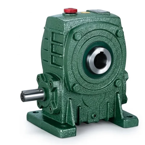
The EP-WPKA is a hollow-output-shaft single speed reducer in the WP series, where the output bore mounts directly over the driven shaft — a valve stem, ball-screw nut shaft, or handwheel stub — without requiring a separate coupling element. This shaft-mount configuration eliminates the flexural moment that a solid-shaft reducer connected via a rigid coupling would impose on the valve stem, a load component that can accelerate stem packing wear or distort soft-seat valve bodies in chemical service. The torque reaction arm that accompanies the shaft-mount arrangement provides a clean, adjustable anchor to the actuator bracket or valve body flange.
Shaft load ratings from 5 to 260 kg cover the structural weight of actuator assemblies across a wide range of valve sizes, from DN50 gate valves in chemical injection skids to DN300 ball valves on crude trunk lines. The reduction ratio range of 10:1 through 60:1 spans the torque multiplication requirements of most manual override and motorised valve actuator designs without requiring a secondary reduction stage.
| Parametro | Specifiche |
|---|---|
| Output Shaft Load Rating | 5 – 260 kg |
| Configurazione di output | Hollow bore, shaft-mount direct engagement |
| Reduction Ratios Available | 10:1 / 15:1 / 20:1 / 25:1 / 30:1 / 40:1 / 50:1 / 60:1 |
| Materiale per alloggi | Grey cast iron (epoxy coating available) |
| Worm Wheel Material | Phosphor bronze / tin bronze |
| Worm Shaft Material | Case-hardened alloy steel, ground tooth flanks |
| Mounting Style | Shaft-mount with torque arm (WPKA hollow bore) |
| Self-Locking Tendency | Ratios above ~20:1 resist back-drive under static load |
| Ambito di applicazione | Valve actuators, pipeline pig launchers, process drives |
| Center Distance Range | 40 – 250 mm (model-dependent frame sizes) |
Single Speed Reducer in Pipeline Pig Launcher and Receiver Mechanisms
A pipeline pig launcher is the pressurised vessel used to insert inspection tools, cleaning pigs, or batching spheres into a live pipeline. The closure mechanism — a quick-opening door or a threaded closure head — must be operated against the residual pressure retained in the barrel after equalisation, as well as the physical mass of a loaded pig and the friction of barrel seals. In larger-diameter launchers on crude oil, natural gas, or product pipelines, the torque required to rotate a quick-actuating closure mechanism into and out of engagement can reach several hundred Newton-metres, far beyond what manual operation can deliver safely and repeatably.
A motorised single speed reducer interposed between a geared motor and the closure mechanism provides precisely the torque multiplication and speed reduction needed. The right-angle geometry of the worm speed reducer positions the drive motor axially along the barrel, where available envelope length is generally less constrained than radial space around the barrel circumference. The single stage worm gear speed reducer’s inherent resistance to back-driving — which becomes reliable at reduction ratios above approximately 20:1 — means that once the closure is seated and the motor is de-energised, the drive train holds the closure positively without an additional brake or locking mechanism, reducing the component count on what is already a safety-critical device.
Pig receiver closure mechanisms face similar torque demands but add the complication that residual media — crude oil, condensate, pipeline chemicals — may coat the drive shaft and housing exterior during barrel opening. The single speed worm reducer’s sealed construction, combined with the cast iron housing’s resistance to incidental hydrocarbon contact, makes it suitable for this exposure. Maintenance access to the reducer in pig launcher service should be accounted for during mechanical package design: the drain plug and fill plug must be accessible when the launcher is in its normal operational position, and the drive must be disconnectable from the closure mechanism for periodic maintenance without disturbing the barrel or piping connections.

Valve Actuator Drives: Precision Torque Delivery Through a Single Reduction Worm Reducer
A valve actuator converts rotational motion from a motor or hand wheel into the torque needed to seat or unseat a valve closure element — a gate, ball, plug, butterfly disc, or globe plug. The worm gear speed reducer is the preferred transmission element in multi-turn electric actuators precisely because its geometry accommodates the wide ratio range (commonly 20:1 to 60:1) needed to bring a high-speed motor down to the 10–40 RPM output speeds at which actuator stem nuts and drive sleeves operate without imposing prohibitive radial forces on the actuator housing structure.
Quarter-turn actuator applications — ball valves, plug valves, butterfly valves — generate a distinctive torque signature. The breakaway torque required to initially unseat a wedge-seated or soft-seated valve from its closed position is typically the highest torque event in the cycle, often 1.3 to 1.8 times the running torque. The single speed worm reducer must be selected to handle this breakaway demand without overloading the worm wheel bronze, which means the rated output torque at the chosen reduction ratio must exceed the actuator’s maximum breakaway torque demand with an appropriate service factor. For gate valves in refinery service where stem thrust — rather than torque — is the limiting parameter, the output shaft load rating of the selected EP-WPKA (5 to 260 kg) covers the structural requirements of actuator top-work mounting across a wide range of valve sizes.
In chemical processing service, valve actuators may be required to operate in environments containing acidic vapors, halogen compounds, or elevated temperatures from adjacent process equipment. The grey cast iron housing provides adequate resistance to mild chemical atmospheres, but for severe service — concentrations of sulfurous gases, chlorinated solvents, or ammonia vapor — the external surface treatment should be selected with the specific chemical environment in mind. The lubricant inside the reducer also requires attention: standard mineral gear oils can deteriorate when contaminated with water condensate in humid tropical climates or cold offshore environments where the actuator housing experiences significant temperature cycling. In those cases, synthetic gear lubricants with enhanced water-shedding properties are the preferred fill.
Self-Locking Behaviour and Its Role in Oil and Gas Process Safety
The self-locking property of the worm drive is among its most operationally significant characteristics in oil and gas applications. At worm lead angles below approximately 5 to 6 degrees — which correspond to reduction ratios above roughly 20:1 — the friction at the worm-wheel tooth contact is sufficient to prevent the output shaft load from back-driving the worm. In practical terms, a valve that is driven closed by a single speed reducer remains mechanically closed when the motor is de-energised, without reliance on a separate disc brake or mechanical stop. For isolation valves on hydrocarbon pipelines, this means that a power failure during valve operation leaves the valve in its last commanded position rather than drifting open or closed under line pressure differential.
Process engineers should understand the nuance, however: self-locking is a static characteristic that can be compromised by dynamic vibration. A valve on a pulsating positive-displacement pump discharge, for example, may experience sufficient vibration to momentarily overcome the static friction at the worm mesh. In such installations, a worm drive’s self-locking tendency supplements but does not replace a proper mechanical valve locking device or solenoid-held brake where fail-safe position retention is a safety requirement. The worm drive’s resistance to back-driving is most reliably quantified by the lead angle and friction coefficient data provided in the product technical datasheet.
For pig launcher closure mechanisms specifically, the self-locking property addresses a maintenance safety concern: the drive should not allow the closure to rotate open unintentionally while personnel are in the vicinity of the barrel end. A single reduction worm reducer at 30:1 or 40:1 ratio provides a meaningful barrier against uncontrolled closure movement, complementing procedural controls and physical interlocks that are also required under industry safety management systems in upstream oil and gas operations across North America, the Middle East, and the North Sea.
WP Series Single Speed Reducer Variants: Oil and Gas Application Fit
The following table summarises WP-series configurations relevant to pig launcher and valve actuator applications, to assist specification against typical duty requirements.
| Serie | Tipo di output | Rated Shaft Load | Ratios | Best-Fit Application |
|---|---|---|---|---|
| EP-WPKA | Hollow bore, shaft-mount | 5 – 260 kg | 10:1 – 60:1 | Multi-turn valve actuator, stem-direct drive |
| EP-WPKS | Hollow bore + shrink disc | 4 – 365 kg | 10:1 – 60:1 | Pig launcher closure drive, heavy actuator top-work |
| EP-WPDKA | Hollow bore + motor flange | 5 – 350 kg | 10:1 – 60:1 | Compact motor-integrated valve actuator unit |
| EP-WPDS | Solid shaft + motor flange (top) | 0.12 – 15 kW input | 10:1 – 60:1 | Actuator bevel gear input, ancillary process drives |

Lubrication Considerations for Oil and Gas Service Environments
Worm gear drives rely on adequate oil film formation at the worm-wheel contact to separate the hardened steel worm tooth from the bronze wheel under operating load. In standard industrial environments, a VG220 or VG320 mineral gear oil meets this requirement at ambient temperatures of 5–40°C. Oil and gas installations, however, present temperature ranges well outside this band. Subsea valve actuators on deepwater tiebacks may operate at seabed temperatures of 2–4°C, where high-viscosity mineral oil reaches a pour point that impairs splash lubrication delivery. Arctic pipeline installations in northern Canada or Russia face ambient temperatures well below -20°C at the surface. In both scenarios, synthetic polyalkylene glycol (PAG) or synthetic polyalphaolefin (PAO) base oils with VG220 or VG320 equivalent viscosity at operating temperature provide the necessary film at cold conditions while maintaining adequate viscosity at higher operating temperatures.
The EP-WPZ and EP-WPKZ models carry 0.4 to 5.2 litres of gear oil depending on frame size, giving a meaningful thermal mass that buffers temperature rise during extended operation. For valve actuator applications where the reducer cycles infrequently — a weekly valve exercise rather than continuous operation — the oil temperature rarely approaches the thermal limit, and standard mineral oil with a routine annual change interval is adequate. Pig launcher closure drives that cycle repeatedly during pigging campaigns may need more frequent oil condition checks, particularly if the launcher is located in a high-ambient desert environment such as the Middle East or North Africa, where sump temperatures can reach 60–70°C during a sustained pigging operation in summer.
Water contamination of the gear oil is a recurring problem in outdoor installations subject to rain ingress or condensation cycling. A milky or cloudy oil appearance indicates water emulsification, which degrades film strength and accelerates bronze wheel wear. The WP-series housing seals are designed to resist incidental water splash, but immersion — as experienced during flooding events in low-lying process areas — requires the oil to be drained and replaced promptly after the unit is recovered. Where flooding risk is a known factor in the site design, specifying a synthetic gear oil with high water-separation (demulsibility) performance reduces the damage potential from any water ingress that does occur.
Selection Methodology for Pipeline and Valve Actuator Applications
Selecting the correct single speed reducer for oil and gas actuator service involves a defined sequence that starts at the output requirement and works back to input power. The following four steps apply to both pig launcher and valve actuator contexts.
Step 1 — Output Torque and Speed
Determine the required output torque in Newton-metres at the valve stem nut or closure mechanism, and the required output shaft speed in RPM. Both figures should include the peak demand — valve breakaway for actuators, closure seating torque for launchers — not just the running mean.
Step 2 — Reduction Ratio
Divide the motor synchronous speed by the required output speed to determine the target reduction ratio. Standard ratios of 10:1, 15:1, 20:1, 25:1, 30:1, 40:1, 50:1, and 60:1 cover the large majority of valve and launcher actuator applications without requiring a custom gear set.
Step 3 — Service Factor
Apply a service factor to the nominal output torque to arrive at the required rated output torque. Valve actuators with high breakaway demand use a service factor of 1.5–2.0; pig launcher closures with hydraulic assist at seating can use 1.25–1.5. Multiply nominal torque by the service factor and confirm the chosen reducer frame size meets this figure at the selected ratio.
Step 4 — Environment and Mounting
Confirm external surface treatment for the ambient chemical exposure (standard enamel, zinc epoxy, or heavy-duty epoxy), shaft seal specification for immersion or chemical resistance, oil grade for the temperature range, and whether a hollow-bore shaft-mount (WPKA/WPKS) or solid-shaft foot-mount configuration fits the actuator mechanical package.
For customised single speed reducer configurations — including non-standard foot-bolt patterns, special output shaft dimensions for OEM actuator bodies, or modified reduction ratios — direct inquiry with the technical team is the appropriate path. Customized single speed reducer designs are available for OEM machinery builders developing proprietary actuator products for specific pipeline or process valve applications.
Compatible Components for Complete Actuator Drive Systems
A fully engineered valve or launcher actuator drive requires matched motor and gearhead components. The following products are available from the same supply chain, enabling single-supplier sourcing that simplifies documentation, interchangeability, and warranty administration for project procurement teams.

Three-phase IEC and NEMA frame motors matched for direct coupling to WPDS and WPDKA motor-flange reducer variants. Motor and reducer sourced from one supplier guarantees shaft fit compatibility at the motor coupling interface, eliminating adapter bracket requirements that introduce additional alignment uncertainty in actuator assemblies.

Riduttore a vite senza fine a gamma completa
Where the single-stage worm drive ratio does not cover an application — for example, large isolation valves requiring output speeds below 5 RPM that need ratios exceeding 60:1 — the extended worm gearbox range includes two-stage compound and NMRV compact series options. All share the same material standards and lubrication requirements as the WP single speed series, enabling uniform maintenance practices across valve rooms and actuator packages at the same facility.
Informazioni sul produttore
The production facility behind this product line holds ISO 9001:2015 certification and maintains a broad manufacturing portfolio encompassing agricultural gearboxes, worm gear reducers, planetary gear drives, power take-off shafts, hydraulic cylinders, gears, chains, and motors. The engineering team designs and fabricates industrial and agricultural gearboxes and assemblies across a range of materials — including ductile iron, cast iron, cast steel, precision cast steel, and cast aluminum — along with gears, sprockets, worm gears, pulleys, worms, shafts, and both standard and application-specific mechanical components. OEM-customised designs and modified standard configurations are supported for machinery builders requiring specific dimensional or performance parameters outside the catalogued range.
Workshop



Domande frequenti
Redattore: PXY