
Paper, Pulp & Printing · Drive Technology
How Pulp Digesters and Chip Refiners Rely on a Single Speed Reducer for Controlled Processing Speed
A technical guide covering worm gear reducer construction, material selection, torque management, and product specification for pulp digester, chip refiner, and paper processing drive applications at mills worldwide.
Pulp and paper manufacturing is a process-intensive industry where the quality of the final sheet depends on tight control of mechanical processing conditions throughout the fibre preparation stages. In kraft and sulfite pulp mills, the digester circulation pump and blow tank agitator drives must operate at defined, stable speeds to ensure uniform cooking liquor distribution and consistent chip penetration. In mechanical and thermomechanical pulp plants, chip refiners work under enormous inter-disc pressures at controlled rotational speeds, where even a modest variation from the specified refining speed affects fibre length distribution and ultimately the strength and printability of the paper product.
Across these applications, the single speed reducer occupies the critical position between the driving motor and the processing machinery. A single stage right-angle worm-gear speed reducer achieves the required speed reduction from standard motor speeds to the operating speeds of digester agitators, refiner disc drives, and associated chip handling and screening equipment in a compact, reliable package. The worm gear’s inherent characteristics — smooth, vibration-attenuated output, high reduction in a single gear pass, and defined resistance to back-driving under load — make it well suited to the demanding mechanical environment of a pulp mill, where equipment runs continuously for weeks between planned maintenance outages.
This article covers the mechanical construction and material system of WP-series single speed reducers, their performance characteristics in digester and refiner service, selection methodology, and a product specification comparison. The content addresses the requirements of Scandinavian integrated paper mills, Canadian kraft pulp producers, Brazilian eucalyptus pulp operations, and South and Southeast Asian paper manufacturing facilities, where the drive engineering challenges differ in ambient conditions and processed fibre type but share the same fundamental need for reliable, controlled-speed mechanical drives.

Manufacturing Structure of the WP-Series Single Speed Reducer
The WP-series single speed reducer is built from a single-piece integrally cast housing that encloses both the worm shaft input and the output shaft within a right-angle arrangement. The integrity of this integral casting determines the long-term dimensional accuracy of the drive: because the bearing bores for both shaft axes are machined in a single setup, the bore-to-bore perpendicularity and concentricity reflect the machine tool accuracy rather than any assembly alignment tolerance. For pulp mill service where the reducer may operate for 8,000 hours or more per year without disassembly, this dimensional stability through extended service intervals matters considerably — bearing preload set at manufacture remains consistent, gear mesh contact geometry is maintained, and the noise and vibration signature of the drive does not deteriorate in the way that split-housing assemblies can when their parting-plane bolts relax under thermal cycling.
The worm shaft runs in rolling element bearings at both shaft ends in a straddle-mounted configuration. This arrangement distributes radial and axial loads between two bearing positions, which is important for chip refiner input drives where the refiner disc exerts significant axial thrust on the drive shaft through the disc-to-disc gap control mechanism. An overhung or cantilevered shaft arrangement would concentrate the bending moment at a single bearing, accelerating fatigue; the straddle support spreads that load and extends bearing life in proportion.
Center distances across the WP series span 40 to 250 mm in twelve standard frame sizes: 40, 50, 60, 70, 80, 100, 120, 135, 155, 175, 200, and 250 mm. Each center distance corresponds to a defined rated output torque and shaft diameter. For pulp mill applications, frame sizes from 80 mm upward are most commonly relevant, covering the torque range from small digester liquor circulation pumps at the lower end through to the chip refiner disc drive positions at the upper end of the WP series capacity range. The outer housing dimensions at each frame size also determine the mounting foot pattern and bolt circle diameter, which must match the equipment manufacturer’s drive bracket specification during mechanical package design.
Material System: Chemical and Mechanical Durability in Pulp Mill Environments
The housing is cast grey iron, a material that performs reliably in the acidic atmospheric conditions found around kraft mill digester areas, where hydrogen sulfide, sodium hydroxide aerosol, and elevated-humidity air create a mildly corrosive environment. The external surface of the housing requires appropriate protection: standard enamel paint over a phosphate primer is adequate for indoor or enclosed mill environments; two-part epoxy paint systems are specified for open or partially open installations adjacent to blow tanks, chip bins, and screening equipment where chemical splash and washdown water are routine. In Scandinavian mills, where winter ambient temperatures can drop below minus 25°C and the reducer may be installed in buildings with variable heating, the housing material’s thermal conductivity and coefficient of expansion are relatively benign factors — cast iron’s low thermal expansion coefficient means the housing geometry changes very little between cold-start and steady-state operating temperature.
The worm shaft is alloy steel, case-hardened to 45–55 HRC at the tooth flanks and precision-ground post-hardening to restore the geometric accuracy of the tooth profile that the heat treatment cycle disrupts. Ground worm flanks contact the bronze wheel with a smoother surface than a hobbed-only worm, which reduces friction heat at the mesh contact under the continuous, high-load conditions of a digester agitator or chip feed screw drive.
The worm wheel is phosphor bronze or tin bronze. The bronze-to-hardened-steel tribological pairing is the functional core of the worm drive: bronze retains lubricant film effectively at the contact zone under the sliding motion characteristic of worm mesh geometry, and yields preferentially on overload, protecting the steel worm from scoring while providing a visible, measurable wear indicator that maintenance teams can monitor by periodic backlash measurement. Input and output shafts are medium-carbon or alloy steel with keyways sized for the rated torque at each frame size. For refiner feed screw drives where the output shaft must engage a coupling hub on the screw shaft, the keyway and shaft diameter dimensions are confirmed against the machinery manufacturer’s coupling bore specification during the drive selection process.
Featured Product: EP-WPZ Single Speed Reducer — 0.4 to 5.2 L Extended Oil Capacity, Solid-Shaft Configuration
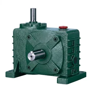
The EP-WPZ series is a solid-output-shaft foot-mount single speed reducer with an extended oil reservoir compared to the standard WP series — a sump volume ranging from 0.4 litres in the smallest frame to 5.2 litres in the largest. For pulp mill digester agitator and chip handling drives that operate continuously through production campaigns of several weeks, the larger oil volume provides a greater thermal buffer, slowing the rate of temperature rise in the sump during sustained high-load operation. The extended reservoir also dilutes the wear particle concentration produced during normal operation, reducing abrasive wear from metal fines between scheduled oil changes.
The solid output shaft with keyway provides a straightforward coupling interface to digester agitator stub shafts, chip conveyor drive couplings, and screening machine input shafts. Foot-mount installation on the drive bracket allows the motor to be positioned horizontally or in the orientation dictated by the digester structure geometry, with shaft position determined by the WPZ suffix variant (input shaft above or below, output shaft horizontal or vertical depending on model designation).
| Parametro | Specifiche |
|---|---|
| Oil Capacity Range | 0.4 – 5.2 litres (frame size dependent) |
| Configurazione di output | Solid shaft, foot-mount, extended oil reservoir |
| Reduction Ratios Available | 10:1 / 15:1 / 20:1 / 25:1 / 30:1 / 40:1 / 50:1 / 60:1 |
| Materiale per alloggi | Grey cast iron (epoxy coating for chemical exposure) |
| Worm Wheel Material | Phosphor bronze / tin bronze |
| Worm Shaft Material | Case-hardened alloy steel, ground flanks (45–55 HRC) |
| Center Distance Frame Sizes | 40 – 250 mm (12 standard sizes) |
| Gear Step | Single stage (single reduction worm gear) |
| Continuous Duty Suitability | Extended thermal reserve for long-campaign continuous operation |
| Primary Application | Digester agitator, chip conveyor, screening machine, refiner feed |
How Single Speed Reducers Control Processing Speed in Pulp Digesters
In kraft pulp cooking, the continuous digester — whether a Kamyr-type continuous digester or a batch cooking vessel — relies on a circulation system that moves white liquor and black liquor through the chip column at controlled flow rates. The circulation pumps and blow tank agitators that serve the digester circuit are typically driven by motors through worm gear speed reducers sized to deliver the required shaft speed and torque with enough stability to maintain uniform chip impregnation. The single speed reducer in this role is not a variable-speed device — the required output speed is fixed by the process design, and the reducer’s function is to maintain that speed with minimal deviation under the varying load conditions produced as chip fill level and liquor temperature change through the cooking cycle.
The worm gear reducer’s smooth power transmission is a genuine process advantage in digester service. The sliding-contact mechanism of the worm mesh does not produce the discrete tooth engagement pulses that spur or helical gear drives generate at their mesh frequency. In a blow tank agitator, for example, this smooth output reduces the oscillatory stress on the agitator shaft and impeller blades, which in turn extends the fatigue life of the agitator assembly. In Canadian kraft mills processing softwood chips — which present higher and less uniform resistance loads than hardwood chips due to chip density variation and resin content — the reducer’s load-absorbing characteristics are particularly valuable during the brief torque spikes that occur when a chip void collapses and resistance suddenly increases on the agitator blades.
Digester area installations require attention to the atmospheric conditions around the drive. The vicinity of blow valves, chip bins, and cooking liquor piping creates an environment with periodic high-humidity, chemically contaminated air that attacks unprotected metal surfaces. The single speed reducer housing surface protection specification — epoxy primer plus topcoat for open or partially open mill buildings — should be aligned with the actual chemical exposure in the installation zone, taking into account the specific pulping chemistry (kraft, sulfite, or neutral sulfite semi-chemical) and the ventilation conditions in the building.

Chip Refiner Drive Systems and the Role of the Worm Speed Reducer
Mechanical pulp production through chip refining — groundwood, thermomechanical pulp, and chemithermomechanical pulp processes — involves passing wood chips through the narrow gap between rotating refiner discs under high pressure and temperature. The refiner disc rotational speed is a primary process control variable: higher disc speed increases the specific energy input per tonne of pulp, which affects fibre length, fines content, and pulp freeness — all of which directly influence paper machine runnability and product quality. Holding disc speed within a tight tolerance band across the full load range is therefore not a mechanical convenience but a process requirement.
The main refiner disc drive on a large-scale thermomechanical pulp refiner is typically a high-power direct drive or geared drive well beyond the capacity of the WP-series single stage right-angle worm-gear speed reducer. Where the single speed gear reducer applies in chip refining is in the auxiliary drives: chip feed screw conveyors that meter chips at a controlled rate into the refiner throat, reject handling conveyor drives, screen feed drives, and latency chest agitators in the downstream pulp treatment system. In Brazilian eucalyptus pulp operations, where eucalyptus chip characteristics allow relatively fast throughput at moderate specific energy, the chip feed screw drive must track the refiner throughput precisely to prevent chip plugging or starvation of the refiner gap — both of which cause process upsets and quality deviations that are difficult to correct downstream.
For screen room and reject system drives in thermomechanical pulp plants, the single speed reducer’s self-locking characteristic at ratios above 20:1 provides an incidental process benefit: when the drive motor is stopped for a jam clearance event, the screen or agitator shaft does not rotate under the weight of retained pulp stock, which simplifies the clearance procedure and eliminates the need for a separate shaft brake on screen drives where the load is not large enough to justify a dedicated braking device.
WP Series Single Speed Reducer Variants: Pulp and Paper Application Comparison
The table below maps four WP-series configurations against the principal drive positions in pulp digesters, chip refiners, and related paper mill equipment.
| Serie | Tipo di output | Oil Capacity | Ratios | Pulp/Paper Application Fit |
|---|---|---|---|---|
| EP-WPZ | Solid shaft, foot-mount | 0.4 – 5.2 L | 10:1 – 60:1 | Digester agitator, chip conveyor, continuous long-campaign service |
| EP-WPKZ | Hollow bore, extended oil | 0.4 – 5.2 L | 10:1 – 60:1 | Screw feed direct shaft mount, screen room agitator, hot climate mills |
| EP-WPKS | Hollow bore + shrink disc | Standard sump | 10:1 – 60:1 | Reject screw drive, latency chest agitator, overload protection needed |
| EP-WPDS | Solid shaft + motor flange (top) | Standard sump | 10:1 – 60:1 | Dosing pump drive, inline motor-reducer unit on screening ancillaries |
Lubrication Management for Continuous Pulp Mill Drive Service
A pulp mill digester agitator drive that runs continuously for four to six weeks between scheduled mill shutdowns accumulates 670 to 1,000 operating hours in a single production campaign. The gear oil in the sump must maintain adequate film strength across the entire campaign without becoming so contaminated with oxidation products, wear metals, or moisture that it loses its protective function before the scheduled change interval arrives. For the EP-WPZ with its 0.4 to 5.2 litre reservoir, the larger oil volume at upper frame sizes provides the thermal mass and dilution capacity that supports extended drain intervals — the sump temperature rise is slower, and the wear metal concentration per unit volume is lower than in a small-sump unit at the same operating conditions.
Oil type selection should account for the mill’s operating environment. In Scandinavian and Finnish integrated pulp and paper mills, where winter ambient temperatures can drop below minus 20°C and drive houses may have variable heating, ISO VG220 mineral gear oil with a pour point adequate for the cold-start condition is the standard fill. For South and Southeast Asian mills in tropical climates — Indonesia, Vietnam, and Thailand are significant pulp and paper producing countries — ISO VG320 mineral or synthetic oil maintains better film thickness at the elevated sump temperatures produced by high ambient conditions. The lubricant must be confirmed as compatible with phosphor bronze worm wheel material: avoid extreme-pressure additive packages based on active sulfur, which can corrode bronze at elevated temperature.
The most reliable approach to managing oil drain intervals in continuous mill service is condition-based monitoring rather than a fixed hour count alone. A simple ferrographic analysis or visual inspection sample at the midpoint of each campaign identifies whether the oil is fit for extended service or needs early replacement. This approach avoids both unnecessary early oil changes that increase maintenance cost and extended overdue intervals that risk accelerated bronze wheel wear during the tail end of a campaign when oil condition has deteriorated.

Selection Guide for Digester and Chip Refiner Auxiliary Drives
The following four steps provide a practical selection framework for engineers specifying single speed reducers in pulp digester, chip refiner, and associated paper mill drive positions.
Step 1 — Output Speed and Torque
Define the required output shaft speed in RPM from the process design documents or the equipment manufacturer’s drive specification. Calculate or confirm the running shaft torque in Newton-metres at steady-state throughput. Apply a service factor of 1.25–1.5 for digester agitator and chip conveyor duty, increasing to 1.75–2.0 for reject screw drives where jamming events are possible.
Step 2 — Reduction Ratio
Divide motor synchronous speed by the required output speed to establish the target ratio. Standard single stage ratios from 10:1 to 60:1 cover most agitator and chip feed screw applications. Where total required reduction exceeds 60:1, a chain or belt secondary stage is added after the worm reducer output shaft to achieve the overall ratio needed.
Step 3 — Thermal Duty
Confirm that the continuous thermal power rating of the selected frame size equals or exceeds the running input power at the installation’s peak ambient temperature. For tropical South and Southeast Asian mills, apply the thermal derating factor at 40°C or above. For continuous campaign service exceeding 500 hours, specify EP-WPZ or EP-WPKZ for the extended reservoir thermal buffer.
Step 4 — Mounting and Environment
Select the output configuration — solid shaft foot-mount (WPZ) for coupled drives, hollow bore (WPKZ/WPKS) for direct shaft engagement. Specify housing surface protection based on chemical exposure in the installation zone. Confirm oil grade against ambient temperature range and confirm bronze compatibility of the lubricant additive system.
Compatible Drive Components for Pulp and Paper Mill Systems
A complete digester agitator or chip conveyor drive package requires matched motor and gearhead components. Both product lines below are available from the same supply source, enabling unified procurement that simplifies documentation, spare-parts stocking, and after-sales technical support at pulp and paper facilities managing multiple drive positions across the process line.

Three-phase IEC and NEMA frame motors in continuous-duty ratings suited for digester and chip handling drive service. Sourcing motor and single speed reducer together from the same supplier confirms that the motor shaft and flange dimensions match the WPDS or WPKZ motor-flange interface directly, eliminating coupling adapters that add mechanical interfaces and alignment requirements to drive positions that may be difficult to access for precision alignment work in the mill structure.

Riduttore a vite senza fine a gamma completa
Where larger digester agitators or high-torque blow tank drives require output torques beyond the WP single-stage range — or where the total reduction ratio needed exceeds 60:1 requiring a compound two-stage arrangement — the extended worm gearbox programme provides suitable alternatives. All carry the same phosphor bronze worm wheel, hardened steel worm, and cast iron housing material standards as the WP single speed series, enabling consistent maintenance specifications and lubricant stocking across all gearbox types at the same facility.
Informazioni sul produttore
The manufacturing facility operates under ISO 9001:2015 certification and covers a broad production scope: worm gear reducers, planetary gear drives, agricultural gearboxes, power take-off shafts, hydraulic cylinders, electric motors, gears, sprockets, and drive chains. Engineering and fabrication capabilities extend across ductile iron, cast iron, cast steel, precision cast steel, and cast aluminum housings and assemblies, with in-house production of gears, worm gears, pulleys, worms, and shafts in both standard catalogue configurations and non-standard application-specific designs. OEM development programmes for pulp and paper equipment builders, screening machine manufacturers, and chip handling system integrators are supported through direct technical collaboration with the engineering team.
Workshop




Domande frequenti
Meta Description (copy below):
— covering worm gear structure, materials, lubrication, and product selection for global paper and pulp mill installations.
Redattore: PXY