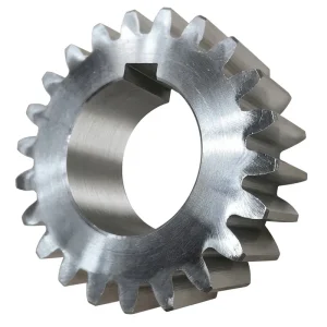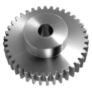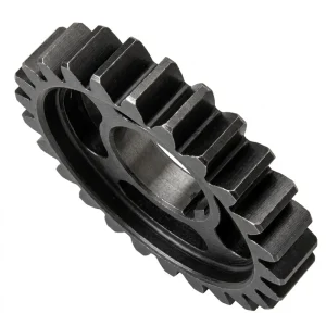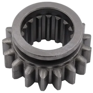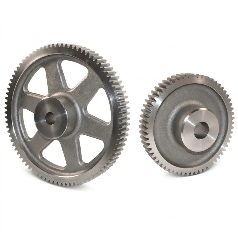
EP-European Standard Spur Gear
The EP-European Standard Spur Gear series is a comprehensive range of precision-engineered cylindrical gears manufactured from high-quality C45 steel. Designed with a standard 20° pressure angle, this series covers a wide spectrum of modules including Mod 1, 1.5, 2, 2.5, 3, 4, 5, and 6, accommodating tooth counts (Z) from 12 up to 127. The gears feature standardized dimensions for pitch diameter (d), addendum diameter (da), dedendum diameter (df), and bore diameter (d_1), ensuring compatibility with standard shafts. Two distinct tooth width options are available: Type “A” offers wider faces (e.g., 80mm for Mod 6) for heavy load capacity, while Type “B” provides compact profiles (e.g., 60mm for Mod 6) for space-constrained applications. With bore sizes ranging from 8mm to 90mm and outer diameters extending to 387mm, these C45 gears provide robust durability and precise torque transmission for diverse industrial machinery.
EP-European Standard Spur Gear — Metric Precision Parallel-Shaft Drive Gears for Industrial and Automation Applications
The EP-European Standard Spur Gear series delivers metric-dimensioned, involute tooth profile spur gears manufactured from C45 carbon steel to DIN and ISO accuracy standards. With tooth counts spanning Z=12 through Z=127, module sizes from Mod.1 to Mod.6, and a 20° pressure angle throughout, this spur gear family covers the full breadth of industrial parallel-shaft drive requirements — from compact instrument drives and conveyor head shafts to heavy gearbox output stages and large industrial machinery drives. The involute spur gear is the foundational parallel-shaft gear type used in mechanical engineering worldwide: its straight teeth run parallel to the rotational axis, delivering a mechanically efficient and straightforwardly machinable power transmission component that drives pumps, compressors, feeders, winders, positioning tables, and conveyor drives across virtually every manufacturing sector globally. This series addresses procurement requirements from industrial equipment builders in Germany, the United Kingdom, the Netherlands, Australia, Canada, South Korea, and the United States, with standardised metric dimensions that allow direct drop-in compatibility with European standard machine designs. Material is C45 carbon steel throughout the standard range, with heat treatment options available to extend surface life and load capacity across the module range.
Technical Specification — EP-European Standard Spur Gear (Selected Sizes)
The tables below present representative dimensional data for the EP-European Standard Spur Gear series. All dimensions follow DIN 867 / ISO 54 metric spur gear geometry. Diameters shown are: da = tip diameter, d = pitch diameter, df = root diameter, D = bore diameter (mm). Tooth width "B" denotes the wider tooth face option; tooth width "A" is the narrower standard option. Full dimensional tables covering Mod.1 through Mod.6 across all tooth counts from Z=12 to Z=127 are available in the complete product catalogue. Material: C45 carbon steel throughout standard range.
Tooth Width B — Module Reference (mm)
| Tooth Width B — Mod.1 / Mod.1.5 / Mod.2 / Mod.2.5 (Pressure Angle 20°, Material: C45) | ||||||||
|---|---|---|---|---|---|---|---|---|
| Z | Mod.1 da/d/df/D | Mod.1.5 da/d/df/D | Mod.2 da/d/df/D | Mod.2.5 da/d/df/D | ||||
| 12 | 14/12/9/— | 21.0/18.0/14/8 | 28/24/18/10 | 35.0/30.0/22/10 | ||||
| 15 | 17/15/12/— | 25.5/22.5/18/8 | 34/30/24/10 | 42.5/37.5/30/12 | ||||
| 20 | 22/20/17/8 | 33.0/30.0/25/10 | 44/40/34/10 | 55.0/50.0/40/12 | ||||
| 30 | 32/30/27/10 | 48.0/45.0/40/12 | 64/60/54/14 | 77.5/75.0/64/14 | ||||
| 40 | 42/40/37/12 | 63.0/60.0/54/14 | 84/80/72/14 | 105.0/100.0/88/16 | ||||
| 60 | 62/60/57/16 | 93.0/90.0/84/16 | 124/120/112/20 | 155.0/150.0/136/20 | ||||
| 80 | 82/80/77/12 | 123.0/120.0/115/16 | 164/160/152/20 | 205.0/200.0/186/25 | ||||
| 120 | 122/120/117/16 | 183.0/180.0/173/16 | 244/240/230/25 | 305.0/300.0/283/26 | ||||
Tooth Width B — Mod.3 / Mod.4 / Mod.5 / Mod.6 (Pressure Angle 20°, Material: C45)
| Tooth Width B — Mod.3 / Mod.4 / Mod.5 / Mod.6 (Pressure Angle 20°, Material: C45) | ||||
|---|---|---|---|---|
| Z | Mod.3 da/d/df/D | Mod.4 da/d/df/D | Mod.5 da/d/df/D | Mod.6 da/d/df/D |
| 12 | 42/36/27/12 | 56/48/35/14 | 70/60/45/20 | 84/72/54/20 |
| 20 | 66/60/50/16 | 88/80/68/16 | 110/100/87/20 | 132/120/104/20 |
| 30 | 96/90/80/20 | 128/120/107/20 | 160/150/134/25 | 192/180/160/25 |
| 40 | 126/120/107/20 | 168/160/145/25 | 210/200/183/25 | 252/240/220/25 |
| 55 | 171/165/—/20 | 228/220/—/25 | 285/275/—/30 | — |
| 75 | 231/225/—/25 | 308/300/—/25 | 385/375/—/30 | — |
| 95 | 291/285/—/25 | 388/380/—/30 | 485/475/—/30 | — |
| 127 | 387/381/—/30 | — | — | — |
| Series Common Parameters | |
|---|---|
| Parametro | Valore |
| Pressure Angle | 20° |
| Module Range | Mod.1, Mod.1.5, Mod.2, Mod.2.5, Mod.3, Mod.4, Mod.5, Mod.6 |
| Tooth Count Range | Z = 12 – 127 |
| Tooth Width "B" (by Module) | Mod.1: 15 mm / Mod.1.5: 17 mm / Mod.2: 20 mm / Mod.2.5: 25 mm / Mod.3: 30 mm / Mod.4: 40 mm / Mod.5: 50 mm / Mod.6: 60 mm |
| Tooth Width "A" (by Module) | Mod.1: 25 mm / Mod.1.5: 30 mm / Mod.2: 35 mm / Mod.2.5: 45 mm / Mod.3: 50 mm / Mod.4: 60 mm / Mod.5: 75 mm / Mod.6: 80 mm |
| Materiale | C45 carbon steel (standard); other grades available on request |
| Standard Compliance | DIN 867, ISO 54, BS 436, AGMA-compatible |
What Is a Spur Gear and How Does It Work?
A spur gear is the simplest and most widely used type of gear in mechanical engineering. Its teeth are cut parallel to the axis of rotation on a cylindrical pitch surface, producing a gear that transmits power between two parallel shafts with high efficiency and in a well-understood, deterministic manner. When two spur gears mesh, the straight teeth engage along a line of contact that moves across the tooth face as the gears rotate — the involute tooth profile ensures that the velocity ratio between the two gears remains constant throughout this engagement, a property called conjugate action. This constancy of velocity ratio is what makes the involute spur gear so important in timing drives, indexing mechanisms, and any application where smooth, jerk-free power transfer is required. The spur gear tooth geometry is defined by three principal parameters: module (the ratio of pitch diameter to tooth count, expressed in millimetres in metric systems), pressure angle (standardised at 20° for the EP-European series), and tooth count. The gear ratio of a spur gear pair is simply the ratio of the driven gear's tooth count to the driving pinion's tooth count — a 60-tooth gear driven by a 20-tooth pinion produces a 3:1 speed reduction and a corresponding 3:1 torque multiplication, all within a compact parallel-shaft arrangement that requires no angular offset between input and output axes.
The difference between spur gear and helical gear behaviour is a question that frequently arises in drive system selection. A spur gear tooth enters and exits mesh abruptly across its full width simultaneously, which produces a periodic impact force at each tooth engagement — the source of the characteristic gear noise that spur gears generate at higher speeds. A helical gear's angled tooth trace creates a gradual entry and exit from mesh, distributing the engagement force along the tooth face over time and dramatically reducing noise and vibration. The trade-off is that helical gears introduce a net axial thrust force that the gear bearings must manage, while a spur gear generates only radial load on its shaft bearings. For applications where noise levels are acceptable and simplicity of bearing arrangement is valued — industrial conveyors, agricultural feeders, packaging machinery, general-purpose gearboxes — the spur gear is the superior engineering choice on grounds of cost, ease of alignment, and axial bearing simplicity. Understanding what the spur gear is used for clarifies why it remains the dominant gear type in industrial machinery worldwide despite the existence of quieter alternatives: it is straightforward, reliable, efficient, and manufacturable to tight tolerances at modest cost.
Five Key Advantages of the EP-European Standard Spur Gear
① Full Metric Module Range — Mod.1 to Mod.6
Six module sizes (Mod.1, Mod.1.5, Mod.2, Mod.2.5, Mod.3, Mod.4, Mod.5, Mod.6) with tooth counts from Z=12 to Z=127 provide the widest possible selection of speed ratios, pitch diameters, and tooth strength levels within a single standardised European metric spur gear family. This eliminates the need to source multiple spur gear series from different suppliers when a drive system requires several ratio stages, simplifying vendor management and ensuring dimensional consistency across all gear mesh interfaces in the gearbox assembly.
② 20° Pressure Angle — European Standard Compliance
All spur gears in this series are manufactured to the 20° pressure angle standardised in DIN 867, ISO 53, and BS 436. This universal pressure angle ensures that any spur gear from this series can mesh directly with any other gear manufactured to the same standard in the same module — across different tooth counts, tooth widths, and even different gear types including helical spur and rack-and-pinion combinations. For European engineering teams sourcing metric spur gears for existing machine designs, standard 20° pressure angle gears drop straight into existing gear mesh arrangements without geometry recalculation.
③ C45 Steel — Versatile, Heat-Treatable Baseline
C45 medium-carbon steel provides an ideal material platform for the European standard spur gear range. In the normalised or annealed state, C45 machines cleanly to tight dimensional tolerances and provides adequate surface hardness for moderate load duties. Where higher contact fatigue life is required, C45 responds well to induction hardening (achieving 50–55 HRC surface hardness) and to flame hardening, allowing the same gear design to serve a broader torque range simply by applying appropriate heat treatment — without changing the part number, gear geometry, or supplier.
④ No Axial Thrust — Simplified Bearing Selection
Because the spur gear tooth runs parallel to the shaft axis, the gear mesh generates purely radial force on the shaft bearing — no axial component. This simplifies bearing selection dramatically compared to helical, worm, or bevel gear stages: standard deep-groove ball bearings or cylindrical roller bearings are adequate for the vast majority of spur gear applications, without the need for angular-contact or tapered roller bearings to manage axial preload. The result is a lower total gearbox cost, simpler assembly, and more predictable bearing life calculation for maintenance scheduling.
⑤ Defined Tooth Width Options — A & B Series
Two tooth width options are available — the narrower "A" series and the wider "B" series — with both widths defined for each module and tooth count combination. The "B" series tooth width increases the spur gear tooth's load-carrying capacity without changing the pitch diameter or gear ratio, giving designers flexibility to step up torque capacity in the same centre-distance layout by switching from tooth width A to tooth width B. Module-specific tooth width dimensions are published in the specification tables provided with each order, facilitating precise face width selection during the gear mesh strength calculation phase.
Material Properties and Heat Treatment — C45 Steel Spur Gear
The choice of C45 medium-carbon steel as the standard material for the EP-European Standard Spur Gear series reflects a deliberate engineering decision balancing machinability, cost, and mechanical performance for the broad middle tier of industrial spur gear applications. C45 (equivalent to AISI 1045 in the American standard, and commonly referred to as S45C in Japanese JIS nomenclature) has a nominal carbon content of 0.42–0.50% by weight, which places it at the boundary between the freely machinable lower-carbon grades and the higher-carbon grades that require more controlled machining practice.
In the normalised or annealed state, C45 delivers tensile strength of approximately 600–750 MPa and Brinell hardness of 170–220 HB — sufficient for moderate load spur gear applications in conveyors, packaging machinery, and light industrial drives without any additional heat treatment. When higher contact fatigue life is needed — for example, in a spur gear set running at higher pitch line velocities or under heavier torque loading in a machine tool feed drive or a press line drive — C45 responds predictably to induction hardening of the tooth surfaces, achieving 50–55 HRC hardness to a case depth of 1.5–3 mm while leaving the gear body and bore relatively unaffected. Flame hardening achieves similar surface hardness but with less geometric distortion risk on larger module spur gears where maintaining bore accuracy after hardening is important for assembly fit. For applications requiring corrosion resistance beyond what a phosphate or zinc coating provides — such as steel spur gears used in food processing machinery in Australia and the Netherlands, or in wet outdoor environments — stainless steel or aluminum alloy versions can be supplied as custom orders. POM (acetal) and nylon spur gears, while outside the European standard series, are available through the custom programme for noise-sensitive or lubrication-free applications such as medical equipment and domestic appliance drives. Understanding the advantages and disadvantages of spur gears in the context of material selection is important: the principal advantage is mechanical simplicity and low bearing load; the primary limitation is operating speed noise compared to helical alternatives, which can be mitigated through tighter tooth accuracy grades in the C45 material range.
Spur Gear Application Scenarios — Where the EP-European Series Is Used
The EP-European Standard Spur Gear series serves as the drive element in a wide variety of industrial and automation systems globally. The application scenarios below represent the primary sectors where external spur gear components from this series are in active service, each exploiting a different aspect of the spur gear's core performance characteristics.
⚙ Industrial Gearboxes & Reducers
Multi-stage parallel-shaft spur gear reducers used in conveyor drives, mixing machinery, and material processing equipment are the highest-volume application for the external spur gear. Multiple spur gear pairs in series achieve the required speed reduction ratio from motor speed to output shaft speed — a 30:1 reduction achievable in two stages using a pinion and spur gear at each stage within a single compact housing. European metric module standardisation means that spare gears for these reducers can be sourced globally from any manufacturer conforming to the same DIN standard, simplifying aftermarket maintenance for plant engineers in Germany, the United Kingdom, and the Netherlands.
📦 Packaging & Food Processing Machinery
Packaging machine conveyor drives, wrapping head drives, and indexing turntable mechanisms use small to medium module spur gear sets where precise timing between multiple machine axes is critical. The spur gear's constant velocity ratio under correctly maintained centre distance makes it the preferred choice for timing-critical drives in form-fill-seal packaging lines and pharmaceutical blister pack machines. Food contact variants in stainless steel or food-grade aluminium alloy are available as custom orders for lines operating under washdown or FDA-regulated cleanliness requirements in Canada and Australia.
🤖 Robotics & Automation Systems
Collaborative robot linear axis drives, gantry robot positioning systems, and servo-driven automated guided vehicle steering mechanisms all use spur gear sets to transmit servo motor torque to the drive shaft or rack pinion interface. The spur gear's purely radial bearing load profile simplifies the mechanical design of compact robot arm segments and linear actuator cartridges where bearing preload management would add complexity. Small spur gears in Mod.1 and Mod.1.5 with Z=12 to Z=30 tooth counts are the most specified size range for robot wrist and elbow drives in South Korea and Japan.
🌾 Agricultural Machinery Drives
Seed drill transmission gearboxes, fertiliser spreader drives, and irrigation pump right-angle pre-reducers use differential spur gear sets and pinion and spur gear pairs to adapt tractor PTO speed to the required operating speed of the driven implement. Larger module spur gears in Mod.4 and Mod.5 at higher tooth counts are specified for tractor-mounted gearbox applications in Australia and Brazil where high torque transmission over extended seasonal operating periods demands robust tooth bending and surface fatigue performance from the C45 steel standard range.
🔩 Machine Tool Feed Drives
CNC machining centre feed gearboxes and conventional lathe gearhead drives use spur gear sets for spindle speed selection and feed rate gearing. The spur gear's geometric simplicity allows tight pitch accuracy to be achieved consistently through hobbing and profile grinding operations, controlling the transmission error level that directly influences surface finish quality on the machined workpiece. Designing spur gears for machine tool applications typically involves a balance between tooth bending strength (favouring wider face width and coarser module) and noise performance (favouring tighter accuracy grade and finer surface finish) — the EP-European series supports both ends of this trade-off within its standard product range.
⚡ Power Generation & Energy Equipment
Pump drives, generator coupling gearboxes, and turbine auxiliary drives use large spur gears (Mod.5, Mod.6, Z=75–127) for the primary parallel-shaft speed ratio stage. At these module sizes, the EP-European standard spur gear's C45 material with induction hardening provides adequate contact fatigue life for continuous duty service in power station auxiliary equipment and industrial pump drives in the United States and across Europe. The standardised metric bore dimensions simplify coupling to motor and driven machine shafts with standard hub keyway dimensions.
Order & Trade Terms — EP-European Standard Spur Gear
MOQ & Sample Policy
Standard parts have baseline MOQ requirements. Mixed models can be combined to reach approximately USD 1,500. New customers may request 1–5 pcs samples. Minimum orders of 1–2 pcs can be evaluated, though unit cost may be higher for very small quantities.
Lead Time
Standard spur gear stock items: 3–7 working days. Standard transmission parts (gears, sprockets, pulleys): 10–25 working days. Custom-machined spur gear parts (CNC, non-standard): 20–45 working days. Samples and test pieces: 7–25 working days.
Trade Terms
Standard spur gear parts and custom gear components: EXW / FOB / CIF / DAP recommended. Small samples and test pieces (1–5 pcs): EXW / FCA / DAP / DDP available on request. Urgent spare parts or small parcels: courier service (DHL, UPS) available.
Custom & OEM Orders
MOQ for custom spur gear orders depends on drawing, material, tolerance, machining process and batch size. Special processing (heat treatment, surface treatment) may be limited by process batch size requirements. Customer drawings and samples are accepted for OEM production.
About Our Manufacturing Operation — Over Ten Years in Precision Gear Production
Our facility has accumulated more than a decade of continuous experience in the design and manufacture of precision mechanical power transmission components, with the EP-European Standard Spur Gear series representing one of the most established product lines within our broader catalogue. The full product range extends from agricultural gearboxes, worm gear reducers, and planetary drive systems through to power take-off shafts, hydraulic cylinders, roller chains, industrial motors, and the spur gear families covered here — all produced under the same ISO 9001:2015 certified quality management system.
We design and manufacture industrial and agricultural gearboxes and assemblies in ductile iron, cast iron, cast steel, precision cast steel, and cast aluminum, alongside a comprehensive range of standard and non-standard mechanical components. Gears, sprockets, worm gears, pulleys, worms, and custom transmission shafts are all produced in-house, giving customers sourcing metal spur gears the option of procuring the complete gearbox assembly from a single engineering source — eliminating the coordination burden and quality interface uncertainty of managing separate gear, housing, and bearing suppliers across a drive system development project. For custom spur gears, including non-standard module sizes, unusual tooth counts, modified bore dimensions, or special surface treatments beyond the standard range, our engineering team works directly from customer CAD drawings or samples to produce validated first-article components before serial production begins.
Workshop




Compatible Drive Components — System-Level Supply from One Source
A spur gear in isolation is rarely the complete drive solution. In most gearbox and machinery designs, it works alongside helical parallel-shaft stages that provide primary noise reduction, and downstream linear drive elements that convert rotary output to controlled linear movement. Sourcing all components from the same manufacturing facility ensures matched accuracy grades, consistent material certification, and a unified quality document chain across the full drive assembly.
Ingranaggio a doppia elica
When drive noise must be reduced below what a spur gear can achieve at operating speed, a double helical gear (herringbone) stage provides a lower-noise alternative on the same parallel-shaft arrangement. In multi-stage gearboxes, a double helical first stage can handle the speed reduction from motor speed to an intermediate shaft, while a spur gear pair provides the final precise ratio stage at lower speed where noise is less critical. The difference between spur gear and helical gear selection at each stage is therefore a nuanced decision driven by the speed, noise target, and axial space available for bearing thrust management at each position within the gearbox housing.

Portautensili
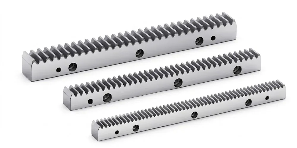
A gear rack is the natural extension of the spur gear in linear positioning systems. The pinion spur gear meshes with the gear rack to convert rotary motor torque into controlled linear displacement along a machine axis — the dominant architecture in CNC machining centre linear axes, gantry robot traversal drives, and automated warehouse stacker cranes. The gear rack module must match the spur gear pinion module for correct meshing geometry, and both components should share the same accuracy grade specification to prevent the rack from becoming the life-limiting element in the drive system. We manufacture gear racks in the same facility as the EP-European Spur Gear series, with fully matched module pitches from Mod.1 through Mod.6.
Frequently Asked Questions — EP-European Standard Spur Gear
Redattore: PXY