
How worm gear speed reducers serve as the mechanical bridge between water turbines and electrical generators in run-of-river, irrigation canal, and pico-hydro installations across the globe.
Small-scale hydroelectric systems — typically defined as installations producing between 1 kW and 10 MW — represent one of the most mechanically demanding environments a gearbox can encounter. The turbine converts kinetic and pressure energy from flowing water into shaft rotation, but turbine output speeds rarely match the synchronous speeds that grid-tied or battery-charging generators require. A ஒற்றை வேகக் குறைப்பான் placed between the turbine shaft and the generator shaft closes this speed mismatch with mechanical precision, converting slow, high-torque turbine rotation into the faster, lower-torque shaft speed the generator needs without electronic speed-control layers that add complexity and failure risk in remote mountain and rural locations.
The worm gear configuration is well suited to this application because its right-angle shaft geometry fits naturally into the compact machine room layouts found at small run-of-river schemes in Nepal, Peru, Scotland, the Philippines, and Colombia. Its inherent self-locking tendency in high-ratio variants prevents the generator from back-driving the turbine during grid disconnection events, a protective behavior that would otherwise require a mechanical brake. This article examines the structural, material, and operational aspects of the ஒற்றை வேகக் குறைப்பான் as it applies to small hydroelectric drive systems, with reference to WP-series worm gear units available across standard frame sizes.
Speed Matching Between Turbine and Generator
A Pelton or Turgo turbine at a pico-hydro site with 40 metres of head might rotate between 300 and 600 rpm at its design operating point. A 4-pole synchronous generator on a 50 Hz grid requires 1500 rpm at the rotor shaft; a 6-pole machine needs 1000 rpm. Without a speed-increasing gearbox between them, the designer faces the choice of a purpose-built slow-speed generator — expensive and difficult to source in remote regions — or an undersized standard generator running off its design point.
ஒரு ஒற்றை நிலை வேகக் குறைப்பான் operating in step-up mode resolves this without bespoke machinery. The worm gear pair is mechanically identical whether driven from the worm or the wheel side; what changes is whether the unit is decelerating a fast input or accelerating a slow one. In step-up service, efficiency and thermal load are slightly higher than in step-down, so frame selection accounts for the heat rejection requirement at the higher input torque of the turbine shaft. WP-series reducers cover ratios from 10:1 to 60:1, giving designers a wide selection of output-to-input speed relationships from a catalog of standard, readily available units.

Manufacturing Structure of WP-Series Single Speed Reducers
The WP-series ஒற்றை வேகக் குறைப்பான் is constructed around an integral one-piece cast housing that is fully machined on a single datum setup. The center distance between the worm shaft axis and the worm wheel shaft axis is machined to IT7 tolerance, ensuring that the tooth contact pattern falls within the design envelope regardless of unit-to-unit variation. This geometric consistency is particularly important in hydropower applications where the unit may remain in service for 15 or more years between major overhauls, and where any progressive change in contact pattern — caused by housing deflection from an inaccurate bore — would gradually shift load toward the tooth edges and accelerate wear.
The worm shaft is machined from chromium-alloy steel bar, thread-hobbed and then ground on the working flank surfaces after case hardening to 58–62 HRC. Post-hardening grinding corrects the distortion introduced by the heat treatment process and restores the lead angle and involute profile to tolerances that determine lubricant film thickness during operation. At the low sliding speeds present in step-up worm drives running from slow turbine shafts, film formation depends almost entirely on surface finish quality — a ground worm surface outperforms a hobbed-only surface in this regime by maintaining the thin hydrodynamic film that prevents bronze-to-steel contact.
Worm wheel rims are cast in phosphor bronze and machined to fit onto a grey-iron hub, with the tooth form generated by a hob that matches the worm’s geometric parameters. The finished assembly is balanced and checked for backlash consistency before housing assembly. End covers are sealed with compressed fiber gaskets and the housing is pressure-tested for oil leakage before leaving the production line — a step that matters because remote hydropower machine rooms may not have easy access to replacement oil or the means to manage an environmental spill near a watercourse.
Material System for Hydropower Drive Conditions
Housing — Cast Iron
HT200 grey cast iron provides the vibration-damping properties that reduce structure-borne noise transmission through the machine room floor. Its thermal conductivity draws heat away from the internal oil bath efficiently, keeping sump temperatures in range even when ambient conditions in a mountain machine room drop below 5°C and the viscosity of mineral oil climbs.
Worm — Alloy Steel
20CrMnTi or 40Cr steel, carburized to case depth 0.8–1.2 mm. The hard case resists the Hertzian contact stresses at the worm-bronze interface; the tough core absorbs the impact torque pulses that turbine rotor imbalance introduces into the drive shaft at running speed.
Worm Wheel — Phosphor Bronze
ZCuSn10Pb1 phosphor bronze, centrifugally cast for a dense outer layer. Bronze yields slightly at local overload peaks — for example, during turbine governor hunting when flow control valves cycle rapidly — rather than fracturing. This plastic compliance extends the life of the tooth contact zone between inspection intervals.
Bearings and Seals
Tapered roller bearings on the worm shaft manage combined axial and radial loads from worm-mesh thrust. Double-lip NBR seals at shaft exits prevent oil loss along the turbine shaft in installations where the reducer sits adjacent to the water channel. Grease-packed labyrinth protection around the input shaft further reduces leakage risk near flowing water.
Drive Options for Small Hydroelectric Systems: A Comparison
| Criterion | Single Speed Worm Reducer | Helical Gear Increaser | Belt and Pulley |
|---|---|---|---|
| Right-angle shaft layout | Native — no adapter needed | Parallel shafts only | Parallel only, offset centers |
| Ratio range (single stage) | 10:1 to 60:1 | 2:1 to 8:1 typical | 1.5:1 to 5:1 practical |
| Back-drive protection | Self-locking at high ratios | None — brake required | None — brake required |
| Noise level | Low — sliding mesh contact | Moderate gear whine | Low running, high slip noise |
| Suitability for high humidity | Sealed cast-iron housing | Sealed housing | Belts degrade in damp conditions |
| Maintenance in remote areas | Oil change only | Oil change + gear check | Belt/tension replacement |
| Efficiency at 20:1 ratio | 78–85% | 92–96% | 88–94% |
Featured Specification: EP-WPKS Single Speed Reducer
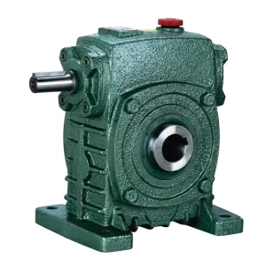
தி EP-WPKS ஒற்றை வேகக் குறைப்பான் is a hollow-shaft, flange-input worm gear drive covering load capacities from 4 to 365 kg. The hollow bore output allows the unit to slide directly onto the generator rotor shaft in installations where a separate coupling would add axial length that the machine room cannot accommodate. The WPKS configuration places the input flange perpendicular to the output shaft, creating the right-angle geometry that suits generator drives where the turbine shaft and generator shaft run at 90 degrees to each other — a common arrangement in compact machine rooms built into dam abutments or hillside penstocks in Scotland, Nepal, and Peru. Available reduction ratios of 10 through 60 give the system designer direct control over the speed step-up factor without requiring non-standard gear pairs or dual-stage arrangements for most pico-hydro and micro-hydro speed ratios.
| அளவுரு | விவரக்குறிப்பு |
|---|---|
| Load Capacity | 4 – 365 கிலோ |
| Input Configuration | Flange-mounted (WPKS type) |
| வெளியீட்டு வகை | Hollow shaft |
| Ratio Options | 10 / 15 / 20 / 25 / 30 / 40 / 50 / 60 |
| Max Input Speed | 1500 r/min |
| வீட்டுவசதி பொருள் | வார்ப்பு இரும்பு |
Step-Up Operation: Running the Worm Gear Reducer in Reverse
The conventional assumption is that a ஒற்றை வேகக் குறைப்பான் in worm configuration accepts fast rotational input at the worm and delivers slow, high-torque output at the wheel. In a hydroelectric step-up application, the roles reverse: the turbine shaft drives the worm wheel at relatively low speed and high torque, and the worm shaft output feeds the generator at a faster, lower-torque speed. This operating mode is sometimes called a worm wheel drive or worm increaser, but the physical unit is unchanged — only the labeling of input and output shifts.
Step-up operation through the worm pair introduces two practical differences from conventional speed reduction service. Mechanical efficiency drops somewhat because the worm thread must now be driven by the wheel rather than the other way around, and the friction geometry is slightly less favorable. For ratios above 20:1, the self-locking characteristic that protects the turbine from being back-driven by the generator disappears as well, because sufficient input torque from the wheel can overcome the mesh friction. At ratios of 10:1 or 15:1, back-drivability varies by unit and lubrication condition, and a check valve or mechanical stop on the turbine shaft may be needed depending on the site electrical protection scheme.
Thermal management in step-up service deserves attention during frame selection. Because the worm wheel is now carrying the high-torque input, the bronze-to-steel contact load is the same as in conventional service but the heat generation is concentrated differently across the mesh. Oil sump temperature rises faster in step-up operation at equivalent power levels, and the system designer should derate the unit by one frame size — or verify the housing surface area is adequate for heat rejection at the ambient temperature of the machine room — before finalizing the installation design.
Lubrication in Remote Hydropower Machine Rooms
Splash lubrication is the norm in WP-series worm reducers, with no oil pump, no filter, and no level sensor to fail in an unmanned machine room. Oil-guiding ribs cast into the housing walls direct splash from the rotating worm wheel into channels that supply the upper thread zone, ensuring full film formation across the mesh even at the low turbine speeds typical of pico-hydro drives. The EP-WPZ and EP-WPKZ models — covering oil capacities from 0.4 to 5.2 litres — are sized to provide the sump volume needed for adequate heat rejection at sustained turbine-generator duty in moderate ambient conditions.
ISO VG 220 synthetic gear oil is the standard fill for a ஒற்றை வேகக் குறைப்பான் for remote sites where oil changes must be infrequent. Polyalphaolefin-based synthetic oil maintains viscosity stability across the temperature swings a mountain machine room experiences between winter shutdown and summer full-load operation — a range that mineral oils handle less consistently. Extended drain intervals of 5,000–7,000 operating hours are achievable with synthetic oil and documented by regular sampling, minimizing the number of times maintenance personnel must reach a remote site by foot or vehicle.
Water contamination of the oil bath is a specific risk at hydro sites where seal wear or housing condensation can introduce moisture from the high-humidity air surrounding the penstock and turbine housing. A moisture-detection oil sample at each scheduled maintenance visit catches this early. If the oil emulsifies, the lubricant film breaks down and bronze-to-steel contact scoring follows rapidly. Housing interiors primed with rust-inhibiting paint and sealed with silica gel breather plugs reduce condensate formation between operating cycles.
Mounting and Installation Configurations
Foot Mount — WPA / WPS
Bolted to a machined concrete or steel pad in the machine room. Suited when the turbine and generator shafts are at 90 degrees with adequate floor area for the gearbox footprint. Shimmed base plates allow fine alignment correction without moving the turbine or generator.
Flange Input — WPDS / WPKS
Turbine shaft couples directly to the worm wheel input face via an input flange adapter. Eliminates the flexible coupling and its periodic inspection. Common in generator-on-turbine-shaft configurations at Philippine and South American micro-hydro projects where space is limited.
Hollow Shaft Output — WPKA / WPKS
The hollow bore slides onto the generator rotor shaft directly, removing a coupling stage. Useful when the generator manufacturer’s shaft diameter falls within the standard hollow bore range. Reduces the axial stack height of the complete drive train in compact machine rooms.
Vertical Shaft — WPDKA
Covers loads from 5 to 350 kg. Suited to vertical-axis turbine configurations where the turbine runner is submerged and the generator sits above on a vertical shaft. The oil sump orientation must be confirmed against the WPDKA installation manual to ensure adequate oil level at the worm mesh.

Site-Specific Considerations: Highland, Tropical, and Arid Climates
Small hydroelectric projects span a wide range of climatic conditions. A run-of-river scheme in the Scottish Highlands operates year-round, including periods of sub-zero ambient temperature where oil viscosity at startup is a concern. A tropical mountain site in Colombia or the Philippines experiences high humidity and warm temperatures that accelerate corrosion on unprotected iron surfaces. A site in a semi-arid canyon in Peru may have moderate temperatures but seasonal dust contamination that blocks housing breather vents.
For Scottish and Nordic highland sites, synthetic ISO VG 220 oil prevents cold-start oil starvation. The cast-iron housing itself does not contract enough at sub-zero temperatures to affect bearing preload, but the oil becomes viscous enough to delay splash distribution to the upper worm. Pre-heating the machine room or using a sump heater element during cold starts is standard practice on sites below −10°C. A single speed worm reducer in this condition should be allowed to circulate oil at low load for five minutes before full turbine load is applied.
இணக்கமான இயக்க முறைமைக் கூறுகள்
A complete hydroelectric drive system integrates the ஒற்றை வேகக் குறைப்பான் with a matched generator motor and, where double-stage ratios are required, a full-range worm gearbox from the same design family. Sourcing all drive components from one manufacturer eliminates mounting incompatibilities and simplifies spare-parts logistics for sites with difficult road access in Indonesia, Nepal, or Peru.


உற்பத்தியாளரைப் பற்றி
The product catalogue spans agricultural gearboxes, worm gear reducers, planetary gear drives, power take-off shafts, hydraulic cylinders, gears, chains, and motors — covering mechanical power transmission for industrial and agricultural markets across six continents. Production facilities are certified to ISO 9001:2015, with documented process controls from incoming material inspection through final functional testing.
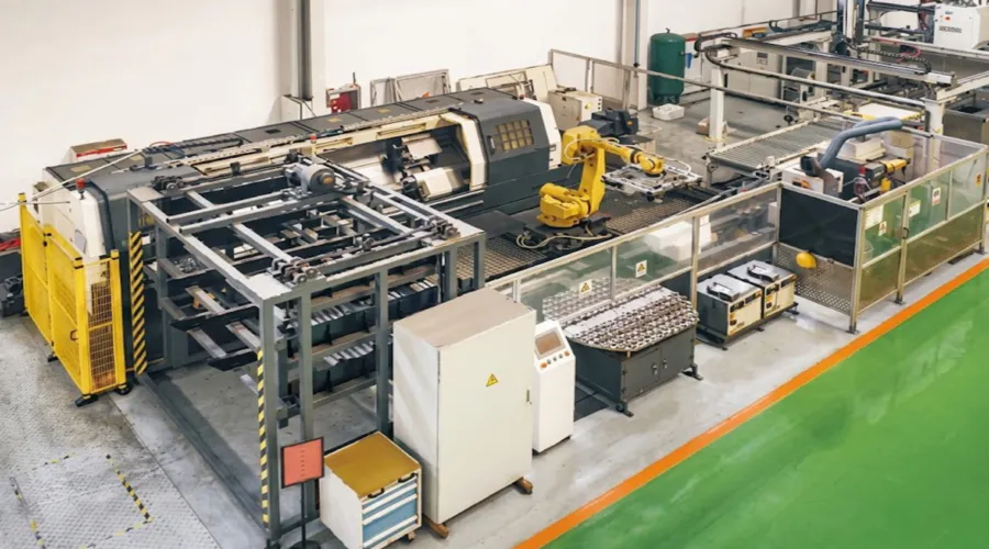
In-house manufacturing covers precision casting in ductile iron, grey cast iron, cast steel, precision cast steel, and cast aluminum; gear hobbing, shaping, and surface grinding; induction and carburizing heat treatment; and full assembly with leak and load verification. Standard and non-standard gears, sprockets, worm gears, pulleys, shafts, and mechanical sub-assemblies are produced to customer drawings or developed from catalog configurations, supporting OEM procurement and aftermarket supply in more than 60 countries.
பட்டறை



அடிக்கடி கேட்கப்படும் கேள்விகள்
பதிப்பாசிரியர்: PXY