
Textile & Garment Manufacturing
Drive architecture, material selection, and maintenance considerations for worm gear reducers deployed across weaving machinery in global textile production.
Industrial looms — whether shuttle, rapier, air-jet, or water-jet type — operate under a duty profile that places specific and often underestimated demands on the drive system components positioned between the motor and the weaving mechanism. Shedding drives, let-off tension systems, take-up beam drives, dobby and jacquard head mechanisms, and selvedge yarn carriers all require speed reduction from the prime motor to their operating shaft speeds. In cotton and synthetic fiber weaving, the precision of the let-off and take-up ratio directly influences fabric density and tension consistency across the full warp beam width.
ஒரு ஒற்றை வேகக் குறைப்பான் based on a worm gear transmission addresses these requirements with a geometry that fits the spatial constraints of loom frames, delivers high reduction ratios without compound staging, and provides the self-locking characteristic that prevents warp beam back-drive during emergency stops or power interruptions — a quality particularly important in synthetic fiber weaving where warp tension loss causes irreversible yarn distortion.
This page examines how the worm single speed reducer is structured, what material system drives its performance in textile environments, and how its operating characteristics align with the drive requirements of industrial cotton and synthetic fiber looms across key textile manufacturing regions including India, Turkey, Italy, and Bangladesh.

உற்பத்தி கட்டமைப்பு
The housing of a worm single speed reducer is produced as an integrated casting, typically in grey cast iron for standard loom drive positions and in ductile iron where the mounting arrangement carries substantial radial shaft loads — as is the case on warp beam let-off drives where the beam diameter and yarn tension combine to generate significant overhung loading at the output shaft. Precision-cast aluminium alloy housings are used on compact mounting positions such as selvedge tucking mechanisms and dobby cam follower drives where unit mass must be kept low.
The worm shaft and worm wheel are arranged at a 90-degree intersection, producing a right-angle output from the motor input. In a loom frame, this geometry allows the motor to run longitudinally along the loom side frame while the driven shaft extends transversely into the beam, shedding mechanism, or take-up roll. Avoiding an additional bevel stage or chain redirection simplifies the drive train and reduces the number of coupling and sprocket interfaces that require periodic adjustment.
Bearing seats, shaft journals, and the bore for the worm wheel hub are finish-machined after casting to hold close concentricity tolerances. Looms in synthetic fiber production often run at higher speeds than cotton looms — rapier looms for polyester or nylon may reach 600 to 900 picks per minute — and at these rates even marginal shaft misalignment generates measurable asymmetric bearing loading that shortens service life. Housing geometry held to manufacturing tolerance is the upstream control that prevents this failure mode.
பொருள் அமைப்பு
The worm is produced from 20CrMnTi or 40Cr alloy steel, case-carburised and precision-ground to a tooth surface finish in the Ra 0.6 to 0.8 range. Against this hardened steel worm thread, the worm wheel uses a centrifugally cast tin-bronze or phosphor-bronze rim mounted on a ductile iron or cast steel hub. The bronze wheel material carries significant advantages in a weaving environment: the conformable nature of tin-bronze allows progressive bedding between the worm and wheel tooth flanks during the initial running-in period, enlarging the contact patch and reducing peak contact stress before the unit reaches its rated continuous load.
In synthetic fiber weaving, airborne fiber and lint accumulation around drive components is a persistent environmental factor. Bronze wheel material is less susceptible to abrasive surface damage from contaminated oil than equivalent hardened steel wheel designs, particularly once fine synthetic fiber has migrated into the oil bath through a degraded seal. Well-sealed WP-series housings with double-lip output shaft seals and a gasketed cover joint reduce the rate of contamination ingress, but the bronze wheel’s tolerance of marginal lubrication conditions provides an additional margin against accelerated tooth wear.
Housing surface treatment on textile machinery drive units often specifies a chemical-resistant topcoat to resist the sizing agents, lubricants, and dye carriers used in finishing and preparation sections adjacent to the weaving shed. Polyurethane topcoats over epoxy primer provide adequate chemical resistance for most textile plant environments. Shaft seal selection — lip seal for most positions, labyrinth plus contact seal for units mounted in orientations where fiber accumulation on the seal lip is a known maintenance issue — is made at the unit specification stage rather than as a field retrofit.

Drive Point Applications Across Industrial Loom Types
The table below maps principal drive stations on cotton and synthetic fiber looms to the characteristics of the worm single speed reducer that make it a suitable fit at each position.
| ஓட்டுநர் நிலை | Loom Type | Reducer Fit Factor |
|---|---|---|
| Warp beam let-off shaft | All types | Self-lock prevents back-drive on power interruption; high-torque output at low speed |
| Take-up roll drive | Rapier, air-jet, water-jet | Fixed ratio maintains precise cloth density (picks per cm) at constant output speed |
| Dobby head cam drive | Dobby loom | Compact right-angle unit fits within head housing; single reduction avoids compound staging |
| Selvedge yarn carrier drive | Rapier, air-jet | Low power band (0.12–0.75 kW); aluminium housing minimises added mass on loom side frame |
| Cloth roll beam drive | All types | Hollow shaft output mounts directly on beam shaft; eliminates separate shaft coupling |
| Warp stop motion advance | All types | Intermittent duty; self-lock holds detector bar position between advances |
| Jacquard head drive shaft | Jacquard loom | Right-angle output suits overhead mounting; ratio matches pattern repeat cycle to loom pick rate |
Key Technical Parameters — WP Series Worm Single Speed Reducer
The parameters below reflect the operating range of the WP-series worm single speed reducer range applicable to cotton and synthetic fiber loom drives. Unit selection for a specific loom drive position should be based on required output torque, ratio, and mounting configuration.
| அளவுரு | Typical Range | Textile Application Note |
|---|---|---|
| உள்ளீட்டு சக்தி | 0.12 – 15 கிலோவாட் | Spans selvedge carrier to warp beam let-off drives |
| Speed Ratio | 5:1 – 100:1 | Single stage; matches most loom auxiliary drive ratio requirements |
| எண்ணெய் கொள்ளளவு | 0.4 – 5.2 L | Splash lubricated; no oil pump or filter circuit required |
| Output Orientation | Right-angle (90°) | Motor runs longitudinally; output shaft feeds beam or roller transversely |
| வீட்டுவசதி பொருள் | Cast iron / Ductile iron / Cast aluminium | Grade matched to radial load and unit mass requirements |
| Worm Wheel Rim | Tin-bronze / Phosphor-bronze | Tolerates marginal lubrication from lint-contaminated oil better than steel wheel |
| Mounting Options | Foot, flange, hollow shaft | Hollow shaft eliminates coupling on beam shaft installations |
| Max Input Speed | 1500 rpm (50 Hz) / 1800 rpm (60 Hz) | Direct coupling to IEC induction motor standard in textile plants globally |
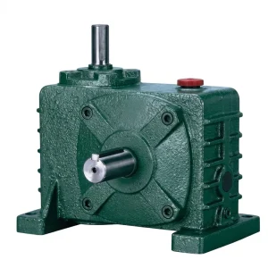
Highlighted Product: EP-WPZ Series
Self-Locking Behaviour and Warp Tension Management
The self-locking characteristic of a worm single speed reducer at reduction ratios above approximately 30:1 — where the worm lead angle falls below the friction angle of the mesh — is a property with direct practical value on loom let-off systems. When loom motion stops suddenly due to a warp break detection, an emergency stop signal, or a power interruption, the warp beam must not be allowed to unwind freely. In a synthetic fiber warp — polyester, nylon, or viscose — uncontrolled back-drive of the beam releases tension instantaneously across the full warp width, causing the warp threads to lose their ordered shed separation and potentially snapping yarns or causing warp thread entanglement that requires manual re-threading.
A worm single speed reducer with a ratio above 30:1 holds the beam shaft stationary under load without requiring a separate electromagnetic brake or mechanical backstop device. This is a configuration that simplifies the let-off drive assembly, reduces the number of electrically powered brake components requiring maintenance, and removes one potential point of failure in the emergency stop chain — a consideration of real weight in textile plants in Italy and Turkey where loom availability directly determines shift output.
On take-up systems, the same fixed-ratio characteristic ensures that the cloth beam advances at a rate precisely proportional to the motor speed and the set ratio, maintaining a consistent picks-per-centimetre density across the woven cloth regardless of fluctuations in the loom’s mechanical loading. Deviation in take-up speed — which can occur with variable-ratio or belt-and-sheave transmission systems under changing load — produces visible weft density variation (barre defects) in the finished cloth, a quality issue that leads to fabric downgrade in end markets from apparel to industrial textile applications.

Lubrication Considerations in Weaving Shed Environments
The weaving shed is not a clean industrial environment. Sizing starch, finishing agents, short fiber lint, and airborne humidity from humidification systems used to maintain yarn tensile strength all present contamination risks to drive unit lubricants. The splash lubrication system of the worm single speed reducer keeps the oil volume sealed inside the housing during normal operation, but long-term seal degradation allows environmental contamination to migrate into the oil bath and accelerate wheel tooth wear.
ISO VG 220 worm gear oil suits most textile loom auxiliary drives operating in the ambient temperature range of 18 to 35 degrees Celsius typical of humidified weaving sheds. Synthetic polyalkylene glycol (PAG) formulations provide better demulsibility — the ability to shed water rather than forming an emulsion — which is advantageous in sheds with high airborne humidity. Drain intervals for mineral EP oil in this environment typically run to 2000 – 3000 operating hours; synthetic PAG oil extends this to 5000 – 7000 hours.
Oil capacity across the WP series spans 0.4 to 5.2 litres, which means the volume involved in an oil change is modest and the procedure — drain plug, refill to sight glass level, replace drain plug — is achievable in a brief loom stoppage during a planned maintenance window. The small oil volume also means a single contamination event, such as an influx of sizing spray during a beam change, does not represent a large cost to address — drain, flush, refill.
Noise Level and Vibration in a Loom Hall Context
Industrial loom halls are inherently high-noise environments — shuttle looms can exceed 100 dB(A) at the operator position, and even modern shuttle-less looms in high-density configurations run in the 85 to 95 dB(A) range. Against this background, the noise contribution of individual drive units is rarely the dominant factor in the overall acoustic environment, but it can become significant when a worm single speed reducer is mounted on a structure that radiates noise into an adjacent quiet zone such as a preparation area, inspection room, or office.
The worm gear mesh, owing to its sliding contact character rather than impact-like engagement, generates a smooth, relatively low-frequency noise signature compared to spur or helical gear pairs transmitting equivalent power. After the running-in period, a well-lubricated and correctly aligned worm single speed reducer in the 0.12 to 15 kW range operates with a noise level typically below 75 dB(A) at one metre from the housing under rated load — a characteristic that makes it one of the quieter options available for auxiliary drive positions on textile machinery where noise reduction without acoustic enclosures is desirable.
தொடர்புடைய தயாரிப்புகள்
The single speed reducer functions most effectively as part of a coordinated drive system. Two product families that are commonly specified alongside this reducer type on industrial loom installations are shown below.


எங்களைப் பற்றி
The manufacturing range includes agricultural gearboxes, worm gear reducers, planetary gear drives, power take-off shafts, hydraulic cylinders, gears, chains, and motors. The production facility carries ISO 9001:2015 certification. Design and manufacturing capability extends to industrial and agricultural gearbox assemblies in ductile iron, cast iron, cast steel, precision cast steel, and cast aluminium, together with gears, sprockets, worm gears, pulleys, worms, shafts, and both standard and non-standard mechanical components produced to customer drawings or established dimensional standards for textile and industrial machinery OEM and aftermarket programmes worldwide.
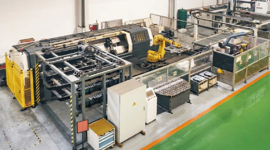
பட்டறை



அடிக்கடி கேட்கப்படும் கேள்விகள்
பதிப்பாசிரியர்: PXY