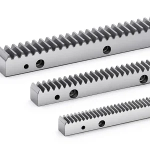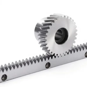
Thanh răng xoắn EP-24x24x1000 — Thanh răng tuyến tính chính xác M2 DIN6
A gear rack is a straight, toothed bar that meshes with a pinion gear to convert rotary motion into linear motion — or vice versa. The rack and pinion gear system is one of the most mechanically efficient methods of achieving controlled linear travel, and the helical variant takes that principle further by distributing tooth engagement across an angled profile. This reduces noise, extends component life, and supports higher load ratings compared to a conventional straight gear rack or spur gear rack.
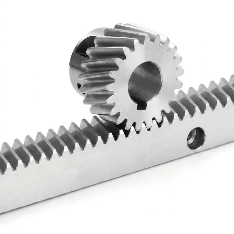
The EP-24x24x1000 is manufactured to a 24 mm cross-section width and height, with a full rack length of 1000 mm. The helical tooth profile runs at a right-hand helix angle of 19°31′42″ — a geometry that provides progressive tooth contact, quieter operation, and a notably smoother force transfer than a standard spur rack. Whether you are engineering a high-cycle CNC gantry, a rack and pinion linear slide, or an automated conveyor positioning axis, this rack module is built to maintain dimensional integrity across long operating periods.
PRECISION POWER TRANSMISSION
Thanh răng xoắn EP-24x24x1000 — Thanh răng tuyến tính chính xác M2 DIN6
Cái EP-24x24x1000 gear rack is a precision-engineered helical gear rack designed for demanding linear motion applications across automation, CNC machining, robotics, and industrial positioning systems. With a module M2 specification, 150 helical teeth at a 19°31′42″ helix angle, and DIN6 GB5 precision grade, this linear gear rack delivers consistent, low-backlash motion in environments where accuracy and durability are non-negotiable.
Thông số kỹ thuật
The table below consolidates the full parameter set for the EP-24x24x1000 helical rack. These figures are referenced against DIN standards and verified through our in-house quality inspection process before any unit leaves the production floor. Engineers sourcing a linear rack and pinion solution will find all critical mating dimensions — tooth module, pressure angle, and addendum coefficient — specified here to facilitate direct integration into existing gearbox rack and pinion designs.
| Tham số | Giá trị | Note |
|---|---|---|
| Người mẫu | 552020100 | Factory model number |
| Specification (W×H×L) | 24 × 24 × 1000 mm | Cross-section width × height × length |
| Module (Mudule) | M2 | Metric module sizing |
| Số răng | Z = 150 | Total helical teeth on full rack length |
| Pressure Angle | α = 20° | Standard involute pressure angle |
| Addendum Coefficient | ha = 1 | Standard full-depth tooth |
| Tooth Profile | Helical Teeth | Angled for smooth, progressive mesh |
| Helix Angle (Right-hand) | 19°31′42″ | Right-hand helix direction |
| Precision Grade | DIN6 GB5 | German/Chinese dual-standard grading |
| Surface Hardness (HRC) | HRC 48–52° | High-frequency induction hardening |
| Production Process | Four-side grinding + tooth surface grinding | Dual finishing for tight tolerances |
How a Helical Gear Rack Works
The operating principle of the gear rack and pinion system is elegantly simple: a circular pinion with matching tooth geometry rolls along the teeth of the gear rack, converting the pinion's rotational motion into straight-line displacement. The distance the rack travels per pinion revolution is directly determined by the gear ratio of rack and pinion — in this case governed by the M2 module, where one full pinion rotation advances the rack by π × module × number of pinion teeth millimeters.
What sets the helical variant apart from a spur gear rack hoặc straight gear rack is the angled tooth geometry. Rather than engaging along the full tooth face simultaneously — which generates an abrupt load spike and elevated noise — the helical rack engages progressively. Each tooth contact begins at one edge and sweeps across the tooth width as the pinion advances. This overlap distributes load across multiple teeth at any given instant, reducing per-tooth stress and enabling higher torque transmission for the same cross-sectional footprint.
The 19°31′42″ helix angle on the EP-24x24x1000 is carefully chosen to balance the beneficial overlap ratio against the axial thrust forces that helical geometry introduces. This makes the helical rack and pinion system well-suited for precision rack and pinion linear slide assemblies, gantry systems, and any linear axis where low vibration and consistent positioning repeatability are essential. The surface-hardened tooth flanks at HRC 48–52° retain this geometry under cyclic loading far longer than unhardened equivalents.
Năm lợi thế hiệu suất chính
Manufactured and verified against DIN6 and GB5 dual standards, the EP-24x24x1000 delivers tooth-pitch accuracy that keeps positioning error to a minimum across the full 1000 mm rack length. This level of control is critical for CNC machine tools and automated positioning axes where cumulative error directly affects output quality.
Tooth surfaces are hardened to HRC 48–52° using induction hardening, concentrating hardness precisely at the contact zone while preserving toughness in the rack body. This treatment dramatically extends service life on high-cycle applications without introducing the brittleness of through-hardened components — a key advantage when the rack and pinion gear operates under variable or shock loads.
The 19°31′42″ helical tooth angle provides gradual, overlapping tooth engagement that substantially reduces transmission noise and vibration versus a spur-tooth design. For factory environments requiring lower acoustic output, or precision instruments sensitive to mechanical vibration, this characteristic of the helical rack and pinion geometry translates into a measurable operational benefit.
Unlike rack products that apply grinding only to the tooth flank, the EP-24x24x1000 undergoes both full four-side body grinding and dedicated tooth surface grinding. This dual-finishing approach produces a rack with tightly controlled squareness on all mounting faces — critical when the linear gear rack needs to be bolted directly to a machined guideway or linear bearing carriage without shimming.
The M2 metric module is one of the most widely adopted specifications in industrial rack and pinion gear systems globally, making it straightforward to source a matching gearbox rack and pinion pinion or driven gear. Whether you're integrating into an existing rack pinion gear drivetrain or specifying a new axis from scratch, the M2 module provides broad component availability across markets in Europe, Asia, and North America.
Material & Quality Standards
The EP-24x24x1000 gear rack is produced from high-grade carbon steel selected for its balanced combination of machinability, strength, and response to surface heat treatment. The base material provides sufficient core toughness to absorb dynamic loads and impact events without fracture, while the induction-hardened tooth surface achieves HRC 48–52° to resist the abrasive wear that shortens the life of softer rack teeth in continuous-duty applications.
Production follows a multi-stage manufacturing sequence: raw material is cut and rough-machined before heat treatment, then the hardened blank is finish-ground on all four body faces. Tooth surface grinding follows as a separate dedicated operation — this sequencing ensures that post-hardening distortion is fully corrected before the tooth profile geometry is finalized. The resulting rack meets DIN6 GB5 pitch-accuracy requirements, which translates to a real-world cumulative pitch error that supports high-precision positioning on both short and extended travel axes.
Our manufacturing facility holds ISO 9001:2015 certification. Inspection of each production batch includes dimensional checks on tooth pitch, tooth profile form, and body squareness — giving buyers confidence that the gear rack they receive matches the published specification rather than a nominal target.
Các kịch bản ứng dụng
The versatility of the gear rack and pinion mechanism means the EP-24x24x1000 finds a home across a broad range of industrial sectors. Below are the primary areas where this linear gear rack is commonly specified.
On CNC milling machines, routers, and plasma cutting tables, the rack and pinion linear slide drives gantry axes where travel distances exceed the practical range of ballscrews. The helical tooth profile reduces chatter at the cutter, and the ground tooth surface keeps positioning repeatability within acceptable tolerances for both roughing and finishing passes.
Cartesian robot linear axes, pick-and-place gantries, and transfer systems rely on reliable linear rack and pinion drives to move payloads at high cycle rates. The EP-24x24x1000 provides the rigidity and surface hardness required to maintain accuracy over millions of cycles — a practical requirement in automotive and electronics assembly lines running two or three shifts continuously.
Conveyor diverters, sliding gates, stopper arms, and indexing tables in packaging lines use rack gear pinion drives for their compact profile and ability to generate high linear force from a small servo motor. The M2 module specification balances force capacity with compactness, making the EP-24x24x1000 appropriate for moderate-speed, medium-force material handling equipment.
In rack and pinion press configurations, where a rotating input shaft drives a vertically traveling ram through a pinion rack gear interface, precise tooth geometry determines press force consistency and positioning accuracy. The ground tooth profile of the EP-24x24x1000 reduces binding and ensures even force distribution throughout the press stroke.
Precision positioning stages in medical imaging equipment, laboratory automation, and optical inspection systems benefit from the low noise and smooth motion characteristic of a helical rack and pinion gear drive. The DIN6 GB5 accuracy grade supports sub-millimeter positioning requirements that are common in life-science and semiconductor inspection instruments worldwide.
Stage platforms, elevator counterbalance systems, bridge dam gates, and construction hoists use heavy-duty gear rack drives where alternatives like hydraulic cylinders or chain drives lack the positional control or service accessibility required. The surface-hardened tooth flanks withstand the shock loading common in outdoor or structurally dynamic applications.
Sản phẩm liên quan & Khả năng tương thích hệ thống
MỘT gear rack rarely operates in isolation. The performance of the complete linear axis depends on choosing compatible mating components — from the drive pinion to the supporting guide system. We supply a range of complementary products that pair directly with the EP-24x24x1000, enabling a single-source procurement approach that simplifies specification and reduces supplier coordination overhead.
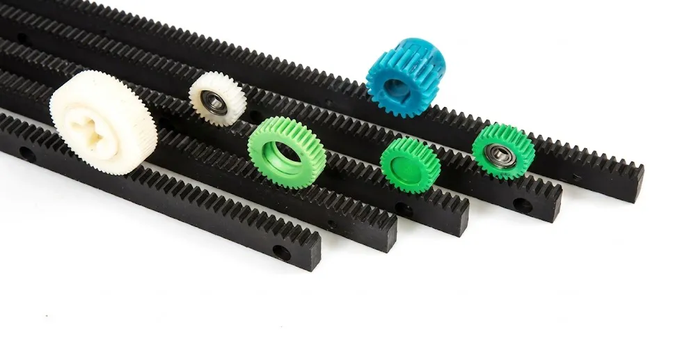
Where weight reduction, corrosion immunity, or reduced noise are priorities, our plastic gear rack range offers a practical alternative. These racks share compatible tooth module sizing with the EP-24x24x1000, allowing designers to specify metal racks on high-load axes and polymer racks on lighter or moisture-exposed axes within the same machine — a one-supplier solution for mixed-material rack systems.
The EP-24x24x1000 helical rack is designed to mesh with a matching helical pinion gear. Our full range of Helical Gear products covers a broad span of tooth counts and bore sizes, making it straightforward to select a pinion that delivers the required linear travel speed and torque multiplication for your rack and pinion gear axis. Sourcing both the rack and the helical pinion from one production facility ensures accurate tooth-geometry matching — no compatibility guesswork between suppliers.

Thông tin về nhà sản xuất
With more than a decade of hands-on experience in mechanical power transmission, our production team specializes in precision gear and drivetrain components for industrial and agricultural equipment worldwide. Our product range spans agricultural gearboxes, worm gear reducers, planetary gear drives, power take-off shafts, hydraulic cylinders, gears, chains, and motors — all manufactured under a single ISO 9001:2015 certified quality management system.
We design and produce a broad portfolio of industrial and agricultural gearbox assemblies in materials including ductile iron, cast iron, cast steel, precision cast steel, and cast aluminum. Our standard parts program covers gears, sprockets, worm gears, pulleys, worms, shafts, and a wide variety of non-standard mechanical components specified to customer drawings. For buyers sourcing a custom gear rack or a complete gearbox rack and pinion assembly, we offer engineering support through the specification, prototype, and production phases.
Xưởng




Câu hỏi thường gặp
Meta Description:
EP-24x24x1000 M2 helical gear rack, DIN6 GB5 precision, HRC 48–52° surface hardening, 150 teeth — ideal for CNC, robotics, and rack and pinion linear slide applications.
Biên tập viên: PXY