
General Buyer Guides & Comparison
A straightforward reference for engineers, procurement teams, and plant managers buying a speed reducer for the first time — or switching gearbox types for an existing drive application.
What Is a Single Speed Reducer?
A single speed reducer is a mechanical power transmission device that converts a motor’s input speed to a lower output speed at a fixed ratio, while simultaneously increasing the output torque by approximately the same ratio (adjusted for efficiency losses). The term “single speed” means there is exactly one gear ratio between input and output — the device does not shift, switch, or change ratio during operation. Once a single speed reducer is installed with a given motor, the output shaft rotates at one specific speed for every input speed the motor delivers. This simplicity is both the defining characteristic and the primary functional advantage of the design.
In practical terms, what is a single speed reduction gear doing on a machine? It is answering a fundamental mismatch: electric motors are most efficient and cost-effective when they run at their rated synchronous speed — typically 960, 1,450, or 2,900 RPM depending on pole count and supply frequency. But the conveyors, mixers, pumps, augers, and actuators that these motors drive need to run at 5 to 300 RPM. The single speed reducer bridges that gap in one mechanical stage, without the additional complexity, weight, and cost of a multi-ratio transmission. Buyers across industries in the United States, Germany, Australia, India, and Southeast Asia specify the single speed reducer as the default drive solution for fixed-speed applications precisely because it is simpler, more reliable, and less expensive to maintain than any alternative that achieves the same function.

Manufacturing Structure & Material System
The Housing
In a WP-series worm gear single speed reducer, the housing is cast from grey iron (HT200 or HT250 depending on size) and machined on all bearing seats and mating faces. The housing does two things: it holds the internal components in precise geometric alignment, and it forms the oil-tight enclosure that keeps the lubricant in and contamination out. A good housing is rigid enough not to flex under rated torque — flexure causes bearing misalignment, which accelerates fatigue — and has enough external surface area to dissipate the heat generated by gear mesh losses through convection to the surrounding air.
The Worm and Wheel
The gear set in a single stage right-angle worm-gear speed reducer consists of two elements: the worm (a cylindrical shaft with helical threads, connected to the input) and the worm wheel (a throated gear with teeth that mesh with the worm threads, connected to the output). The worm is typically 20CrMnTi alloy steel, carburised and case-hardened to HRC 56–62, and CNC-ground on the thread flanks after hardening. The worm wheel rim is ZCuSn10P1 tin-phosphor bronze, centrifugally cast and hobbed to the final tooth form. This steel-on-bronze pairing achieves the low friction, quiet operation, and long wear life that makes a worm speed reducer the preferred choice for moderate-torque applications across many industries globally.
Bearings and Shafts
Input and output shafts are supported on rolling element bearings — deep-groove ball bearings on the input side for radial loads, paired tapered roller or angular-contact bearings on the output side for combined radial and thrust loads from the worm mesh reaction. Shaft material is medium-carbon alloy steel. Key seats are machined to standard DIN or AGMA dimensions for direct coupling to motors and driven machines. Bearing fits are machined to H7 tolerance on the housing bore and k6 on the shaft, providing a light interference fit that holds the bearing ring against fretting under dynamic loading.
Seals, Oil, and Venting
Lip seals at each shaft exit keep oil inside and contamination out. Standard seals are NBR (nitrile rubber), suitable for mineral oil at temperatures up to 100°C. FKM (Viton) seals are available for higher temperatures or chemically aggressive environments. Every worm gear reducer gearbox includes a breather vent to prevent pressure build-up from thermal cycling of the oil volume — a detail that low-quality units sometimes omit, leading to seal extrusion failures. The oil fill level is set by the position of the fill/drain port, which varies with mounting orientation and must be checked in the installation drawing.
Single Speed Reducer vs Multi-Speed Gearbox: The Core Differences
The question buyers most commonly ask is whether they need a single speed reducer or something that can change ratio on the fly. The honest answer is that the majority of industrial applications — conveyor drives, pump drives, mixer drives, lift tables, auger feeders, gate actuators — operate at one speed for their entire working life. The motor runs, the gearbox transmits the power at a fixed ratio, and the driven machine turns. A variable-ratio transmission in this context adds mechanical complexity, procurement cost, and maintenance burden without providing any functional benefit. The single speed gear reducer is not a compromise or a budget option for these applications — it is the correct engineering choice.
A multi-speed gearbox makes engineering sense when the application genuinely requires different gear ratios during operation: a machine tool spindle that needs low gear for heavy cuts and high gear for finish passes, a vehicle transmission that must accelerate from rest and then sustain highway speed, or a test rig that simulates multiple operating conditions in sequence. These are fundamentally different functional requirements, and the additional mechanical complexity of a multi-ratio transmission is justified by the application. For the wide majority of fixed-speed industrial drives that procurement teams in the United Kingdom, Canada, Brazil, and India encounter daily, it is not.

Side-by-Side: Single Speed Reducer vs Multi-Speed Gearbox
Use this table as a starting point for the selection decision. The right choice depends on the specific application requirements, not on a general preference for one type over the other.
| Characteristic | ஒற்றை வேகக் குறைப்பான் | Multi-Speed Gearbox |
|---|---|---|
| Number of output speed settings | One (fixed) | Two or more (switchable) |
| Mechanical complexity | குறைந்த | High |
| Parts count | Fewer | More |
| Maintenance requirement | Oil changes, seal inspection | Above plus shift mechanism, synchronisers |
| Self-locking at high ratios | Yes (worm type, ratio >1/30) | No — requires separate brake |
| Best application fit | Fixed-speed continuous drives | Variable-duty or vehicle drives |
| Available ratio range (worm type) | 1/5 to 1/60 in one stage | Multiple bands, gear-shifted |
| VFD compatibility for speed adjustment | Yes — combined with VFD input | Depends on design |
Worm Gear vs Helical vs Planetary: Which Single Speed Reducer Type Is Right?
Within the single speed reducer category, the buyer must also choose between gear configurations. The three most common are the worm gear reducer, the helical gear reducer, and the planetary gear reducer. Each has a distinct combination of characteristics that suits it to certain applications and not others. Understanding the difference prevents the mistake of specifying a premium helical or planetary unit for an application where a worm speed reducer would perform equally well at lower cost — or conversely, specifying a worm unit for an application where its efficiency limitations would cause thermal problems.
The worm gear speed reducer is the most widely used single speed reducer type in the moderate-torque, fixed-speed industrial applications that represent the largest buying segment globally. Its 90° input-to-output angle eliminates the need for a separate bevel gear stage to change shaft direction; its single-stage ratio range of 1/5 to 1/60 covers the majority of industrial speed reduction requirements; and its self-locking at high ratios removes the need for a secondary brake in lift and gate applications. The trade-off is efficiency — a worm gear reduction at 1/40 typically achieves 60–68% mechanical efficiency compared to 96–98% for a comparable helical stage. For low-duty or intermittent drives, this efficiency gap is inconsequential. For a motor running 24 hours per day at significant power, the helical or planetary single stage speed reducer may be the more economical choice when total energy cost is included in the selection calculation.
How to Read a Single Speed Reducer Nameplate and Data Sheet
First-time buyers often find single speed reducer data sheets confusing because they list parameters in an unfamiliar format. Understanding three core values makes the data sheet readable: the reduction ratio, the rated output torque, and the rated input power. The reduction ratio (expressed as 1/N, e.g., 1/20 or 1/40) tells you how many rotations of the input shaft produce one rotation of the output shaft. Divide your motor speed by this ratio to get the output shaft speed. The rated output torque is the maximum continuous torque the gearbox can transmit at the output shaft — compare this against the torque demand of your driven machine with an appropriate service factor applied. The rated input power is the maximum motor power the gearbox can accept at rated input speed.
Secondary parameters to check include the oil volume (important for installation in non-standard orientations), the shaft dimensions (Q for input bore diameter in flange-type units, LS and S for output shaft diameter and length), the key section dimensions (T×V for input, W×Y for output), and the mounting bolt pattern dimensions. These determine whether the unit physically fits in the installation space and connects to the motor and driven machine without adaptor plates. Buyers at Australian agricultural equipment dealers and Indian industrial distributors frequently overlook shaft key dimensions and discover at installation that the output shaft keyway does not match the driven sprocket hub — checking this at the quotation stage takes two minutes and avoids a week of delay. For the complete dimensional data across all ratio and size options, visit the single speed reducer range.

Single Speed Reducer Models Referenced in This Guide
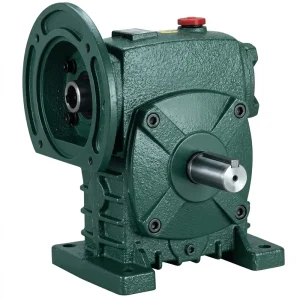
EP-WPDS Single Speed Reducer (0.12–15 kW)
The WPDS is a flange-input worm gear single speed reducer with direct IEC motor face mounting — the most compact motor-gearbox arrangement available in the WP series. It covers 0.12 to 15 kW input power across housing sizes from 40 to 250, with ratios from 1/5 to 1/60 available within a single housing size. The direct flange interface removes coupling alignment variables and reduces the total drive axial envelope — making this the standard specification for applications where space is constrained or where frequent motor replacement makes coupling alignment a maintenance burden. Suitable for first-time buyers specifying a single speed reducer for a light-to-medium-duty conveyor, feeder, or lift table application.
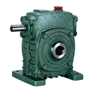
EP-WPKS ஒற்றை வேகக் குறைப்பான் (4–365 கிலோ)
The WPKS is the heavy-duty variant in the WP single speed reducer range, designed for applications where the output shaft carries combined radial and axial loading — lift table drives, transfer mechanisms, heavy mixer drives, and direct-coupled pump drives where the driven shaft imposes thrust loads on the gearbox output. Unit weights from 4 to 365 kg indicate the range from small-platform lift drives to the main drive of large industrial mixing or handling equipment. The WPKS reinforced output shaft bearing arrangement handles the combined loading that would cause premature failure in a standard WP unit. At ratios of 1/30 and above, the WPKS provides inherent self-locking — the mechanical hold-in-place feature that most lift table and gate drive applications depend on.
Products That Work Alongside a Single Speed Reducer
A single speed reducer is rarely the only component that needs specifying. The motor on the input and the coupling or sprocket on the output both need to be matched to the gearbox’s shaft dimensions and rated torque. Below are two categories of compatible product that buyers regularly source at the same time as the single speed reducer.
மின்சார மோட்டார்கள்
The motor is the first component in the drive train and must be matched to the single speed reducer’s input shaft dimensions, flange type, and rated input power. IEC B3 and B5 frame motors from IE2 and IE3 efficiency classes are the standard input for WP-series single speed reducers in industrial applications across Europe, Australia, and Southeast Asia.

புழு கியர்பாக்ஸ்
For applications requiring a different mounting configuration or a compact NMRV-type housing rather than the WP-series flange-foot format, the broader worm gearbox range provides additional options. NMRV units cover very small powers (down to 0.06 kW) in an aluminium housing; heavy industrial WP units cover up to 15 kW in cast iron. Both families use the same worm gear principle as the WP-series single speed reducer.

Manufacturing Background
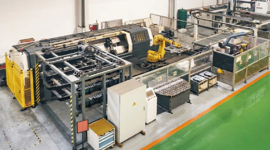
Our production covers worm gear reducers, industrial gearboxes, planetary drives, power take-off shafts, hydraulic cylinders, gears, chains, and motors — the full range of mechanical power transmission components needed to specify complete drive packages without coordinating across multiple suppliers. The facility is ISO 9001:2015 certified, with gear cutting, heat treatment, CNC tooth grinding, and assembly all conducted in-house under documented quality controls.
We design and manufacture standard and custom gearboxes and assemblies in ductile iron, grey cast iron, cast steel, precision investment cast steel, and cast aluminium. Our component catalogue includes gears, sprockets, worm gears, pulleys, worm shafts, and non-standard transmission parts produced to customer drawings. Buyers in the United States, United Kingdom, Canada, Australia, India, and Southeast Asia source single speed reducer units from us for agricultural, industrial, and commercial equipment applications.
பட்டறை



அடிக்கடி கேட்கப்படும் கேள்விகள்
Q1. What is the difference between a single speed reducer and a variable-speed gearbox for a conveyor drive in a Canadian food processing plant?
A single speed reducer delivers one fixed output speed for every input motor speed — if your motor runs at 1,450 RPM and the gearbox has a 1/30 ratio, the output shaft turns at approximately 48 RPM regardless of any other factor. A variable-speed gearbox (or a VFD controlling the motor upstream of a fixed-ratio single speed reducer) allows the output speed to be adjusted within a range. For most food processing conveyor drives in Canada, the combination of a single speed reducer with a variable-frequency drive on the motor is the standard and most practical arrangement: the single speed reducer provides the main ratio, and the VFD allows the line speed to be adjusted between product runs without changing any mechanical component. This is simpler to maintain, more reliable, and generally more cost-effective than a mechanically variable-ratio gearbox for the same application.
Q2. How do I know what single speed reduction gear ratio I need for my application when buying a worm gear reducer for the first time in Australia?
The required ratio equals your motor’s rated speed divided by the required output shaft speed. If your motor runs at 1,450 RPM and your conveyor head shaft needs to turn at 50 RPM, you need a ratio of 1,450 ÷ 50 = 29 — so you would select a 1/30 ratio single speed reducer (the nearest standard ratio). For most Australian industrial applications using 50 Hz four-pole motors, the calculation starts from 1,450 RPM. The output speed you need comes from your driven machine — for a conveyor, it is the required belt or chain speed divided by the sprocket pitch circle radius. For a mixer, it is the recipe speed in RPM. If you cannot find the required output speed in the machine documentation, measure the current gearbox output shaft speed with a tachometer if the machine is currently running, or contact the machine OEM for the specification.
Q3. What are the disadvantages of a worm gear single speed reducer compared to a helical gearbox for a continuous-duty pump drive in the United Kingdom?
The primary disadvantage of a worm gear speed reducer compared to a helical unit for a UK continuous-duty pump drive is mechanical efficiency. A worm gear reducer at a 1/20 ratio typically achieves 72–80% efficiency; a comparable helical stage achieves 96–98%. The difference represents power lost as heat — for a 5.5 kW motor input, a worm unit wastes 1.1–1.5 kW as heat versus approximately 0.1–0.2 kW for a helical. At UK electricity rates and across 8,000 hours per year of continuous operation, this efficiency gap has a measurable cost. For pump drives where the motor runs continuously at significant power, a helical gearbox’s higher efficiency justifies its higher unit cost over a 3 to 5 year operating horizon. The worm gear single speed reducer remains the better choice for applications that are intermittent, require self-locking, need a right-angle shaft configuration at low cost, or operate at power levels where the efficiency difference is negligible in absolute energy terms.
Q4. How do I install a single speed worm gear reducer correctly for the first time in an Indian agricultural equipment application?
Correct worm gear reducer installation follows four steps: mount, fill, align, and commission. First, mount the gearbox on its base or flange in the orientation shown in the installation drawing — orientation determines which port is the fill, which is the drain, and where the vent sits. Second, fill the oil to the correct level for the mounting orientation before running the unit — an unfilled gearbox will destroy the worm wheel within minutes. Use ISO VG 220 worm gear oil unless the ambient temperature in your location (Indian field conditions can reach 40–45°C ambient) suggests a synthetic grade for better thermal stability. Third, align the input motor shaft or coupling to the gearbox input shaft within 0.05 mm parallel offset. Fourth, run the unit unloaded for 15–30 minutes and check for oil leaks, unusual noise, or housing temperature above approximately 80°C before connecting the driven load. The first oil change should occur at 500 hours to remove running-in metallic particles.
Q5. Which single speed reducer series should a US equipment manufacturer choose when sourcing a customised gearbox for a new agricultural conveyor product line?
For a US agricultural conveyor OEM developing a new product line, the starting point is the conveyor drive torque and speed requirement — derive these from the belt pull force, head pulley diameter, and required belt speed. The WPDS series (0.12 to 15 kW, flange input) suits light-to-medium auger and chain conveyor drives where the motor mounts directly to the gearbox for a compact package. The WPKS series is appropriate for heavier applications with higher output shaft loads — grain elevator head drives, drag conveyor drives, or heavy auger drives where shock loading from frozen or compacted material is a recurring condition. Both series support OEM customisation including non-standard shaft diameters, modified keyways, and private-label arrangements. For a new product line, requesting sample units for prototype testing before committing to a production batch is strongly recommended, and documentation of ISO 9001 certification and material traceability should be confirmed at the sample stage for any US OEM subject to product liability requirements.
பதிப்பாசிரியர்: PXY