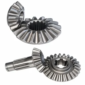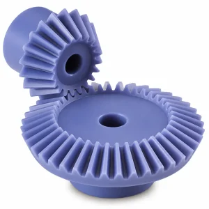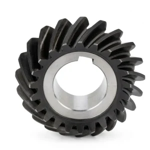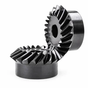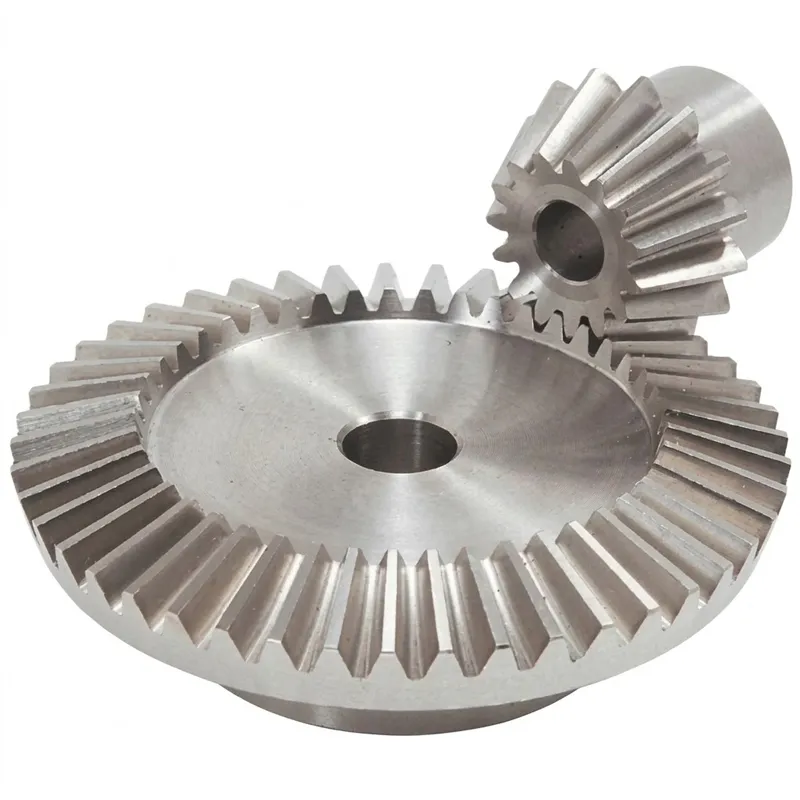
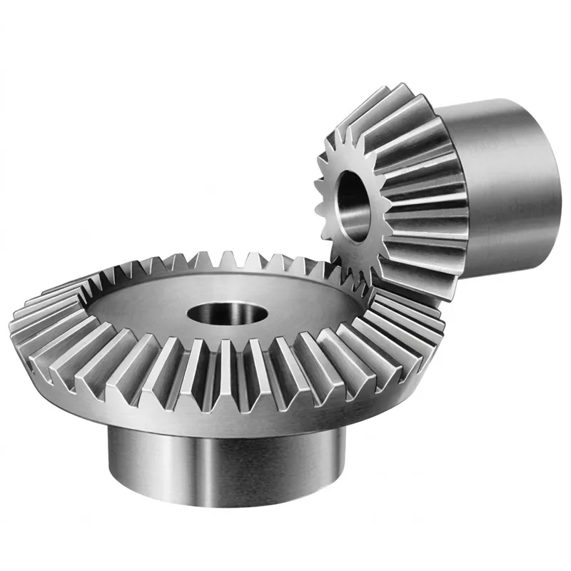
EP-Straight Bevel Gear
Cái EP-Straight Bevel Gear series offers precision-engineered transmission solutions for diverse industrial applications, including automatic control machines, semiconductor equipment, medical devices, solar energy systems, and machine tools. Available in standard modules such as M3, M4, M5, M8, and M12, these gears are manufactured from versatile materials including Brass, C45 Steel, Stainless Steel, Copper, POM, Aluminum, and Alloy. To ensure optimal performance and durability, teeth can be hardened, milled, or ground, achieving high precision grades of DIN6 through DIN9 with tolerances ranging from 0.001mm to 0.1mm. Comprehensive surface treatments are available, including Zinc/Nickel plating, Passivation, Oxidation, Anodizing, Geomet, Dacromet, Black Oxide, Phosphatizing, Powder Coating, and Electrophoresis. Compliant with ISO, DIN, ANSI, JIS, and BS standards, these components support custom non-standard designs.
EP-Straight Bevel Gear — Dependable Right-Angle Transmission Across Industrial Sectors
When an application calls for angular power transmission that is robust, straightforward to manufacture, and compatible with a broad range of shaft intersection angles, the straight bevel gear remains the most direct engineering answer. The EP-Straight series covers modules M3, M4, M5, M8, M12, and beyond, machined from brass, C45 steel, stainless steel, copper, POM, aluminum, alloy steel, and additional materials to tolerance grades DIN6 through DIN9.
Whether your system requires a compact straight bevel pinion for a medical imaging arm, a robust straight tooth bevel gear for a solar tracker drive, or a precisely ground wheel for a semiconductor handling machine, this product line delivers the dimensional accuracy, surface treatment options, and multi-standard compliance that global OEM and MRO buyers rely on. Read through the specifications, working principle, material data, and application guidance below to confirm the right configuration for your project.
Product Specification — EP-Straight Bevel Gear Series
The following table summarizes the core technical parameters for the EP-Straight series. Custom module, material, surface treatment, and precision grade combinations are available on request.
| Tham số | Thông số kỹ thuật |
|---|---|
| Product Type | Straight Bevel Gear (Straight Tooth Bevel Gear) |
| Model Number | M3, M4, M5, M8, M12 and etc. (custom module available) |
| Vật liệu | Brass, C45 steel, Stainless steel, Copper, POM, Aluminum, Alloy, and others |
| Xử lý bề mặt | Zinc-plated, Nickel plated, Passivation, Oxidation, Anodization, Geomet, Dacromet, Black Oxide, Phosphatizing, Powder Coating, Electrophoresis |
| Standard | ISO, DIN, ANSI, JIS, BS, Non-standard |
| Độ chính xác | DIN6, DIN7, DIN8, DIN9 |
| Teeth Treatment | Hardened, Milled, or Ground |
| Tolerance | 0.001 mm – 0.01 mm – 0.1 mm |
| Finish Options | Shot/sandblast, heat treatment, annealing, tempering, polishing, anodizing, zinc-plated |
| Items Packing | Plastic bag + Cartons or Wooden Packing |
| Payment Terms | T/T, L/C |
| Production Lead Time | 20 business days for sample / 25 days for bulk |
| Samples | Available; sample express shipping cost borne by client |
| Ứng dụng | Automatic controlling machines, semiconductor industry, general industry machinery, medical equipment, solar energy equipment, machine tools |
How Does a Straight Bevel Gear Work? Mechanism and Engineering Principle
MỘT straight bevel gear is a conical gear whose teeth are generated along straight radial lines — lines that, if extended, converge at the apex of the pitch cone. Two mating straight tooth bevel gear members are mounted so their pitch cones share a common apex, and when one cone rolls against the other, rotational motion and torque are transferred smoothly between shafts intersecting at a defined angle. The most common intersection angle in industrial use is 90°, though non-right-angle configurations are achievable by adjusting the individual cone angles of each member.
The fundamental geometry means that each tooth on a straight bevel gear tapers in both height and thickness from the large end (heel) to the small end (toe) of the face width. Tooth contact begins and ends at one side of the face rather than progressing gradually across it the way a helical tooth does — a characteristic that produces a brief, distinct load pulse per tooth engagement cycle. This is the primary reason that straight and spiral bevel gear configurations are chosen differently: spiral variants spread the load over multiple teeth simultaneously for quieter running, while straight-tooth versions are simpler to manufacture, easier to align, and entirely appropriate wherever noise is managed at the system level rather than the gear level.
Cái gear ratio of bevel gear sets is established by the tooth count ratio between pinion and wheel. A 12-tooth straight bevel pinion driving a 48-tooth wheel produces a 4:1 reduction — the output shaft turns at one-quarter the input speed while carrying four times the torque (less friction losses). Because the cone geometry constrains proportional tooth sizing, practical single-stage ratios generally fall in the 1:1 through 5:1 range for straight bevel configurations, with higher ratios requiring two stages or a switch to worm or planetary arrangements.
Hiểu về difference between helical and bevel gear is useful context for anyone specifying EP-Straight products: helical gears transfer torque between parallel shafts using inclined teeth that engage gradually, while bevel gears transfer torque between intersecting shafts by rolling conical pitch surfaces against each other. Where both axis change and minimal noise are priorities, spiral bevel gears are the natural choice; where the axis change is the main need and quiet operation is handled through housing design or operating speed limits, the straight bevel gear offers the practical advantage of easier setting and lower tooling cost.
Key Advantages of the EP-Straight Bevel Gear
Wide Material Range
From brass and copper for low-load instrument drives to C45 steel, alloy steel, and stainless steel for structural machinery applications — the EP-Straight series covers the full spectrum. POM and aluminum variants extend the range into lightweight and chemically sensitive environments, giving designers genuine flexibility rather than forcing a compromise between material property and gear form.
Precision to DIN6–DIN9 with Tolerance to 0.001 mm
Tooth form accuracy grades DIN6 through DIN9 cover the range from high-precision positioning drives down to general-purpose power transmission. The achievable dimensional tolerance of 0.001 mm to 0.1 mm — depending on grade and process — means that engineers specifying precision bevel gear components for semiconductor handling, machine tools, and medical equipment can confidently source from this series without secondary finishing operations.
Comprehensive Surface Treatment Options
Zinc-plated, nickel-plated, passivation, oxidation, anodization, Geomet, Dacromet, black oxide, phosphatizing, powder coating, and electrophoresis coatings are all available on the EP-Straight series. This breadth of surface treatment options means the straight bevel gear can be tailored for corrosion resistance in marine environments, appearance quality in consumer products, or electrical insulation in electronics assembly equipment without requiring a separate part number.
Multi-Standard Compliance: ISO, DIN, ANSI, JIS, BS
Standard compliance spanning ISO, DIN, ANSI, JIS, and BS — plus non-standard configurations on request — means that an OEM designing equipment for simultaneous sale in North America, Europe, and Asia can source a single straight bevel gear system specification that satisfies all regional requirements. This avoids the engineering and qualification overhead that arises when parallel regional supplier lists are maintained.
Material Options for EP-Straight Bevel Gears
Material selection shapes every performance characteristic of a straight bevel gear — load rating, wear life, corrosion resistance, and machinability all flow from this choice. Our EP-Straight line spans eight material families so that engineers working across different sectors and load regimes can specify the right combination rather than accepting a catalogue default that may be over- or under-engineered for their application.
C45 steel is the workhorse material for medium-load industrial straight tooth bevel gear applications. It machines cleanly, accepts surface hardening by induction or flame methods, and offers a reliable mechanical property baseline across temperature ranges typical of indoor industrial environments. For applications involving sustained high torque — machine tool drives, general industrial gearboxes — C45 steel with a hardened tooth surface provides cost-effective performance that keeps the gear in service across extended maintenance intervals.
Alloy steel grades are selected when core toughness, higher hardenability in larger cross-sections, or elevated fatigue resistance are needed — situations common in heavy automation, construction equipment sub-assemblies, and agricultural machinery final drives. The exact alloy designation is matched to the duty cycle: chromium-molybdenum grades for deep case hardening, nickel-chromium grades where impact resistance is the critical property alongside surface wear. Stainless steel is specified when the straight bevel gear operates in wet, food-grade, or chemically aggressive environments where carbon or alloy steel would pit or stain — pharmaceutical manufacturing equipment and marine deck machinery are the most common use cases.
Brass and copper variants are used in low-load, low-speed instrument drives and electrical equipment where non-magnetic and non-sparking properties are needed alongside reasonable dimensional precision. They are common in automatic controlling machines and precision gauging instruments. Aluminum straight bevel gears provide the lightest-weight option with good corrosion resistance, making them a natural fit for solar energy tracking mechanisms and portable equipment where drivetrain weight directly affects structural or power-supply sizing. POM (polyoxymethylene / acetal) gears occupy the self-lubricating, chemically inert niche — clean rooms, medical equipment, and electronic assembly stations all benefit from a gear that runs dry without contaminating the surrounding environment.
Regardless of material, the tooth treatment options — hardened, milled, or ground — allow the gear surface condition to be matched to the precision grade required. Ground teeth at DIN6 tolerance produce the closest-fit mesh and lowest vibration; milled teeth at DIN8 or DIN9 are appropriate where the duty cycle is light and manufacturing economy is the primary concern.
Straight Bevel Gear vs Spiral and Zerol — Choosing the Right Tooth Form
The three main bevel tooth forms each have a natural application domain. The straight bevel gear uses teeth that radiate straight from the cone apex; contact begins and ends abruptly across the full face width of each tooth, which generates some vibration and noise at higher pitch-line velocities but is mechanically straightforward and tolerant of minor alignment errors. This makes the straight cut bevel gear the default choice for low-to-medium speed applications and for situations where maintenance or replacement in the field by non-specialist technicians is anticipated.
Cái zerol bevel gear is a special case: it has curved teeth like a spiral bevel but at zero mean spiral angle, so the teeth technically cross the cone apex in the same way as a straight bevel. Zerol bevel gears offer smoother engagement than straight-tooth designs — closer in behavior to a spiral bevel — while remaining compatible with straight bevel housing geometry. They are specified when a designer needs quieter performance than a standard straight bevel gear can provide but must retain the existing housing and shaft design without modification.
Among the recognized bevel gear advantages of the straight-tooth form are: simpler cutting with a straight bevel cutter rather than the more complex tooling needed for spiral forms; lower tooling investment for short production runs or custom modules; and more straightforward alignment verification using tooth contact pattern checks without the twist-direction ambiguity present in spiral-tooth sets. When comparing the bevel gear vs spur gear for an application, the axis-change capability of the bevel is the decisive factor — no spur gear configuration can redirect a drive shaft by 90°.
Where EP-Straight Bevel Gears Are Applied
Cái straight bevel gear appears wherever a reliable angular drive is needed across a compact envelope. Below are the main sectors served by the EP-Straight series, each with specific engineering requirements the product line is built to address.
⚙ Automatic Controlling Machines
Servo-driven positioning stages, rotary index tables, and multi-axis robotic wrists all incorporate straight bevel gear pairs at the axis-change points. The tight tolerance grades available in this series — down to DIN6 with 0.001 mm dimensional control — ensure that the angular positioning accuracy of the drive is not compromised by gear geometry error. Brass and stainless variants handle the non-magnetic requirements common in electronic assembly automation and precision metrology equipment.
🔬 Semiconductor Industry Equipment
Wafer handling robots, lithography stage drives, and inspection system gantries operate in cleanroom environments where particle generation, lubrication contamination, and non-magnetic requirements rule out many standard gear materials. POM and aluminum straight bevel gear options run dry, generate minimal particulate, and are available in non-magnetic grades that do not disturb sensitive magnetic field measurements during inline inspection processes.
⚕ Medical Equipment
Surgical robot arm joints, imaging system positioning drives, and rehabilitation device actuators all use angular gear stages where noise, lubrication-free operation, and biocompatibility are priorities. Stainless steel and POM straight tooth bevel gear variants meet the cleaning and sterilization requirements of medical environments while providing the positional precision that patient safety demands. Sample qualification is supported with full dimensional report documentation.
☀ Solar Energy Equipment
Single-axis and dual-axis solar tracker drives use straight bevel gear sets at the axis intersection where the primary horizontal drive meets the panel tilt adjustment mechanism. Aluminum variants are standard in tracker applications, combining corrosion resistance with a mass saving that reduces the structural load on tracker mounting frames — a real cost factor when multiplied across large utility-scale solar farms in Australia, the UK, Brazil, and other markets with aggressive solar deployment targets.
🔧 General Industry & Machine Tools
CNC milling head drives, drilling machine quill feeds, and grinding wheel dresser mechanisms all incorporate straight bevel gear pairs to redirect the servo or spindle motor axis into the working direction. C45 steel or alloy steel gears ground to DIN6 are the standard specification here, providing the combination of tooth accuracy, surface hardness, and shaft bore precision that machine tool builders require to meet their own accuracy and vibration specifications.
🌐 General Industrial Machinery
Conveyor diverters, packaging line crossover drives, irrigation pump right-angle heads, and marine deck equipment all represent bevel gear examples from everyday industry where a reliable, maintainable angular drive is needed without demanding the cost of spiral bevel tooling. The broad module range — M3 through M12 standard, other modules on request — covers the spectrum from small conveyor drives to medium-duty pump stations in a single consistent product line.
About Us — Over Ten Years of Precision Gear Manufacturing
Our manufacturing operations have accumulated more than a decade of focused experience in mechanical power transmission — long enough to have worked through the failure modes, the material selection edge cases, and the application-specific tolerance requirements that only years of real production exposure reveal. The product portfolio spans agricultural gearboxes, worm gear reducers, planetary gear drives, PTO shafts, hydraulic cylinders, transmission gears, roller chains, and electric motors, giving our engineering team broad context when advising on straight bevel gear selection and system integration.
All production runs under ISO 9001:2015 quality management certification, covering the complete process from incoming material verification through CNC machining, heat treatment, surface finishing, and final inspection before packing. Beyond standard catalogue items, we design and produce custom gearbox assemblies in ductile iron, cast iron, cast steel, precision-cast steel, and cast aluminum. Sprockets, worm gears, pulleys, worm shafts, and non-standard mechanical components are all within scope, making us a viable single-source supplier for industrial buyers who want to reduce the number of vendors they qualify and manage.
For buyers in Germany, Canada, South Korea, Australia, and other technically demanding markets seeking verified precision bevel gear manufacturers with clear documentation, drawing-based customization capability, and dependable logistics, we offer T/T and L/C payment terms and sea, air, or express shipping. Technical review before order confirmation is available at no charge, and dimensional inspection records accompany every shipment on request.
Xưởng




Compatible Products — Complete Drivetrain, Single Source
MỘT straight bevel gear stage rarely operates in isolation. We manufacture the following complementary gear types to the same quality and precision standards, enabling buyers to consolidate their drivetrain sourcing and eliminate cross-supplier tolerance stack-up issues.
Bánh răng xoắn kép
In drivetrains where a parallel-shaft stage precedes or follows the straight bevel gear stage, double helical (herringbone) gears eliminate the axial thrust force that single-helix designs impose on bearing housings. Specifying both the straight bevel pair and the double helical stage from one source ensures that module, pressure angle, and heat treatment records are coordinated across the full drivetrain — simplifying the assembly validation process and providing a single accountability chain if any dimensional non-conformance arises during integration testing.

Giá đỡ bánh răng
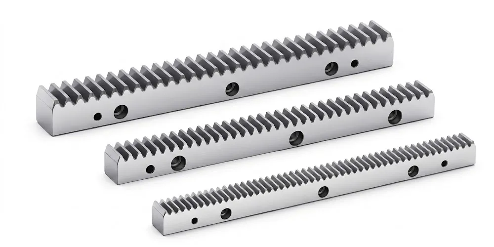
Linear actuation stages interfacing with rotary straight bevel gear drives require gear racks matched in module and pressure angle to the associated pinion. Our gear rack production covers the standard modules used throughout the EP-Straight bevel series, supporting CNC axis drives, solar tracker linear actuators, industrial lifting columns, and automated gate systems. Sourcing both the rack and the straight bevel gear set from one facility eliminates the tolerance mismatch and mixed certification documentation that arise when components are pulled from separate supply chains.
Trade & Delivery Information — Gear Products
The following trade terms, lead times, and MOQ policies are specifically mapped to gear-type products (gears, pinions, worm gears, bevel gears, helical gears, ground gears) based on our general trading framework. Only clauses directly referencing gear products have been extracted from the full terms library.
Lead Time
Based on the standardisation level, machining complexity, and processing requirements of gear products:
| Gear Products — Lead Time Reference | |
|---|---|
| Product Category | Estimated Lead Time |
| Standard Transmission Gears | 10–25 working days |
| Standard Gears + Simple Processing | 15–35 working days |
| Custom Machined Gears | 20–45 working days |
| High-Precision / Heat-Treated Gears | 30–60 working days |
Trade Types
Recommended Incoterms based on product volume, weight, value, and urgency for gear products:
| Gear Products — Recommended Trade Terms | |
|---|---|
| Product Type | Recommended Terms |
| Standard Gears | EXW / FOB / CIF / DAP |
| Custom / OEM Gears | EXW / FOB / CIF / DAP |
FCA, CFR, CPT, CIP and DDP terms are also available upon specific request and subject to negotiation.
MOQ
Minimum order quantities for gear products are determined by product type, material, processing requirements, and batch size:
| Gear Products — MOQ Guidelines | |
|---|---|
| Product Category | MOQ Policy |
| Custom Gears | MOQ depends on drawing, material, tolerance, machining process and batch size. |
| Heat Treatment / Surface Treatment | Special processing may be limited by process batch size. |
General Terms
The following baseline terms apply to all gear product orders:
| General Trading Terms | |
|---|---|
| Term | Policy |
| MOQ Principle | Flexible based on product type and order value. |
| Sample Policy | New customers may apply for 1–5 samples where suitable. |
| Mixed Orders (Consolidation) | Combination of different models supported; total order value should reach approximately USD 1,500. |
| Small Orders | 1–2 pcs orders supported, but unit price may be relatively higher. |
| Overall Delivery Time | Standard parts: 10–25 working days | Custom components: 20–45 working days | Project equipment: 45–120 working days |
| Overall Trade Terms | EXW, FOB, CIF, DAP supported as standard; FCA, CFR, CPT, CIP and DDP available upon specific negotiation. |
Frequently Asked Questions — Straight Bevel Gear
Q1. What material should engineers in the semiconductor industry in North America specify for a straight bevel gear running dry in a cleanroom wafer handling robot?
For cleanroom wafer-handling applications, POM (acetal / polyoxymethylene) is the most commonly specified material for a straight bevel gear running dry. POM self-lubricates through its own polymer structure, generates minimal particulate during mesh engagement, and is entirely non-magnetic — all critical requirements when operating near electromagnetic sensors and precision measurement equipment in semiconductor fabs. Where higher load or higher temperature is a factor alongside cleanroom requirements, aluminum is an alternative; it is lighter than steel, anodizes to a very hard, particle-resistant surface, and is also non-magnetic. If the application involves direct exposure to aggressive cleaning solvents between maintenance cycles, stainless steel with a passivation surface treatment is the reliable choice, combining chemical resistance with the mechanical strength needed for continuous-duty robotic motion.
Q2. How does a straight bevel gear differ from a zerol bevel gear and when would a machine tool builder in Germany choose one over the other?
The key difference lies in the tooth curvature. A straight bevel gear has teeth whose centerline runs straight from the heel to the toe, producing abrupt full-face-width contact that generates more vibration at higher speeds. A zerol bevel gear has curved teeth — similar in form to a spiral bevel — but with a zero mean spiral angle, so the hand of the spiral cancels out and the gear can be used in a housing designed for a straight bevel without producing net axial thrust. A German machine tool builder would typically specify a zerol bevel when upgrading an existing spindle head drive to reduce noise and vibration without redesigning the housing — the zero-spiral geometry fits the existing straight bevel mounting envelope while delivering spiral-like smooth engagement. For a new design where the housing can be dimensioned from scratch, a proper spiral bevel or the straight bevel gear would be chosen based on speed and noise target.
How do I correctly install a straight bevel gear pair in a solar tracker drive to get the right tooth contact and avoid premature wear in outdoor desert environments?
Lắp đặt đúng cách một straight bevel gear pair in a solar tracker starts with confirming that the housing shaft intersection angle exactly matches the gear cone angle — any angular deviation shifts the contact patch toward one end of the tooth face, concentrating stress and accelerating wear. After assembly, apply marking compound to the pinion teeth and rotate under hand pressure; the contact pattern should appear centrally on the tooth height and cover roughly 50% of the face width under no-load conditions. In desert outdoor environments, sealing against sand ingress is as important as gear alignment — abrasive contamination inside the gear mesh accelerates tooth flank wear several times faster than normal adhesive wear. Specify a housing with IP65 or better sealing when deploying straight bevel gear systems in Middle Eastern, Australian outback, or North African solar installations. Use aluminum gear variants where the structural weight of the tracker frame benefits from drivetrain mass reduction.
Which precision grade of straight bevel gear is appropriate for a medical imaging arm positioning drive used in European hospital equipment subject to CE machinery directive?
Medical imaging arm drives typically require a straight bevel gear at DIN6 or DIN7 precision grade. DIN6 is appropriate when the positioning repeatability specification of the arm is tight — sub-millimeter at the imaging sensor — because the tighter pitch error and runout tolerances at this grade directly limit the angular transmission error that translates into positional scatter at the arm tip. DIN7 is acceptable for drives where the arm's overall mechanical compliance (flex in the arm structure itself) dominates positional error and the gear is not the limiting factor. From a CE machinery directive standpoint, the key documented requirement is not the DIN grade itself but the noise emission level and vibration evidence, both of which improve with closer gear accuracy. Ground tooth surfaces at DIN6 with stainless steel material and passivation finish also satisfy the cleaning protocol demands of hospital environments, where equipment surfaces must withstand repeated disinfectant wipe-down without surface degradation.
Where can OEM buyers in Australia or South Korea source custom straight bevel gear sets in M5 or M8 with full material certification and sample support before bulk commitment?
OEM buyers in Australia, South Korea, and other export markets can order custom EP-Straight straight bevel gear sets directly through our export program. We accept customer engineering drawings in standard 2D or 3D CAD formats — DWG, STEP, IGES — and produce sample units within 20 business days for qualification testing before any bulk purchase commitment. Material mill certificates, heat treatment process records, and dimensional inspection data sheets accompany samples and bulk orders on request. Shipments to Australia and South Korea are routed via DHL, FedEx, or sea freight depending on urgency and volume. Payment by T/T or L/C is supported. Bulk orders ship in 25 days from confirmed order. A drawing review consultation at no charge is available before production begins to confirm module, bore tolerance, surface treatment, and precision grade are correctly specified for the application.
Biên tập viên: PXY