
Oil, Gas & Offshore Engineering
Application of Single-Speed Gear Reducers
in Offshore Platform Mooring Winch Drives
A technical reference for offshore and marine engineers specifying worm gear speed reducers in mooring winch drive systems — covering manufacturing structure, material systems, corrosion protection, load-holding behavior, and winch drive selection for deepwater and shallow-water platforms worldwide.
Mooring Winch Drives on Offshore Platforms — The Role of the Speed Reducer
Offshore platform mooring systems depend on winches to manage anchor lines, riser tensions, and positioning cables under sustained dynamic loading from waves, current, and wind. Every winch in that system — whether on a fixed jacket structure in the North Sea, a semi-submersible in the Gulf of Mexico, or an FPSO vessel off West Africa — requires a drive train that delivers high torque at low speed, holds load without drift when the motor is de-energized, and survives the marine environment without corrosion degrading its mechanical performance.
The single speed reducer sits at the heart of this drive train. By passing motor output through a precision worm-and-wheel mesh, the single stage speed reducer converts the high-speed, low-torque characteristics of a standard electric motor into the low-speed, high-torque output that a drum-type mooring winch requires to haul, pay out, and hold anchor chain or wire rope under the loads that offshore positioning demands. The single reduction geometry accomplishes this in one compact stage — without intermediate shafting that adds length, weight, and additional alignment points to an already congested winch skid.
For offshore mooring service specifically, the worm gear speed reducer brings two mechanical properties that other reducer types cannot match at the same combination of ratio and compactness. The first is the inherent self-locking tendency of high-ratio worm gearing, which prevents the winch drum from back-driving under mooring load when the motor is off. The second is the worm mesh’s natural resistance to shock — the sliding contact between the worm thread and wheel tooth distributes and damps the impulse loads that snap-loading events on anchor chains or wire ropes would otherwise transmit directly to the motor shaft and drive couplings. Understanding these two properties is the starting point for engineers evaluating a single speed reducer for offshore mooring winch duty, and both are explored in detail throughout the sections below.

Manufacturing Structure
The WP-series single speed gear reducer is built on a matched worm shaft and worm wheel assembly enclosed in a precision-machined housing. The worm shaft is manufactured from case-hardened alloy steel — typically 20CrMnTi — surface-ground to a lead accuracy that keeps transmission error below levels perceptible at the winch drum. The worm wheel combines a phosphor-bronze alloy tooth ring with a cast-iron or steel center hub, the bronze chosen for its compatibility with steel counterfaces under the sliding contact regime that worm gearing demands, and for its tolerance of the boundary lubrication conditions that can develop on a winch drive during slow-haul and load-holding phases.
The housing is cast and then precision-machined as a matched assembly — both bearing bores are machined in a single setup to guarantee shaft-to-shaft alignment geometry under the thermal cycling and dynamic loading that offshore winch drives experience through a full deployment-to-retrieval cycle. Foot and flange mounting faces conform to ISO and DIN reference dimensions, allowing direct bolt-up to standard IEC motor flanges and to winch drum gearbox mounting pads without custom adapters.
WP-series reducers used in mooring winch service are typically configured with the output shaft pointing downward or horizontally toward the drum — a mounting orientation that the housing accommodates through multiple configurable output shaft faces. Each housing includes a fill port, drain plug, and oil-level reference point accessible from the outside, so lubrication checks can be performed without removing the reducer from the winch skid frame.
20CrMnTi case-hardened alloy steel, surface-ground for lead accuracy. Transfers full motor torque to the worm wheel through sliding mesh engagement.
Phosphor-bronze alloy ring on cast-iron hub. Bronze provides inherent lubricity and tolerates boundary lubrication during load-hold and slow-haul operating modes.
Taper roller bearings on the output shaft handle combined axial and radial loading from winch drum tension and rope fleet angle forces in offshore mooring service.
Matched-bore machining in a single setup. Multiple output shaft face options cover downward, horizontal, and inclined drum orientations on winch skid frames.
Material System for Marine and Offshore Environments
Marine and offshore environments impose corrosion demands that do not appear in land-based industrial applications. Salt-laden humid air, occasional seawater spray, and the accelerated electrochemical attack that occurs in splash zones all require housing materials, surface treatments, and sealing systems that go beyond what a standard industrial reducer delivers in a sheltered factory environment. Getting the material specification right for an offshore mooring winch single speed reducer is not a cosmetic decision — it directly determines how many years of service the unit delivers before a first major maintenance intervention is required.
Cast gray iron housings provide the structural rigidity and vibration damping baseline for the WP series, but in offshore service they are typically specified with epoxy or two-component polyurethane topcoats applied over a zinc-rich primer — a coating system that is compatible with the cathodic protection regimes used on most steel-structure offshore platforms. Ductile iron variants offer improved impact toughness when the winch skid is subject to dropped-object risk or crane loads during anchor-handling operations. Where weight budgets on topside structures are tight, cast aluminum alloy housings eliminate iron corrosion risk entirely while reducing unit weight by 40–60% compared to equivalent iron castings.
| Component | Standard Material | Offshore / Marine Alternative | Selection Reason |
|---|---|---|---|
| Housing | Gray cast iron | Cast aluminum / Ductile iron | Aluminum removes iron corrosion risk; ductile iron handles impact loading during anchor handling |
| Surface Coating | Oil-resistant alkyd enamel | Zinc-rich primer + epoxy topcoat | Offshore platform corrosion systems require coatings compatible with cathodic protection regimes |
| Worm Shaft | 20CrMnTi alloy steel | SUS316 stainless steel | 316-grade stainless resists chloride-induced pitting in salt-spray and splash-zone exposures |
| Worm Wheel | Phosphor bronze ZCuSn10Pb1 | Aluminum bronze | Aluminum bronze offers higher fatigue strength for high-cycle mooring load conditions |
| Shaft Seals | Nitrile (NBR) lip seal | FKM (Viton) with dust lip | FKM resists seawater and weathering; double-lip design excludes marine spray from housing |
| Lubricant | ISO VG 220 mineral gear oil | Synthetic PAG, ISO VG 220/320 | PAG fluids resist water contamination better than mineral oils and maintain viscosity in cold northern sea climates |
| Fasteners | Zinc-plated steel | A4 stainless steel (316 grade) | A4 fasteners resist bimetallic corrosion between reducer housing and aluminum or painted carbon-steel skid frames |
Recommended for Mooring Winch Drive Service
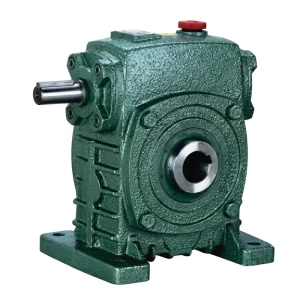
EP-WPKS Single Speed Reducer (4–365 kg)
The EP-WPKS is a flange-mounted single speed gear reducer covering a load range from 4 to 365 kg — the widest weight capacity in the WP single speed series. Its flange-output configuration suits mooring winch drum arrangements where the reducer mounts directly to the drum shaft or to a secondary reduction stage in a two-stage winch gearbox package. The compact envelope keeps the overall winch assembly within the topside footprint constraints that offshore structural engineers apply to skid weight and dimensional envelopes.
Reduction ratios from 1:10 to 1:60 allow the drive system to be tuned to the line pull speed and holding load requirements of each mooring winch application — from lightweight anchor-handling assists on jackup rigs to heavy-duty mooring winches on FPSO turret frames. At ratios of 40:1 and above, the self-locking worm mesh prevents drum back-driving when the motor is tripped or shut down, providing passive load holding without a secondary mechanical brake in lower-risk mooring configurations.
- Load range: 4–365 kg — covers light-duty to heavy mooring winch frame sizes
- Flange-output geometry for direct drum shaft mounting on compact winch skids
- Self-locking at ratios above 40:1 — passive load holding during motor-off periods
- FKM seal and aluminum housing options for marine splash-zone environments
- ISO standard mounting dimensions — compatible with IEC motor frames used globally
Self-Locking Behavior and Load Holding in Mooring Service
Load holding is the single most safety-critical function of a mooring winch drive train. When a platform is positioned on station and the motor is shut down between adjustment cycles, the mooring tension in the anchor line must be sustained by the mechanical drive train itself — any drift in the winch drum translates directly to a shift in platform position that may violate the exclusion zones around adjacent wellheads, risers, or subsea infrastructure.
A single speed reducer based on worm gearing provides this load-holding function passively through the self-locking property that emerges at reduction ratios above approximately 35:1 to 40:1. The geometry of the worm mesh at these ratios makes back-driving thermodynamically unfavorable — the friction forces at the worm thread-to-wheel contact are higher than the tangential force that the drum load would need to generate to rotate the worm shaft in reverse. This means the winch drum remains stationary when the motor is de-energized, holding position without requiring a separate holding brake to remain energized.
This passive holding characteristic has been used in offshore and marine winch engineering for decades as a design simplification: it removes one electromechanical device from the drive train, reducing the number of components that require offshore maintenance and spare-parts management. In practice, high-ratio worm gear speed reducers are typically used alongside a secondary safety brake — rated to hold 150% of the maximum working load — as a redundant fail-safe layer required by classification society rules (DNV, Lloyd’s Register, Bureau Veritas, ABS). The worm reducer handles normal operational load holding; the secondary brake engages only on abnormal load events.
Self-locking worm mesh at ratios 40:1+ holds drum stationary without energizing a separate brake — reduces winch drive train complexity.
Worm-to-wheel sliding contact absorbs snap-loading impulses from anchor chain or wire rope — protects motor shaft and couplings from fatigue damage.
Used alongside a secondary brake rated at 150% WLL — satisfies DNV, ABS, BV, and Lloyd’s Register classification requirements for mooring winch safety systems.
High worm gear contact ratio delivers steady output torque at the drum — prevents stick-slip that would otherwise cause jerky chain or wire rope movement during slow haul-in.

Winch Drive Selection Parameters
Selecting a single speed gear reducer for an offshore mooring winch requires specifying parameters beyond basic input power. The table below outlines the principal selection criteria relevant to marine and offshore winch drive engineering — applicable to jackup rigs, semi-submersibles, FPSO vessels, and fixed platform mooring systems in the North Sea, Gulf of Mexico, Southeast Asian waters, and West African deepwater blocks.
| パラメータ | Typical Range (WP Series) | Notes for Offshore Winch Selection |
|---|---|---|
| 減速比 | 1:10 to 1:60 (single stage) | Ratios 40:1 and above provide passive self-locking; ratios below 35:1 require a separate holding brake in mooring service |
| Load Rating | 4–365 kg (WPKS range) | Applies to the structural load on the winch skid frame — must be verified against dynamic load amplification factors specified in the winch DNV certification |
| Input Power | 0.12–15 kW (WPDS range) | Covers auxiliary mooring winches, tensioner drive assists, and guidewire winches on offshore structures |
| Oil Capacity | 0.4–5.2 L (WPKZ/WPKDZ) | Extended reservoir essential for unmanned auxiliary winch locations on FPSO turret decks where scheduled access is limited by operational constraints |
| Sealing Rating | IP54 standard; IP65 optional | IP65 mandatory for open-deck and splash-zone winch locations; FKM double-lip seal specified alongside IP65 housing for saltwater spray resistance |
| Operating Temperature | −20°C to +40°C standard | North Sea winter ambient (−15°C to −25°C) requires synthetic PAG lubricant to ensure adequate viscosity on cold start before worm mesh reaches operating temperature |
| ATEX Classification | Non-classified standard; consult for zone requirements | The reducer itself is passive — ATEX certification applies to the motor and electrical components; the reducer housing material and seal type may be specified to minimize ignition risk in Zone 1 areas near wellhead decks |
Global Offshore Application Contexts
Mooring winch drive requirements vary significantly between offshore regions, driven by water depth, environmental loading, and the classification society rules that govern each field’s engineering standards. In the North Sea — covering Norwegian, Danish, Dutch, and UK Continental Shelf operations — mooring winches on semi-submersibles and FPSOs operate in water temperatures that drop below 5°C in winter and encounter significant wave heights that impose dynamic mooring loads well above the mean static tension. The single speed reducer in these conditions must maintain adequate lubricant viscosity on cold start and sustain full load-holding capacity through freeze-thaw cycling of the platform structure around it.
In the Gulf of Mexico, jackup rigs and semi-submersibles require mooring winches that can handle the rapid repositioning cycles that well-to-well moves demand, as well as the high dynamic loads generated by hurricane-season wave spectra. The worm gear speed reducer’s shock-damping characteristic — the result of its sliding contact geometry — is particularly valuable in these conditions, absorbing the snap-loading pulses that occur when a taut mooring line is struck by a large wave crest.
Southeast Asian offshore fields — including the Malacca Strait area, the South China Sea, and the Timor Sea — operate in warmer ambient conditions that benefit from the synthetic PAG lubricant options available for WP-series single speed reducers, reducing operating temperature in the worm mesh and extending the drain intervals that are particularly valuable on remote unmanned wellhead platforms. Procurement teams in these regions consistently select a single speed reducer from the WP-series flange-output range for its combination of compact footprint and passive load-holding capability. West African deepwater operations off Angola and Nigeria specify the full marine material package — aluminum housing, stainless shaft, FKM seals, epoxy coating, and A4 fasteners — to resist the combination of salt-laden tropical humidity and process chemical exposure on topsides structures where mooring winch locations are close to flare booms or chemical injection headers. In each of these regions, the single speed reducer’s self-locking characteristic and worm mesh damping have made it the preferred drive element for auxiliary mooring winch and tensioner drive applications across the past several decades of offshore field development.

Installation, Alignment, and Offshore Commissioning
Installing a single speed gear reducer into a mooring winch skid on an offshore platform introduces constraints that onshore installation does not: working space is typically confined to the winch skid envelope, lifting is subject to platform crane capacity and lift rigging weight limits, and commissioning must be completed within the platform’s scheduled maintenance window rather than at the convenience of the maintenance crew.
Shaft alignment between the motor, reducer, and drum shaft on a mooring winch skid should be performed using laser alignment equipment rather than dial gauges, given the access restrictions that typically prevent mounting a dial indicator base on one side of a marine coupling. Acceptable parallel and angular misalignment tolerances for flexible jaw couplings commonly used on winch drives range from 0.1 to 0.3 mm parallel offset and 0.5° to 1.0° angular, but always deferred to the specific coupling manufacturer’s published limits rather than general rule-of-thumb figures.
Oil fill quantity must be adjusted for the installed orientation. A WP-series single speed reducer mounted with the motor above and the output shaft pointing downward — common in vertical-drum mooring winch arrangements — requires a different fill volume than the same unit mounted horizontally. The lubrication chart specific to the selected single speed reducer frame size and mounting orientation provides the correct fill level reference. Commissioning checks should include a no-load rotation test of at least 30 minutes to verify bearing temperature rise, oil temperature, and seal integrity before the winch is loaded against the mooring line. A commissioning record documenting these checks provides the maintenance baseline from which future single speed reducer condition assessments are measured throughout the platform’s service life.
Related Products for Offshore Winch Drive Systems
A complete offshore mooring winch drive system requires more than the reducer unit. The products below are regularly sourced alongside the single speed reducer to form a dimensionally matched, one-supplier drive package — reducing offshore procurement lead time and simplifying the technical documentation that classification society review requires for certified winch assemblies.


私たちについて
The manufacturing portfolio spans agricultural gearboxes, worm gear reducers, planetary gear drives, power take-off shafts, hydraulic cylinders, gears, chains, and motors — all produced within an ISO 9001:2015 certified facility. The engineering scope covers both catalog-standard products and application-specific configurations designed to customer duty requirements, including offshore and marine specifications with enhanced corrosion protection and specialist seal materials.
Design and production capability extends across housing materials including ductile iron, cast iron, cast steel, precision cast steel, and cast aluminum. Component-level manufacturing covers precision-cut gears, roller chain sprockets, worm wheels, worm shafts, pulleys, and an extensive portfolio of standard and non-standard mechanical parts for global OEM and project engineering clients. Offshore and marine procurement teams can consolidate reducer, motor, and associated mechanical components under a single technical supplier relationship, simplifying documentation packages for classification society review and reducing the number of vendor audits required during project qualification phases.
ワークショップ



よくある質問
編集者: PXY