
Packaging & Logistics · Conveyor Drive Systems
A technical reference for packaging line engineers, plant maintenance teams, and machine builders across North America, Europe, and the Asia-Pacific region who are specifying or replacing conveyor drive components in case erecting and case sealing applications.
The Role of Speed Reduction in End-of-Line Packaging Equipment
End-of-line packaging machinery — case erectors that form flat corrugated blanks into open boxes, and case sealers that close and tape finished cases — operates under conditions that place specific, repeatable demands on the conveyor drive system. Each machine must move cases at a controlled, stable speed that matches the upstream filling line throughput. Too slow and cases queue up, disrupting the filling operation; too fast and the sealing tape fails to adhere or folded case flaps spring open before the tape reaches them.
A single speed reducer installed between the drive motor and the conveyor belt or chain is the most straightforward way to achieve this controlled output speed. The worm gear speed reducer brings the AC motor’s synchronous speed — typically 1450 rpm on 50 Hz supply or 1740 rpm on 60 Hz — down to the 15–80 rpm range that drives conveyor shafts, forming rollers, and compression belts in these applications. The right reducer selection ensures smooth, continuous torque delivery that protects both the conveyor structure and the cases being processed.

製造構造
The WP series single speed reducer is built around an integral one-piece cast-iron housing that contains and aligns the complete worm-and-wheel assembly. This monolithic structure is machined in a single setup on a CNC machining center, which establishes the center distance between the worm shaft and the worm wheel shaft with the tight dimensional tolerance required for efficient, quiet gear mesh. In packaging environments where machine noise directly affects the working conditions of operators stationed near the line, this precision geometry contributes to the characteristically low-noise operation that worm gearing provides.
The worm shaft is supported by tapered roller bearings or deep-groove ball bearings at both ends of the housing, depending on the frame size. This dual-bearing arrangement handles both radial loads from belt tension and axial thrust that develops from the helical engagement geometry of the worm-and-wheel pair. On packaging conveyors where belt tension is adjusted seasonally or after belt replacement, the ability of the reducer bearings to absorb variable radial loads without shaft deflection is a key durability factor.
Input shaft configurations vary across the WP series to suit different motor mounting arrangements. Flange-input models (WPKA, WPDKA) accept IEC-standard motor flanges directly on the reducer input face, producing a compact motorized reducer package that mounts cleanly in the confined drive compartments of modern case erector frames. Foot-mounted variants (WPDS, WPKS) suit drive configurations where the motor and reducer are mounted on a common sub-plate with a flexible coupling or belt drive between them, a common arrangement in retrofitted packaging lines where the original motor mounting position must be retained.
材料システム
Housing castings in the WP series are produced from gray cast iron or ductile iron. Gray iron provides excellent vibration damping characteristics that reduce transmitted vibration into the packaging machine frame — an advantage in case sealers where vibration can disturb the case during the taping cycle and cause misaligned or wrinkled tape seals. Ductile iron is specified for larger frame sizes and higher-torque models where impact resistance and tensile strength are the governing criteria.
The worm itself is manufactured from case-hardened alloy steel, typically 20CrMnTi grade, with the tooth form ground after heat treatment to achieve the surface finish and profile accuracy required for smooth sliding contact with the worm wheel. Ground worm geometry produces less friction heat per unit of transmitted power compared to milled or hobbed worms, which is relevant in packaging lines that run three-shift continuous operation where reducer housing surface temperatures must be managed.
Worm wheels are cast from tin bronze or phosphor bronze, materials selected for their controlled wear characteristics against the hardened steel worm. In food and beverage packaging facilities where incidental contact with the machine exterior by cleaning chemicals is possible, the bronze wheel material is inherently resistant to the alkaline detergents used in washdown procedures — unlike sintered or plastic alternatives. The output shaft and input shaft are machined from medium-carbon steel, with keyway seats and tolerance zones sized to fit standard coupling bores and sprocket hubs found on packaging machinery.
Recommended Model for Packaging Line Conveyor Drives
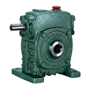
EP-WPKS — 4 to 365 kg Single Speed Reducer
The EP-WPKS is a flange-mounted, foot-base single stage speed reducer with a keyway output shaft arrangement that is directly applicable to conveyor drive shafts in case erector and case sealer lines. The input flange accepts a motor directly on the reducer face, and the output shaft connects to the conveyor drive roller via a chain sprocket or coupling hub. The unit weight range of 4 to 365 kg covers the full span of frame sizes from compact low-power units used in light-duty carton conveyor sections through heavy frames suited to palletizer infeed conveyors handling dense case loads.
| パラメータ | 価値 |
|---|---|
| Unit Weight Range | 4~365kg |
| Input Connection | IEC motor flange (direct mount) |
| Reduction Ratio (Single Stage) | 1:10 – 1:60 |
| 入力電力 | 0.12 – 33 kW |
| ハウジング材 | Cast iron (integral box) |
| Frame Sizes (center distance) | 40 – 250 mm |
| Operating Ambient Temp. | -40°C to +40°C |
How the Drive System Works in Case Forming and Sealing Equipment
In a case erector, the conveyor drive performs two distinct functions. First, it drives the indexing mechanism that positions flat case blanks from the magazine to the forming station. Second, it powers the outfeed conveyor that transports erected cases to the filling station at a speed synchronized with the downstream process. Both functions require a stable, repeatable output speed — variation in conveyor speed causes misalignment between the erected case and the filling station nozzles or mechanical guides, resulting in damage to cases or product spills.
In a case sealer, the conveyor drive moves the filled, open case through the compression section where the top flaps are folded and the sealing tape is applied. The speed of this conveyor directly determines the dwell time under the folding rails and the tape head — too fast and the tape stretches or misapplies; too slow and the throughput rate drops below the line target. A single reduction worm reducer paired with a fixed-speed or VFD-controlled motor gives packaging engineers the precise output speed control to optimize this dwell time for each case size and tape specification.
The self-locking tendency of worm gearing at higher reduction ratios — typically ratios above 1:30 — provides an inherent hold function when the motor is de-energized. In a case sealer where cases queue up against a stopped compression section, this prevents the conveyor from being back-driven by the weight of accumulated cases on a slight incline, avoiding case pile-ups that can damage both the machine and the product.

Speed and Ratio Selection for Packaging Conveyor Applications
The table below maps common packaging machine conveyor functions to typical output shaft speeds and the corresponding single stage reduction ratio needed to achieve them from a standard 4-pole motor. These are representative values; actual selection must be verified against the conveyor roller diameter, chain pitch, and case throughput rate specified by the machine builder.
| Conveyor Function | 出力回転数(rpm) | Motor Input (rpm) | 比率範囲 | Preferred Mounting |
|---|---|---|---|---|
| Case erector outfeed conveyor | 25 – 45 | 1450 | 1:30 – 1:60 | Flange or foot |
| Case sealer compression conveyor | 15 – 35 | 1450 | 1:40 – 1:60 | Foot (sub-plate) |
| Accumulation table / buffer conveyor | 10 – 20 | 1450 | 1:60 – 1:80 (double stage) | Foot |
| Palletizer infeed lane conveyor | 40 – 80 | 1450 | 1:15 – 1:30 | Flange or hollow shaft |
| Label applicator feed conveyor | 20 – 50 | 1450 | 1:25 – 1:50 | フランジ |
Alternative for High-Load Palletizer and Case Transfer Drives
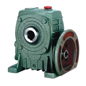
EP-WPDKA — 5 to 350 kg Single Speed Reducer
The EP-WPDKA is a double-output-shaft configuration with a motor flange input, making it suited to conveyor drives that require simultaneous output to both sides of a conveyor frame — for example, a case sealer compression section where both left and right compression belts must be driven at identical speed from a single power source. The flange input eliminates the need for a separate motor coupling, and the double output shaft allows a single reducer to power both conveyor rail drive assemblies with guaranteed speed synchronization.
| パラメータ | 価値 |
|---|---|
| Unit Weight Range | 5~350kg |
| 出力構成 | Double output shaft |
| Input Connection | IEC motor flange (direct mount) |
| 減速比 | 1:10 – 1:60 |
| Frame Sizes | 40 – 250 mm center distance |
Lubrication and Oil Capacity Considerations for Packaging Environments
Packaging facilities — particularly those handling food, beverage, pharmaceutical, and personal care products — maintain stricter standards for lubricant management than general industrial sites. The worm speed reducer installed in these lines must be filled with the correct lubricant grade and oil volume from commissioning. The EP-WPZ and EP-WPKZ models carry oil capacities from 0.4 L to 5.2 L depending on frame size, a volume range that accommodates both the smallest conveyor drive reducers and the heaviest palletizer drives.
In facilities with incidental food contact risk near the conveyor drive, food-grade H1-rated synthetic gear oils are available and compatible with the lip seal and gasket materials in WP series units. The seal specification should be confirmed with the lubricant supplier before filling, as some food-grade polyalkylene glycol (PAG) bases require fluoroelastomer (FKM) lip seals rather than standard NBR seals to achieve acceptable service life.
Oil changes at 300–500 hours initial service and every 3,000–5,000 hours in continuous operation represent a practical maintenance schedule for packaging line reducers. Packaging facilities typically schedule quarterly or bi-annual planned maintenance shutdowns — aligning the reducer oil change with one of these shutdowns avoids unplanned downtime from lubricant degradation-related bearing or worm wheel damage.

Practical Selection Criteria for Packaging Line Engineers
Required Output Torque
Calculate from the total conveyor load (case weight plus belt tension), the drive roller radius, and the friction coefficients of the conveyor belt or chain on the support structure. Apply a service factor of 1.25 for smooth operation, or 1.5 if the conveyor starts under full load or experiences periodic shock loading from case feeding.
減速比
Determine the required output speed from the conveyor belt speed specification and the drive roller circumference. Divide motor synchronous speed by the required output rpm to find the nominal ratio, then match to the nearest catalogue ratio in the WP series (available from 1:10 to 1:60 in a single reduction stage).
Mounting Geometry
Confirm the orientation of the input and output shafts relative to the machine frame before specifying the model suffix. In case sealers, the output shaft is commonly horizontal; in vertical-lift conveyor sections, a vertical output configuration may be needed. Specifying the wrong orientation requires a motor or shaft repositioning that adds significant cost to the installation.
VFD or Fixed Speed
Lines handling multiple case sizes often use a VFD on the drive motor to adjust conveyor speed between changeovers. Confirm that the motor is rated for inverter duty and that the reducer’s rated output torque covers the full torque demand across the intended speed range, including at low-frequency operation where motor cooling efficiency is reduced.
侵入保護
Packaging lines in the food and beverage industry undergo regular washdown with pressurized water and detergent. For direct-washdown zones, specify reducers with reinforced lip seals and confirm housing vent plug positioning so that steam or water ingress through the vent path is avoided. Standard WP series sealing is suitable for splashing and spray; pressurized washdown exposure requires additional seal specification.
Thermal Loading
Packaging facilities in warmer climates — including distribution centers in South and Southeast Asia, the Middle East, and equatorial Africa — can have ambient temperatures above 35°C, which reduces the thermal margin of the reducer. In these conditions, select a slightly larger frame or specify a synthetic gear oil with a higher viscosity index to maintain adequate oil film at elevated sump temperature.
Efficiency, Noise, and Reliability in High-Speed Packaging Operations
High-speed packaging operations in Europe, North America, and Australia increasingly benchmark their end-of-line equipment against overall equipment effectiveness (OEE) targets, and unplanned conveyor drive failures are one of the most common contributors to unscheduled downtime in these operations. A correctly selected single speed reducer running within its rated torque and thermal envelope is not typically the weakest link in a packaging line — the weak points are usually lubricant neglect, incorrect installation, or operating the unit at ratios or ambient temperatures outside the specification envelope.
Worm gear reducers operate at mechanical efficiencies of 70%–88% depending on ratio and speed, lower than helical gear reducers of equivalent size. For packaging line engineers focused on energy cost reduction, this efficiency gap is real but often modest in absolute power terms — a 1.5 kW conveyor drive operating at 80% efficiency consumes 1.875 kW at the motor terminals, which at typical industrial electricity tariffs represents a manageable additional operating cost that is frequently offset by the worm’s simpler maintenance requirements, inherent self-locking at high ratios, and compact right-angle geometry that simplifies machine layout. Where energy consumption is a primary concern, pairing the single speed worm gear reducer with a premium-efficiency IE3 motor recovers much of the efficiency gap at the system level.
互換性のあるドライブシステムコンポーネント
The single speed reducer works as part of a broader drive system. The following components are manufactured to compatible standards and are available from the same source for integrated procurement:

電気モーター
IEC-frame AC motors in B3, B5, and B14 configurations are available to pair directly with WP series flange-input reducers. Motor selection covers 50 Hz and 60 Hz supply frequencies and standard 2-pole and 4-pole arrangements, matching the base input speed to the target conveyor output speed through the selected worm gear reduction ratio. Inverter-duty windings are available for VFD-controlled packaging lines.

ウォームギアボックス
Where a packaging application calls for a reduction ratio beyond the single stage range — accumulation conveyors requiring output speeds below 20 rpm, or multi-stage drive systems with split reduction — the full worm gearbox series provides universal, double-stage, and multi-stage configurations. Shared housing casting standards ensure that spare parts and seal kits are interchangeable across model variants, simplifying maintenance inventory for facilities running multiple conveyor drive types.
メーカーについて
The facility operates under ISO 9001:2015 certification and integrates the complete production chain from casting through precision machining, heat treatment, and assembly under one roof. The manufacturing range spans agricultural gearboxes, worm gear reducers, planetary gear drives, power take-off shafts, hydraulic cylinders, gears, sprockets, chains, and motors — a portfolio breadth that allows packaging OEMs and end-users to consolidate their drivetrain component sourcing with a single qualified supplier.
Casting materials cover ductile iron, gray cast iron, cast steel, precision cast steel, and cast aluminum, allowing the optimal material to be matched to the structural and weight requirements of each application. Non-standard configurations — modified shaft lengths, special bore diameters, non-catalogue ratios, custom flange patterns — are developed alongside the standard range. Worm gears, sprockets, pulleys, worms, and shafts produced in-house ensure that all mating components meet the dimensional tolerances required for first-fit installation without on-site modification.
よくある質問
編集者: PXY