
Cooling Systems · Drive Technology
A technical guide covering worm gear reducer construction, material engineering, fan load characteristics, and product selection for cooling tower drive retrofit and new-installation programmes worldwide.
Cooling towers are among the most continuously operated mechanical systems in industrial facilities — power stations, petrochemical complexes, data centres, HVAC installations, and food-processing plants all rely on cooling tower fans running for thousands of hours per year. The drive system between the motor and the fan determines not only energy efficiency but the operational reliability of the entire cooling circuit. When an existing drive arrangement — whether a direct belt drive, a worn gear drive, or an obsolete multi-stage gearbox — reaches the end of its service life, the replacement choice is consequential. A single speed reducer based on single stage worm gear technology has become an increasingly common upgrade selection, particularly for small to medium fan cell applications where the right-angle drive geometry, compact footprint, and competitive total cost of ownership make it a practical fit.
This article examines what makes a single speed reducer suitable for cooling tower fan service, covering the mechanical construction, material system, lubrication requirements, and rated performance characteristics that matter most in this application. Two product configurations from the WP series are highlighted, with specifications drawn from the catalogue. Selection guidance and a comparison table assist engineers planning either a direct replacement or a drive upgrade that changes the motor mounting arrangement.
Cooling tower fan drive applications appear in facilities across North America, Southeast Asia, the Middle East, and Europe, each presenting different ambient temperature conditions, humidity levels, and maintenance access constraints. The selection guidance in this article accounts for those geographic variations where they influence product choice.

Why a Single Speed Reducer Is Selected for Cooling Tower Fan Drive Upgrades
Cooling tower fans operate at relatively low rotational speeds — typically 50 to 200 RPM for larger fiberglass or aluminium fan assemblies — while being driven by standard AC induction motors running at 960, 1450, or 1500 RPM depending on pole count and supply frequency. Bridging that speed gap requires a gear reduction stage, and the single stage right-angle worm-gear speed reducer delivers ratios from 10:1 through 60:1 in a single gear mesh, covering virtually the entire speed range demanded by cooling tower fan practice. Multi-stage inline gearboxes could achieve the same reduction, but at greater axial length and higher mechanical complexity — neither of which favours the confined structural bays of a cooling tower cell where the drive must sit above the fan deck.
The right-angle geometry of the worm speed reducer is directly compatible with the standard cooling tower drive arrangement, where the motor sits horizontally on a lateral motor plate while the fan shaft is vertical. A single stage worm gear reducer connects both axes cleanly within a compact cast housing, without bevel gear pre-stages or adapter flanges. For upgrade projects where the existing motor is retained and only the gearhead is replaced, this geometric compatibility frequently allows a direct mechanical fit to the existing motor plate and fan shaft without structural modification of the tower cell.
For facilities managing several dozen cooling tower cells — as is common in large petrochemical complexes in the Gulf region or refinery clusters across North America — the simplicity of the single speed reducer’s maintenance regime is also a procurement and operations argument. One gear mesh, one oil sump, one set of seals: the spare-parts inventory is straightforward, and technician training requirements are minimal compared to multi-stage alternatives. These operational economics consistently support the worm gear speed reducer as the upgrade drive of choice for facilities with limited on-site maintenance resources.
Manufacturing Structure of the WP-Series Single Speed Reducer
The WP-series single speed reducer is built around an integrally cast one-piece housing that encloses the worm shaft and output shaft in a right-angle arrangement. Casting the housing as a single component rather than assembling it from two bolted halves means that the bearing bores for both shafts are machined in a single fixturing operation, ensuring bore-to-bore perpendicularity and concentricity that a split-housing design cannot match without careful reassembly alignment. In cooling tower service, where the drive is typically mounted on a fan deck exposed to vibration from both fan unbalance and wind loading, the dimensional stability of an integral casting maintains bearing alignment over the years-long service intervals between planned maintenance shutdowns.
The worm shaft is supported at both ends by rolling element bearings in a straddle configuration, distributing shaft bending loads symmetrically and reducing peak bearing load compared to a cantilevered arrangement. This structural layout is important in cooling tower applications because the fan shaft imposes a moment load on the output shaft of the reducer — from the fan weight and from aerodynamic side thrust — which is transmitted through the output shaft bearings into the housing. The straddle-mounted worm shaft absorbs the reaction to this load without concentrating stress at a single bearing location.
Center-distance options across the WP series range from 40 mm to 250 mm, with standard frame sizes at 40, 50, 60, 70, 80, 100, 120, 135, 155, 175, 200, and 250 mm. This range of center distances corresponds to a range of output torque and shaft size that covers fan cell drive requirements from small packaged HVAC cooling towers through to large industrial cell drives. The housing exterior provides machined flat surfaces at all four potential foot positions, allowing the same casting to be mounted in multiple orientations by installing feet at the appropriate pair of surfaces.
Material System: Housing, Worm, Wheel, and Shaft Composition
The housing is cast in grey cast iron, a material selected for its strength-to-weight balance, vibration damping capacity, and proven durability in outdoor industrial environments. Grey cast iron’s damping coefficient is significantly higher than that of steel or aluminium, which means the housing absorbs a proportion of the cyclic vibration generated by fan blade passage — typically at frequencies of 3 to 10 Hz for large industrial fans — rather than transmitting it entirely to the mounting structure. Over a multi-year service period in a cooling tower, this damping characteristic reduces fatigue loading on the fan deck and mounting bolts.
The worm shaft is produced from alloy steel and subjected to case-hardening to achieve a tooth-flank surface hardness of 45–55 HRC. After hardening, the tooth profile is precision-ground, removing the dimensional distortion introduced by the heat treatment cycle and producing a smooth, accurate contact surface. Ground worm flanks run cooler than hobbed-only surfaces under equivalent load because they generate less sliding friction, which directly benefits cooling tower applications where heat dissipation from the reducer is limited — particularly in enclosed fan deck structures in hot climates where the ambient temperature around the drive reaches 45°C or more.
The worm wheel is cast from phosphor bronze or tin bronze. The dissimilar-metal pairing of hardened steel worm against bronze wheel is the cornerstone of worm drive tribology: the bronze retains lubricant film effectively at the contact and wears preferentially, protecting the steel worm from scoring damage during the occasional momentary loss of full hydrodynamic lubrication that occurs at startup from rest. Output and input shafts are medium-carbon or alloy steel, dimensioned for the rated torque at each frame size and machined with keyways or spline profiles that match standard shaft coupling bores for straightforward integration with fan shaft couplings and motor flexible-disc couplings.
Featured Product: EP-WPKZ Single Speed Reducer — 0.4 to 5.2 L Oil Capacity, Hollow-Shaft Configuration
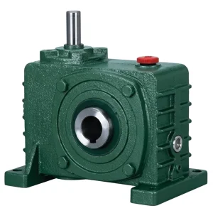
The EP-WPKZ combines the hollow-shaft shaft-mount configuration of the WPKA series with the extended oil reservoir of the WPZ series — an oil capacity range of 0.4 to 5.2 litres depending on frame size. For cooling tower fan drives, the extended reservoir provides a larger thermal buffer during continuous operation, reducing the rate of oil temperature rise during peak summer ambient conditions. The hollow output bore mounts directly over the fan shaft, eliminating the solid-shaft coupling that would otherwise be required and removing the alignment procedure that solid-shaft installations demand. A torque arm anchored to the fan deck bracket resists the reaction torque from the worm mesh, completing the installation without foot-mounting bolts or motor plate modification.
The WPKZ is particularly well-suited to upgrade projects where an existing belt drive or multi-stage gearhead is being replaced. The shaft-mount engagement to the existing fan shaft preserves the fan’s mechanical interface, and the motor flange accepts standard IEC or NEMA motors, meaning the existing motor can often be reused without modification if its speed and power ratings align with the required output conditions at the chosen reduction ratio.
| Parameter | Specificatie |
|---|---|
| Oil Capacity Range | 0.4 – 5.2 litres (model-dependent) |
| Output Configuration | Hollow bore, shaft-mount with torque arm |
| Reduction Ratios Available | 10:1 / 15:1 / 20:1 / 25:1 / 30:1 / 40:1 / 50:1 / 60:1 |
| Behuizingsmateriaal | Grey cast iron with damping properties |
| Worm Wheel Material | Phosphor bronze / tin bronze |
| Worm Shaft Material | Case-hardened alloy steel, ground tooth flanks |
| Center Distance Frame Sizes | 40 – 250 mm (12 standard frame sizes) |
| Typical Application | Cooling tower fan drive, continuous-duty low-speed fan |
| Gear Step | Single stage (single reduction) |
| Input Hardness | Hardened tooth surface (45–55 HRC) |
Fan Load Characteristics and Their Effect on Reducer Selection
Cooling tower fans present a centrifugal load profile: torque requirement varies with approximately the square of shaft speed, and power varies with the cube. At the low output speeds produced by the single speed reducer — typically 30 to 150 RPM for cooling tower service — this load curve means that the peak mechanical stress on the reducer occurs at full-speed steady-state operation rather than during acceleration from rest, which differs from many other drive applications where starting torque governs selection. For the single stage right-angle worm-gear speed reducer, this profile favours selection based on continuous thermal power capacity at the operating point rather than peak torque rating.
Fan starting, however, still deserves attention. Large-diameter cooling tower fans carry significant rotational inertia, and the current drawn during motor start produces an initial torque pulse through the reducer that can reach 1.5 to 2.5 times the full-load torque depending on motor start configuration. Across-the-line direct-on-line starting is the most demanding scenario; soft-starter or variable frequency drive assisted starting reduces the starting torque pulse and is increasingly common in facilities seeking to reduce mechanical stress on drive components and extend service intervals. When a VFD is specified on the drive, the thermal considerations for the worm gear reducer at low speed partial load should be reviewed, since at very low fan speeds the reduced heat dissipation from oil circulation within the sump may require additional consideration during long periods of low-speed running.
Wind loading on exposed cooling tower cells adds a dynamic component to the fan shaft load that is absent from sheltered drive applications. In coastal facilities in the Gulf of Mexico, coastal Australia, or typhoon-prone regions of East Asia, occasional high-wind events impose lateral bending moments on the fan shaft that transfer to the output shaft of the reducer. The output shaft bearing load rating must accommodate these wind loads in addition to the normal fan weight and aerodynamic thrust. For exposed locations, specifying a frame size with output shaft bearing capacity meaningfully above the calculated running load provides a margin that absorbs peak wind events without causing bearing distress.

Lubrication System and Thermal Management in Continuous Fan Drive Duty
Cooling tower fan drives are among the highest-duty-cycle applications that worm gear speed reducers encounter. Unlike process plant drives that may cycle intermittently, a cooling tower fan in a process facility or power station runs essentially continuously for weeks or months between planned shutdowns. This continuous operation makes the oil system the central maintenance focus. The extended oil reservoir in EP-WPZ and EP-WPKZ models — 0.4 to 5.2 litres depending on frame size — provides thermal capacity that buffers the sump temperature against rapid rise during high-ambient periods, such as the summer peak loads experienced in Middle Eastern petrochemical facilities or Southeast Asian industrial parks where air temperatures regularly exceed 40°C.
Oil grade selection for continuous fan drive service follows the same principles as other worm gear applications: a VG220 or VG320 mineral gear oil at temperate ambient conditions (5–35°C), transitioning to a synthetic polyalphaolefin oil at the same ISO VG grade for facilities in hot or cold climate extremes. Cooling tower environments add one complication: the high-humidity air adjacent to the tower fill promotes condensation on the exterior of the reducer housing and can slowly migrate past shaft seals if the seal condition is allowed to deteriorate. Water contamination of the gear oil appears as milky discoloration and reduces lubricant film strength, accelerating bronze wheel wear. The EP-WPKZ’s extended oil capacity means that a minor water ingress event dilutes in a larger volume — reducing the concentration of contamination — compared to a small-sump unit, but it does not eliminate the need for periodic oil sampling or visual inspection.
First oil change at 200–500 hours of operation removes run-in wear particles and any manufacturing residues from the new unit. After the initial change, the recommended interval for mineral oil is 2,000–4,000 hours or annually, whichever comes first. For continuously running cooling tower fans, the annual interval is often the governing criterion rather than the hour count. Facilities in tropical climates with year-round high temperatures and humidity should err toward the shorter 2,000-hour interval and consider synthetic oil for its extended service life and better water-shedding characteristics.
WP Series Single Speed Reducer Variants: Cooling Tower Fan Drive Fit
The table below compares four WP-series configurations against the key requirements of cooling tower fan drive upgrades, to support specification and procurement decisions.
| Serie | Uitvoertype | Oil Capacity | Ratios | Best-Fit Scenario |
|---|---|---|---|---|
| EP-WPKZ | Hollow bore, shaft-mount | 0.4 – 5.2 L | 10:1 – 60:1 | Direct fan-shaft upgrade, continuous duty, hot climate |
| EP-WPZ | Solid output shaft, foot-mount | 0.4 – 5.2 L | 10:1 – 60:1 | New installation with coupling to fan shaft, extended thermal reserve |
| EP-WPKA | Hollow bore, standard oil | Standard sump | 10:1 – 60:1 | Intermittent fan duty, moderate ambient, smaller cell drives |
| EP-WPDS | Solid shaft + motor flange | Standard sump | 10:1 – 60:1 | HVAC cooling tower, motor-integrated compact unit |
Planning a Cooling Tower Fan Drive Upgrade: Key Engineering Steps
A structured upgrade sequence reduces the risk of specification errors and installation delays. The following steps apply whether the project involves a single cell or a multi-cell programme across an industrial facility.
Step 1 — Fan Speed and Torque Survey
Measure or confirm the existing fan shaft speed in RPM and the drive torque at full load. For replacement projects, this data is obtained from the existing drive documentation or by measurement. For new installations, the fan manufacturer’s data sheet provides design point speed and shaft power.
Step 2 — Ratio and Frame Size
Divide the motor synchronous speed by the required fan shaft speed to determine the target reduction ratio. Select the closest standard ratio (10:1 through 60:1) and confirm that the output torque at that ratio from the chosen frame size meets the fan shaft torque requirement with an appropriate service factor of at least 1.25 for normal continuous duty.
Step 3 — Thermal Verification
Confirm that the continuous thermal power rating of the selected frame size equals or exceeds the running input power at the expected ambient temperature. For hot-climate sites above 35°C ambient, apply the manufacturer’s derating factor and consider specifying the EP-WPKZ with its extended oil reservoir to improve thermal reserve without moving to the next frame size.
Step 4 — Mounting and Access
Confirm the output shaft bore diameter and keyway for the WPKZ shaft-mount variant matches the fan shaft. Verify that the torque arm mounting point on the fan deck bracket is available or can be added without structural modification. Check that oil fill, drain, and level plugs are accessible from the fan deck service platform in the installed orientation.

Noise, Corrosion, and Environmental Exposure in Cooling Tower Installations
Cooling towers present a harsher external environment for drive components than most indoor industrial applications. The combination of airborne water droplets from the drift eliminators, warm humid air rising through the fill media, and — in process cooling tower service — potential contamination of the cooling water circuit with process chemicals creates an environment that demands attention to the reducer’s external protection system. The standard enamel finish over grey cast iron provides adequate protection for clean water service cooling towers, but facilities where the cooling water is chemically treated or where the tower is located in an industrial area with atmospheric acid or chloride contamination should specify an epoxy powder coat or two-part epoxy paint system over a zinc phosphate primer.
Shaft seal integrity is the most critical protection point on a cooling tower drive reducer. The output shaft passes through the housing at the point closest to the cooling air stream, and if the shaft seal deteriorates — through wear, age, or shaft runout from a worn fan hub — the humid air and water mist enter the sump directly. Routine seal inspection at every oil change, combined with monitoring of oil colour and condition, provides the earliest warning of seal degradation before significant damage to the worm wheel or bearings occurs. Lip seals should be replaced at the first sign of weeping at the shaft exit, well before visible water ingress is apparent.
Acoustically, the worm gear speed reducer contributes less to overall cooling tower noise than the fan itself, the air entry noise at the inlet louvres, and the water splash in the basin. The sliding contact mechanism of worm mesh geometry produces a smooth, broadband noise signature without the discrete tonal frequencies that helical gears generate at their mesh frequency and harmonics. For noise-sensitive sites — cooling towers adjacent to residential areas in European industrial parks or near hospitals in urban locations — the worm drive’s relatively benign acoustic profile is an advantage that multi-stage helical alternatives do not offer.
Compatible Drive System Components
A complete cooling tower fan drive requires matched motor and gearhead components. Both product categories below are available from the same manufacturing source, enabling unified supply that simplifies procurement, documentation, and after-sales service across multi-cell upgrade programmes.

Three-phase motors in IEC and NEMA frame sizes, rated for fan duty with Class F insulation and IP55 enclosure suitable for the humid cooling tower environment. Sourcing the motor and single speed reducer from one supplier ensures that the motor flange dimensions and shaft profile match the WPDS or WPKZ motor-flange interface without requiring additional adapter components, which shortens installation time on the fan deck and reduces the total number of mechanical interfaces in the drive assembly.

Wormwieloverbrenging met volledig bereik
Where very large cooling tower cells require output torques that exceed the WP single-stage range at the standard frame sizes — or where reduction ratios above 60:1 are needed for very large slow-speed fans — the extended worm gearbox programme includes compound two-stage units and NMRV compact series that maintain the same material and lubrication standards as the WP single speed series. A single-supplier worm gearbox selection across different cell sizes in the same facility simplifies the spare parts programme and enables standardised maintenance procedures.
Over de fabrikant
The production facility behind these products holds ISO 9001:2015 certification and maintains an extensive manufacturing scope covering agricultural gearboxes, worm gear reducers, planetary gear drives, power take-off shafts, hydraulic cylinders, gears, chains, and electric motors. Engineering and production capabilities span a wide range of gearbox and assembly types across materials including ductile iron, cast iron, cast steel, precision cast steel, and cast aluminum, complemented by in-house production of gears, sprockets, worm gears, pulleys, worms, and shafts in both standard catalogue and application-specific configurations. OEM development programmes for cooling tower equipment builders and HVAC system integrators are supported through direct technical engagement from the engineering team.
Workshop




Veelgestelde vragen
Redacteur: PXY