
Construction & Material Handling · Technical Guide
A technical reference for crane engineers, construction equipment OEMs, and site maintenance teams specifying worm gear single speed reducers for tower crane slewing ring drive mechanisms in high-rise construction projects across the United Arab Emirates, Australia, Germany, Canada, the United Kingdom, and Singapore.
The slewing ring of a tower crane is the bearing and gear assembly that allows the crane’s upper structure — jib, counter-jib, hoist trolley, and load — to rotate around the mast. The drive mechanism that powers this rotation is one of the most mechanically demanding applications that a enkel hastighetsreducerare is asked to serve in the construction equipment sector. It must start and stop smoothly under load, reverse direction hundreds of times per shift, resist the overturning moments generated when a loaded jib swings in wind, and operate continuously for months at a time on a high-rise construction site without shutdown for drive train service. Specifying the wrong snäckväxelreducerare for a slewing drive results in either premature failure — an unacceptable outcome given the height and safety implications — or excessive conservatism that adds unnecessary weight and cost to a crane design where both are constrained by structural and transport limits.
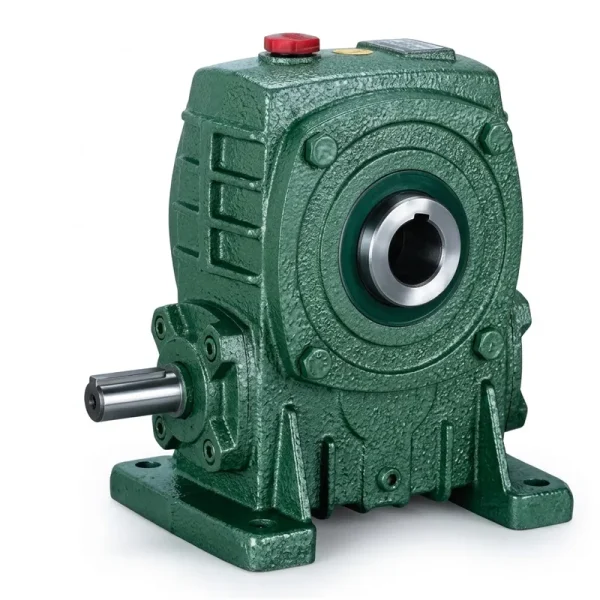
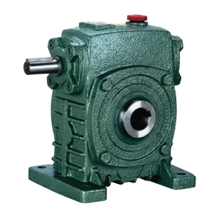
This article covers the mechanical demands of a tower crane slewing ring drive, the manufacturing structure and material selection criteria for a single stage speed reducer suitable for this application, the lubrication and environmental considerations specific to elevated construction site installation, and the EP-WPKA and EP-WPKS series products as reference designs for the small-to-medium and medium-to-large ends of the tower crane slewing drive market.
Load Characteristics of a Tower Crane Slewing Drive
A tower crane slewing drive imposes a load profile that combines three distinct force components simultaneously. The first is the slewing torque: the force needed to accelerate or decelerate the rotating superstructure mass (which may reach 15,000–80,000 kg including the jib, counter-jib, hoist machinery, and suspended load) through its angular range. For a typical flat-top tower crane with a 50 m jib radius carrying a 3-tonne load, the slewing motor torque during constant angular velocity rotation is relatively modest — perhaps 10–20% of the rated motor torque. The demanding condition is deceleration: braking the rotating superstructure smoothly against its angular momentum without imposing load oscillation on the suspended load requires precise torque control through the reducer at the transition from motoring to braking.
The second component is wind load: a loaded jib exposed to a 10 m/s wind generates a lateral force that creates a tangential moment on the slewing ring, opposing or assisting rotation depending on wind direction relative to the jib. During a wind gust, this moment can reverse abruptly, demanding that the enkel hastighetsreducerare carry a torque reversal without backlash-induced jerk — the same tooth back-face engagement problem that affects drill rig rotary heads, but in this case with the additional constraint that jerk in the suspended load poses a safety risk to personnel on the construction site below. The third component is the gravitational overturning moment: on an asymmetric crane configuration where the load radius on the jib side exceeds the counterbalance reach on the counter-jib, the slewing ring experiences a continuous tilting moment that adds an axial component to the drive gear tooth loading throughout the slew cycle. A correctly specified snäckväxel hastighetsreducerare must carry all three components simultaneously.

Manufacturing Structure for Tower Crane Slewing Service
En single speed worm reducer for a tower crane slewing drive has several structural requirements that differ from standard industrial applications. The housing must be dimensionally stable under the combination of internal gear mesh forces and external mounting loads from the crane slewing ring pinion — which can impose bending moments on the reducer output shaft that would distort a light-gauge housing and displace the worm-wheel bore from its design centreline. For this reason, tower crane slewing reducers are typically specified in the heavier frame sizes of the WP series, with ductile iron housings ribbed to a higher structural section modulus than standard catalogue units in the same power class.
The output shaft configuration for a slewing drive is critical. The reducer output shaft drives a slewing pinion that engages the slewing ring ring-gear — a large-diameter, fine-pitch ring gear bolted to the crane mast or turntable. The pinion is typically a press-fit or shrink-fit component on the reducer output shaft, and the engagement quality between pinion and ring gear depends on maintaining the shaft centreline position to within 0.1 mm under all operating load combinations. This requires both a stiff output shaft (minimum L/D ratio at the bearing span, adequate shaft diameter for the bending stiffness) and a housing that does not deflect under the radial load imposed by the pinion mesh force. The EP-WPKA and EP-WPKS hollow-shaft series, with their integral torque arm provisions and shrink-disc output connection options, address both requirements in a single compact assembly that simplifies the crane drive station layout.
Material System for Elevated Construction Site Service
Chrome-manganese-titanium alloy steel, carburised to 1.0–1.5 mm case depth and hardened to HRC 58–62, with both drive and coast flanks precision-ground to Ra 0.4–0.6 µm. Both flanks must be finished to this level because the slewing drive reverses direction continuously — coast-flank quality is as critical as drive-flank quality for smooth, low-jerk load reversal behaviour that keeps the suspended load stable during deceleration.
High-tin phosphor bronze tooth ring, centrifugally cast for microstructural density and then finish-hobbed as a composite assembly with the ductile iron hub. The tin content provides adequate compressive strength for the sustained slewing cycle loads, while the phosphor content hardens the alloy matrix against the small asperity contacts that occur during the brief transition through zero-speed at each direction reversal — exactly the operating point where oil film thickness is lowest and the risk of mixed-lubrication contact is highest.
Ductile iron (minimum tensile strength 500 MPa, elongation 7%) provides both the fracture toughness needed to survive the repeated torque reversals of slewing service and the elastic modulus to maintain worm-wheel bore alignment under the bending loads imposed by the slewing pinion. The housing rib pattern is designed to resist torsional deflection from the pinion mesh reaction force, which acts perpendicular to the output shaft axis and at the pinion engagement radius from the shaft centreline.
The slewing pinion mesh force has both radial and axial components that must be carried by the output bearing. Paired tapered roller bearings in a cup-and-cone arrangement handle bidirectional axial thrust — essential for a slewing drive where the thrust direction reverses with the load asymmetry as the jib passes through different angular positions relative to the wind or to an eccentric suspended load. Bearing pre-load is adjusted at assembly to eliminate axial play without imposing excessive friction torque that would prevent smooth low-speed jogging during load positioning.
Tower cranes operate outdoors year-round through rain, condensation, and in coastal or desert environments — salt spray in Dubai, high humidity in Singapore, and freeze-thaw in Canadian or German construction sites. The dual-seal arrangement (V-ring excluder plus PTFE-faced radial lip seal) provides protection against water and construction site particulate without the excessive friction of a labyrinth seal that would affect the low-speed position-control accuracy of the slewing drive.
Tower crane reducers are installed at height — 30 m to 150 m above ground — and cannot be easily removed for repainting. The external coating system therefore requires a 5–10 year service life without maintenance. An 80 µm DFT epoxy primer (zinc-rich for cathodic protection where possible) followed by a 60 µm aliphatic polyurethane topcoat in a UV-stable pigment provides this service life in the direct UV, rain, and salt-laden air environments of Gulf state high-rise construction sites and Asia-Pacific coastal projects.
Selection Reference — Single Speed Reducers for Tower Crane Slewing Drives
The table below provides selection guidance across the range of tower crane sizes where a WP-series enkel hastighetsreducerare is the appropriate drive component for the slewing mechanism. Crane classification follows FEM (Federation Europeenne de la Manutention) group designations, which are the standard reference for tower crane drive duty in European, Middle Eastern, and Australian construction equipment specifications. The full product range is available at the enkel hastighetsreducerare product page.
| Crane Class | Jib Radius | Slew Motor (kW) | Reduktionsförhållande | Recommended Series |
|---|---|---|---|---|
| Small top-slewing (FEM 1Am) | 20 – 30 m | 1.5 – 3.0 | 20:1 – 40:1 | EP-WPKA (5–260 kg) |
| Medium top-slewing (FEM 2m) | 30 – 50 m | 3.0 – 7.5 | 25:1 – 45:1 | EP-WPKA / EP-WPKS (4–365 kg) |
| Large flat-top (FEM 3m) | 50 – 70 m | 7.5 – 15 | 30:1 – 50:1 | EP-WPKS (4–365 kg) |
| Large luffing-jib (FEM 3m–4m) | 40 – 65 m | 11 – 22 | Two-stage or planetary-worm | EP-WPDKA + EP-WPKS in series |
Recommended Products for Tower Crane Slewing Drive Applications

Lubrication at Elevation — Special Considerations for Tower Crane Service
The most operationally significant difference between a ground-level industrial reducer and a tower crane slewing reducer is the difficulty of lubrication maintenance at height. On a 60 m tower crane, the slewing drive is located at the top of the mast — 60 m above grade, accessible only by ladder or service lift, with no convenient access for routine oil checking or sampling. The consequence is that oil changes are infrequent (typically at major service intervals of 2000–4000 hours, or at the annual crane inspection mandated by building codes in Germany, the UAE, and Australia), and the lubricant must maintain its protective properties across this entire interval without degradation to the point of inadequate film thickness.
The appropriate lubricant specification for a tower crane slewing enkel hastighetsreducerare is a fully synthetic PAO ISO VG 460 gear oil with extreme-pressure additives and confirmed tin-bronze compatibility. The PAO base stock provides a viscosity index above 150 — maintaining adequate film thickness across the temperature range from a cold Dubai winter morning (10 °C on the elevated drive) to a Gulf summer afternoon (50+ °C in the exposed drive housing under direct solar radiation). The synthetic base stock also resists oxidative degradation better than mineral oil across the 2000–4000-hour oil change interval required by the access constraints of elevated installation. For crane installations in coastal locations — Singapore, Dubai, Sydney — specify an oil with additional corrosion inhibitor package confirmed against the DIN 51524 Part 3 requirements for water-contaminated service, because condensation within the drive housing is unavoidable in maritime high-humidity environments.
Service Factor Application — FEM Classification for Tower Crane Slewing
Tower crane slewing drives are classified under FEM (Federation Europeenne de la Manutention) group designations that combine utilisation class (total operating hours over the crane’s life) and load spectrum class (distribution of loads relative to maximum). A standard construction tower crane is typically FEM group 2m or 3m — moderate to heavy utilisation with a wide load spectrum. The service factor applied to the slewing motor rated power before reducer selection should reflect both the FEM group and the specific installation conditions. A baseline service factor of 1.5 applies to FEM 2m; for FEM 3m or for installations in high-wind locations (coastal Gulf state construction sites, exposed harbour-front projects in Sydney or Hamburg), a factor of 1.75–2.0 is more appropriate.
An additional consideration unique to tower crane slewing drives is the kinetic energy of the rotating superstructure. When the crane decelerates rapidly — for instance in response to an emergency stop triggered by an overload limiter or a loss-of-power event — the kinetic energy of the rotating mass must be absorbed by the drive train (if regenerative braking through the motor) or by a mechanical brake. If a mechanical brake is used, the brake deceleration torque is transmitted back through the reducer to the slewing pinion-ring gear mesh. This braking torque can exceed the rated motor torque by a factor of 2–3 depending on brake design and deceleration rate, and the enkel hastighetsreducerare must be structurally adequate to carry it. For cranes where the deceleration rate is controlled by the drive system rather than by a mechanical brake, the motor’s maximum braking torque capability (typically 150–200% of rated) governs the reducer specification instead.

Installation, Commissioning, and Pinion Engagement Verification
The critical commissioning step for a tower crane slewing reducer is verifying the pinion-to-ring-gear engagement quality after the crane has been erected and the slewing drive installed. The engagement quality is defined by three parameters: backlash (the tangential clearance between engaging teeth, measured at the slewing ring pitch circle), tooth contact pattern (the proportion of the tooth face length and height that carries load), and pinion eccentricity (the runout of the pinion centreline relative to the slewing ring centreline, which causes cyclic variation in backlash and mesh stiffness during a full slewing rotation).
Backlash at commissioning should be within the tolerance band specified in the crane manufacturer’s installation manual — typically 0.5–1.5 mm at the slewing ring pitch circle for medium tower cranes. Insufficient backlash causes binding and overheating at low slewing speeds; excessive backlash allows gear tooth impact at each reversal, imposing shock loads on the enkel hastighetsreducerare that accumulate tooth fatigue damage. Contact pattern is verified by applying a marking compound (engineer’s blue) to three or four ring-gear teeth at equal spacing around the ring, rotating the crane through one full slewing revolution, and inspecting the contact mark left on each tooth. The target is a contact band centred on the tooth height and extending across at least 65% of the tooth face length — a narrow, high, or low contact pattern indicates a geometry error in the pinion positioning that must be corrected by shimming the reducer mount before production crane use is permitted.
Tillverkningskapacitet
Our manufacturing facility has more than ten years of engineering experience in mechanical power transmission, supplying worm gear reducers, planetary gear drives, agricultural gearboxes, power take-off shafts, hydraulic cylinders, precision gears, roller chains, and electric motors to industrial and construction equipment markets globally — all under ISO 9001:2015 quality management system certification. Structural housing and gear components are produced in ductile iron, grey cast iron, cast steel, precision investment-cast steel, and aluminium alloy to match the load, service temperature, and weight constraints of each application. Gear teeth, worm shafts, sprockets, pulleys, and shafts are finished on multi-axis CNC hobbing, grinding, and turning centres to DIN and ISO dimensional standards. Customers requiring a complete tower crane slewing drive system — reducer, motor, pinion, and mounting hardware — can source all elements through a single technically accountable manufacturing partner, reducing the engineering coordination effort required for construction equipment OEM procurement across the UAE, Australia, Germany, Canada, Singapore, and the United Kingdom.
Verkstad




Compatible Drive Components
A complete tower crane slewing drive system requires a matched motor and, for larger cranes, compatible secondary reduction stages. The following product lines are available from the same manufacturing source, enabling procurement teams to specify a fully documented, interface-verified drive assembly.


Vanliga frågor
Redaktör: PXY