
Renewable Energy & Utilities · Wind Turbine Drive Engineering · Worm Gear Reducer Technology
Wind turbines operate in mechanically demanding conditions: nacelles rotate slowly against the wind on yaw bearings spanning meters in diameter, while individual blades pitch around their longitudinal axes to regulate rotor speed and aerodynamic load across a wind speed range of 3–25 m/s. Both of these control functions — yaw orientation and blade pitch adjustment — require drive mechanisms that produce high torque at low rotational speed, hold position under sustained aerodynamic loads when unpowered, and maintain reliability over 20-year service lives with minimal on-tower maintenance. The シングルスピード減速機 built on the worm gear principle addresses each of these requirements through a combination of fixed reduction ratio, integral sealed construction, and the mechanical self-locking characteristic that prevents load-induced reverse rotation when the drive motor is de-energized.
Yaw Drive and Pitch Drive: Why Each Needs a High-Ratio Single Stage Speed Reducer
The yaw system of a wind turbine rotates the entire nacelle — which in utility-scale machines may weigh 80–400 tonnes — to track the prevailing wind direction. Yaw drive motors are typically 5–15 kW units driving pinions that mesh with the large-diameter slew ring gear on the tower top. The motor-to-pinion drive train interpose a single stage speed reducer or, in the largest turbines, a multistage planetary-worm combination. For small and medium turbines in the 100 kW–2 MW range — the segment most commonly using WP-series worm reducers — a single stage right-angle worm-gear speed reducer placed between the yaw motor and the pinion shaft delivers the high worm gear reduction ratio required to achieve the very low nacelle rotation rate of 0.2–0.5°/s used during active yaw tracking.
Pitch control is a blade-level function. Each blade rotates around its root axis through a pitch bearing, driven by a dedicated pitch motor and reducer mounted inside the hub. Pitch adjustment rates are typically 5–10°/s, with the drive needing to achieve emergency feathering — rotating a 40–60 metre blade from operating pitch to full feather — in under 10 seconds in the event of a grid fault or emergency stop signal. The torque demand during emergency feathering with aerodynamic loads on the blade is the sizing case for the pitch drive reducer, not the steady-state trimming torque. A high torque worm gearbox provides the torque density needed for this duty in the compact envelope available inside the hub structure.

製造構造
The structural basis of a WP-series single speed reducer is an integrally cast housing that positions the worm shaft and wheel output shaft at 90° with fixed bearing bore geometry. This right-angle arrangement suits the physical layout of both yaw and pitch drive trains: yaw motors typically mount horizontally while the output pinion shaft runs vertically to mesh with the slew ring; pitch motors inside the hub mount along the blade root axis while the output engages the pitch bearing ring gear. The integral housing — cast as one piece rather than assembled from flanged sections — holds the shaft centreline relationship stable under the vibration, gyroscopic loads, and thermal cycling that distinguish turbine hub environments from static factory installations.
For pitch drive duty in particular, the compact WP-series variants with flange motor input are the relevant configuration. The WPDKA design — with double input shafts and foot-and-flange mounting — suits installations where redundant pitch motors share a common reducer output, a configuration used in some turbine designs to maintain pitch authority under single-motor failure. Bearing selection within the housing is critical in this application: tapered roller bearings on the output shaft handle the combination of radial load from the pinion mesh force and the axial load from the worm helix reaction, which in a pitch drive can reverse direction rapidly during emergency feathering. The integral housing ensures these bearing seats remain concentric and correctly spaced through the life of the unit without field-adjustable shims or external alignment fixtures.
材料システム
Material selection for wind turbine drive reducers must account for operating environments that range from offshore coastal installations — where salt-laden air and condensation are chronic — to high-altitude onshore sites in northern European, Mongolian, or Patagonian wind corridors where ambient temperatures below −30°C occur during normal operation. The housing is cast grey iron (HT200) in standard WP-series units, providing adequate thermal mass to buffer rapid temperature changes as the hub rotates from sun-side to shade-side positions and the internal oil temperature cycles accordingly. For offshore or high-humidity coastal sites — common in the North Sea, Taiwan Strait, and Gulf of Mexico wind zones — a nodular cast iron housing with polyurethane topcoat provides better corrosion resistance at the external surface.
The worm is alloy steel — 20CrMnTi or 40Cr — case-hardened to 56–62 HRC and precision-ground to tight tooth form tolerances. In a pitch drive that executes 5–10 full-cycle pitch adjustments per hour across a 20-year service life, the worm surface sees tens of millions of mesh contact cycles. The ground surface finish — Ra 0.4 µm or better — and the hardness profile that extends 0.8–1.2 mm below the tooth surface are what determine whether the worm meets life requirements or exhibits surface fatigue before the planned overhaul interval. The worm wheel in phosphor bronze (ZCuSn10Pb1) provides the sacrificial softer element that controls wear rate; bronze’s relatively low yield point allows minor plastic deformation at asperity contact during the run-in period, which improves tooth contact uniformity and reduces subsequent steady-state wear compared to a harder wheel material that would load-share less evenly.
Speed and Torque Parameters for Yaw and Pitch Drives
The operating speed of a wind turbine yaw system is one of the slowest in any industrial drive application. Nacelle rotation rates during active yaw tracking are 0.2–0.5°/s — corresponding to roughly 0.03–0.08 rpm of the yaw ring gear engagement. From a yaw motor running at 1,450–1,500 rpm, a single stage speed reducer with a 1:60 ratio reduces output to approximately 24 rpm, which the final pinion-to-slew-ring tooth reduction then brings to the target nacelle rotation rate. For this reason, most yaw drive trains include a worm gear speed reducer as one stage followed by a spur pinion-and-ring gear final reduction — the worm stage provides the high-ratio torque multiplication while the open gear final stage accommodates the large slew ring diameter.
Pitch drive speed is higher but torque demands are more variable. In steady-state fine-pitch trim — adjusting blade angle by 0.5–2° in response to turbulence — the pitch drive motor runs briefly at low current. During emergency feathering, the full motor torque is applied continuously for 6–10 seconds. WP-series single stage speed reducers at ratios of 1:40–1:60 deliver 1,000–9,000 N·m output torque range, which covers the pitch drive sizing for small and medium turbines. The self-locking property at ratios above 1:30 is critical in the pitch drive context: it prevents aerodynamic moment on the blade from rotating the blade back toward operating pitch after the emergency feather command is given, providing a passive mechanical backstop that the control system relies on for safety certification.
Recommended Model: EP-WPDKA for Wind Turbine Drive Duty
For pitch and yaw drive positions in small and medium wind turbines where the drive must sustain high torque under variable aerodynamic loading, the EP-WPDKA (5–350 kg Single Speed Reducer) addresses the dual requirements of high output torque and mounting flexibility. The WPDKA configuration provides a double-input-shaft arrangement with foot and flange mounting options, which accommodates the redundant-motor pitch drive configurations used in turbines certified to IEC 61400-1 safety standards. The weight range of 5–350 kg spans the full frame scale from small-turbine pitch drives through medium-turbine yaw drive reducer positions.
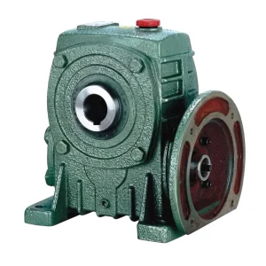
- Weight range: 5–350 kg across the full frame scale
- Reduction ratio: 1:10 to 1:60 (single stage)
- Double-input-shaft configuration for redundant motor arrangements
- Foot and flange mounting options for nacelle and hub integration
- Oil-bath lubrication; integral cast iron housing
- Operating temperature: −40°C to +40°C ambient

Cold Climate and Offshore Drive Reducer Specifications
Wind energy development has expanded aggressively into environments that impose far stricter equipment demands than early onshore installations in mild-climate regions. Offshore wind farms in the North Sea, Baltic Sea, and the growing Taiwan Strait and US East Coast developments operate in salt air with year-round humidity and frequent spray ingestion into the nacelle. Cold-climate onshore projects in northern Scandinavia, Canada, and Inner Mongolia encounter sustained temperatures below −30°C that challenge gear oil, seal elastomers, and bearing lubricant in equal measure.
For the single speed reducer in these environments, two specifications diverge from the standard WP-series default. The first is lubricant: PAO-based synthetic ISO VG 220 gear oil with a pour point below −45°C replaces standard mineral VG 220, maintaining pumpable viscosity at cold start and resisting oxidation over the 5-year oil change intervals that on-tower service economics demand. The second is seal compound: standard nitrile rubber (NBR) lip seals harden and lose flexibility below −25°C, allowing oil migration past the lip; fluorocarbon rubber (FKM) or low-temperature silicone seals maintain lip conformity to the shaft journal at −40°C and provide better resistance to the condensate contamination common in offshore nacelles. These two specification changes — lubricant and seal compound — account for the majority of the performance gap between a standard industrial worm gear reducer and a wind turbine duty unit without requiring structural changes to the housing or gear pair.
Position Holding and Passive Safety Locking in Turbine Drive Trains
One of the most practically significant characteristics of a single speed worm gear reducer in turbine applications is its passive position-holding capability at reduction ratios above 1:30. In the pitch drive, this means a blade driven to feather position by the emergency pitch system stays in that position without any sustained motor current, electromagnetic brake engagement, or control system activity. The aerodynamic moment from a 40–60 metre feathered blade — which attempts to rotate the blade back toward operating pitch — is insufficient to back-drive the worm mesh because the contact geometry between the worm thread and the bronze wheel tooth creates a friction lock that exceeds the back-driving force for any ratio above the self-locking threshold.
For the yaw drive, the self-locking property supplements the mechanical yaw brake. When the yaw controller completes a nacelle orientation manoeuvre and releases yaw brake pressure for a brief transition, the worm reducer prevents the nacelle from windvaning — rotating freely under asymmetric aerodynamic load — before the brake re-engages. This is not the primary yaw braking mechanism, which remains the dedicated yaw disk brake, but it provides a secondary holding function that reduces the demand on the brake caliper and extends brake pad service intervals. In turbine designs for markets including Germany, Denmark, the United Kingdom, and Texas — where yaw activity rates are high due to variable wind direction in complex terrain or offshore — this brake-supplementing characteristic of the worm reducer has measurable impact on O&M cost over a 20-year turbine service life.

Service Planning for Tower-Top and Hub Drive Reducers
Accessing a yaw drive reducer at tower-top height or a pitch drive reducer inside a rotating hub involves planning, equipment, and weather windows that are not required for equivalent ground-level industrial drives. This access cost is the primary reason wind turbine O&M teams prioritize long service intervals and low-frequency intervention counts for drive reducers over any other performance metric. A single speed reducer that requires gear oil changes every 12–18 months imposes a significant access cost burden over a 20-year turbine life; one that runs on synthetic PAO lubricant at 4–5-year change intervals is substantially more economical to maintain at tower height.
For pitch drive reducers specifically, the oil capacity of the unit determines how quickly the lubricant accumulates thermal degradation products during the high-cycle pitch activity of a busy wind site. A smaller oil volume heats and cools through a wider temperature range per cycle, accelerating oxidation. The WPZ and WPKZ compact oil-capacity variants with 0.4–5.2 L capacities suit smaller pitch drives where the hub compartment imposes strict volume limits; in these cases, synthetic lubricant with its superior oxidation resistance becomes even more important for reaching the target service interval without mid-term oil changes. Seal inspection and replacement — the other primary on-tower maintenance action — is scheduled at 8,000–12,000 hour intervals for correctly specified elastomer grades, which in a turbine running at 25–35% capacity factor corresponds to 3–5 years of operation between seal service visits.
Compatible Drive Components for Wind Turbine Systems
A complete yaw or pitch drive assembly requires components that are electrically and mechanically matched from motor output shaft through to the slew ring or pitch bearing engagement. Two product families pair directly with WP-series reducers and are available from the same supply source.


私たちについて
The manufacturing scope covers agricultural gearboxes, worm gear reducers, planetary gear drives, power take-off shafts, hydraulic cylinders, gears, chains, and motors — all produced within an ISO 9001:2015 certified quality framework. Design and production capacity extends across a broad portfolio of industrial and agricultural gearboxes and sub-assemblies manufactured in ductile iron, cast iron, cast steel, precision cast steel, and cast aluminum. Standard and non-standard mechanical components — including gears, sprockets, worm gears, pulleys, worms, and shafts — are fabricated in-house, enabling a complete one-stop supply model for renewable energy, infrastructure, and industrial drivetrain projects across global markets.
ワークショップ




よくある質問
編集者: PXY