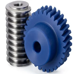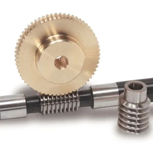
CNC機械用EPステンレス鋼ウォームギア
The EP-Stainless Steel Worm Gear series is engineered for high-precision CNC machinery, offering superior corrosion resistance and durability. Available in modules from 1.0 to 3.0, these gears support tooth counts ranging from 15 to 100, with bore diameters scaling from 6mm to 60mm (AH7 tolerance). Key models include the Module 1.0 (20T) with a 17mm pitch diameter and the robust Module 2.5 (40-60T) featuring a 20mm face width. Manufactured from premium Stainless Steel, they undergo advanced heat treatments like quenching & tempering to achieve a hardness of 55-60 HRC. With a standard 20° pressure angle and options for left/right hand twisting, these gears ensure smooth, backlash-free transmission.
CNC MACHINERY & INDUSTRIAL DRIVE COMPONENTS — WORM GEAR SERIES
CNC機械用EPステンレス鋼ウォームギア
A precision-machined steel worm gear and worm wheel series — stainless steel, carbon steel, brass, bronze, and alloy construction — hardness 55–60 HRC, pressure angle 20°, ISO standard sizing, and full heat treatment options, engineered for CNC machine tools, industrial reducers, and precision drive systems worldwide.
Technical Specifications — EP Steel Worm Gear and Worm Wheel Series
General product parameters for the EP series.
| パラメータ | EP Series Specification |
|---|---|
| Product Name | Worm Gear and Worm Wheel |
| Materials Available | Stainless Steel, Carbon Steel, Brass, Bronze, Iron, Aluminum Alloy, Copper, Plastic, Nylon, PA66, MC, PEEK, MSM, POM, Delrin |
| 熱処理 | Quenching and Tempering; Carburizing and Quenching; High-frequency Hardening; Carbonitriding |
| Surface Treatment | Carburizing and Quenching; Tempering; Tooth surface high-frequency quenching Hardening; Tempering |
| ボアタイプ | Finished bore; Pilot Bore; Special request |
| Processing Method | Molding, Shaving, Hobbing, Drilling, Tapping, Reaming, Manual Chamfering, Grinding |
| 圧力角 | 20° |
| Hardness | 55–60 HRC |
| Twisting Direction | L (Left) / R (Right) |
| Size Reference | Customer Drawings and ISO standard |
| Package | Wooden Case / Container and pallet; or made-to-order |
| Certificate | ISO9001:2008 |
Dimensional reference table — Module 1.0 to 3.0 worm wheel configurations (shaft bore AH7 1 mm increment). Dimensions B, C, D, E, F, G in mm.
| タイプ | モジュール | No. of Teeth | Straight Bore Ø (mm) | Keyway+Tap Bore Ø (mm) | Twist Dir. | B(mm) | C (mm) | D (mm) | F (mm) | G (mm) |
|---|---|---|---|---|---|---|---|---|---|---|
| Straight Bore / Keyway+Tap | 1.0 | 20 | 6 | 8 | L / R | 17 | 20 | 22 | 10 | 18 |
| 22–28 | 8 | 8–13 | 18–20 | 22–28 | 24–30 | |||||
| 30–48 | 10 | 10–17 | 25–30 | 30–48 | 32–50 | |||||
| 50–70 | 12 | 12–17 | 35–40 | 50–70 | 52–72 | |||||
| 80–100 | 15 | 15–30 | 50 | 80–100 | 82–102 | |||||
| Straight Bore / Keyway+Tap | 1.5 | 20–26 | 12 | 12–17 | 24–32 | 30–39 | 33–42 | 12 | 24 | |
| 28–44 | 15 | 15–30 | 36–50 | 42–67.5 | 45–70.5 | |||||
| 45–52 | 18 | 18–40 | 50–60 | 72–78 | 75–81 | |||||
| 60~100 | 20 | 20–50 | 60–70 | 90–150 | 93–153 | |||||
| Straight Bore / Keyway+Tap | 2.0 | 15–18 | 12 | 12–17 | 24–30 | 30–36 | 34–40 | 13 | 29 | |
| 20–28 | 15 | 15–22 | 32–45 | 40–56 | 44–60 | |||||
| 30–36 | 18 | 18–40 | 50 | 60–72 | 64–76 | |||||
| 40–48 | 20 | 20–44 | 60 | 80–96 | 84–100 | |||||
| 50–100 | 25 | 25–60 | 60~100 | 100–200 | 104–204 | |||||
| Straight Bore / Keyway+Tap | 2.5 | 15–18 | 15 | 15–30 | 30–38 | 37.5–45 | 42.5–50 | 14 | 34 | |
| 20–24 | 18 | 18–40 | 40–48 | 50–60 | 55–65 | |||||
| 25–36 | 20 | 20–50 | 50–70 | 62.5–90 | 67.5–95 | |||||
| 40–60 | 25 | 25–70 | 70–80 | 100–150 | 105–155 | |||||
| Straight Bore / Keyway+Tap | 3.0 | 15–18 | 18 | 18–22 | 36–40 | 45–54 | 51–60 | 16 | 41 | |
| 20–28 | 20 | 20–40 | 45–55 | 60–84 | 66–90 | |||||
| 30–60 | 25 | 25–70 | 60–80 | 90–180 | 96–186 |
B = hub width (mm) · C = face width (mm) · D = pitch diameter (mm) · F = hub diameter (mm) · G = outside diameter (mm). All bore sizes AH7 tolerance, 1 mm increment. E column = keyway+tap bore, available on request. Contact engineering team for Module 3.5 and above.
What Is a Steel Worm Gear — And Why Stainless Steel for CNC Applications?
A steel worm gear is a helical drive component pairing a worm screw (the driving element) with a worm wheel (the driven element) to transmit torque between two shafts arranged at 90° to each other. The worm thread engages the worm wheel tooth flanks under a sliding contact, achieving high reduction ratios in a single compact stage while generating a self-locking effect at low lead angles. Among metal worm gear materials, stainless steel occupies a specific performance niche: it delivers the corrosion resistance of a passive oxide layer alongside the structural strength of an engineered steel alloy, making the stainless steel worm gear the standard selection for CNC machine tools, food processing equipment, pharmaceutical production lines, marine drives, and chemical plant actuators where carbon steel would rust or contaminate the process environment.
The EP series steel worm gear and worm wheel set is specified as Worm Gear and Worm Wheel, with a comprehensive material portfolio: Stainless Steel, Carbon Steel, Brass, Bronze, Iron, Aluminum Alloy, Copper, Plastic, Nylon, PA66, MC, PEEK, MSM, POM, and Delrin. Heat treatment options include Quenching and Tempering, Carburizing and Quenching, High-frequency Hardening, and Carbonitriding. Surface treatment includes Carburizing and Quenching, Tempering, and Tooth surface high-frequency quenching Hardening and Tempering. Bore configurations cover Finished bore, Pilot Bore, and Special request. Processing methods span Molding, Shaving, Hobbing, Drilling, Tapping, Reaming, Manual Chamfering, and Grinding. Pressure angle is a standard 20°, hardness 55–60 HRC, sizing to Customer Drawings and ISO standard, packaged in Wooden Case / Container and pallet or made-to-order, certified to ISO9001:2008.
For CNC machine tool builders and industrial machinery OEM procurement teams in Germany, Japan, Canada, South Korea, and Australia, the EP steel worm gear series delivers a single-source supply solution that covers both the stainless steel worm gear for corrosive environments and the case-hardened carbon steel worm gear for maximum load capacity — within the same dimensional standard, the same ISO quality framework, and the same lead time structure.
Five Reasons to Specify a Stainless Steel Worm Gear
① 55–60 HRC Surface Hardness — Long-Cycle Fatigue Life
At 55–60 HRC, the EP series steel worm gear tooth surface operates in the hardness range where both contact fatigue resistance and bending fatigue strength are substantially above those of through-hardened or normalised steel. High-frequency hardening and carburizing and quenching processes localise this hardness to the tooth flank and root, leaving the core tough enough to absorb shock loads without brittle fracture. For CNC machine tool worm drive stages running at 500–1,500 RPM input speeds, this surface hardness specification is the primary factor governing gear service life before the surface fatigue limit is reached — which is why it is specified first in the EP series data sheet.
② Corrosion-Resistant Stainless Steel — No Coating Required
A stainless steel worm gear's passive oxide layer — the Cr₂O₃ film that forms spontaneously on austenitic stainless (304/316) and martensitic stainless grades — provides corrosion resistance in humid, washdown, and mild chemical environments without the coating thickness variation that affects backlash in plated carbon steel worm gear sets. In food processing, pharmaceutical, and marine drive applications in the UK, Canada, and Australia, the stainless worm gear eliminates the re-plating maintenance intervals that are a recurring cost in carbon steel drives exposed to moisture or sanitising chemicals.
③ Complete Heat Treatment Portfolio
The breadth of heat treatment options in the EP series — Quenching and Tempering for through-hardness, Carburizing and Quenching for case hardness with tough core, High-frequency Hardening for selective tooth surface hardening, and Carbonitriding for improved wear resistance at moderate hardness — allows the correct treatment to be matched to each application's combination of surface contact stress, core bending stress, and operating temperature. This is not a commodity gear range with a single heat treatment applied uniformly; it is an engineered steel worm gear production system that matches metallurgical process to application duty.
④ Full Processing Capability — Finished Bore to Special Request
Bore configurations spanning Finished bore, Pilot Bore, and Special request — combined with processing methods including Hobbing, Shaving, Grinding, Drilling, Tapping, Reaming, and Manual Chamfering — mean the EP steel worm gear can be delivered ready to mount on customer shafts without secondary machining operations at the customer's facility. Keyway and tap configurations are available across the full module and tooth count range, saving assembly time and reducing in-house machining cost for machine tool builders and industrial gearbox OEM customers globally.
⑤ ISO Standard Sizing — Multi-Market Interchangeability
Sizing to Customer Drawings and ISO standard means EP series steel worm gear sets are dimensionally interchangeable with existing ISO-compliant worm gear drives in machine tools built to DIN, JIS, and AGMA standards. For maintenance procurement teams replacing worn worm gear sets in CNC machine tools in Germany, Japan, Canada, and Australia, this ISO traceability eliminates the fit-and-function verification burden that would arise if the replacement gear came from a non-standard dimensional reference system. ISO9001:2008 factory certification provides the auditable quality system background that regulated OEM supply chains require.
Material Portfolio — Stainless Steel and Beyond
The EP steel worm gear series covers the full spectrum of metal and polymer worm gear materials in a single product family. Understanding the material hierarchy helps engineering and procurement teams match the correct worm gear material to each application's combination of load, speed, environment, and regulatory requirements without the cost of over-specifying a premium material where a standard grade would perform equally well.
Stainless Steel — Corrosion-Critical Environments
Austenitic grades (304, 316) for maximum corrosion resistance in food, pharmaceutical, and marine environments; martensitic grades (420, 440C) for higher hardness in the 50–58 HRC range where both wear resistance and corrosion protection are required. The stainless steel worm gear is the standard material for regulated food processing and pharmaceutical drives globally.
Carbon Steel — Maximum Load Capacity
Carburized and quenched low-alloy carbon steel (20CrMnTi equivalent) achieves case hardness of 55–60 HRC over a tough core — the highest available fatigue life for a given tooth module. Carbon steel worm gear sets are specified for industrial gearboxes, CNC machine tool drives, and heavy-duty actuators where load capacity is the primary specification and the environment does not present corrosion risk requiring a stainless grade.
Brass and Bronze — Precision Instrument Drives
Brass and phosphor bronze worm wheels against hardened steel worm screws represent the traditional precision instrument worm drive pairing — low friction, excellent machinability at small module sizes, and natural corrosion resistance without coating. A metal worm gear set in this material combination is specified for telescope drives, scientific instruments, and camera positioning mechanisms where lubricant-free or low-lubricant operation is required.
Polymer Options — Lightweight and Lubricant-Free
Nylon, PA66, POM (Delrin), PEEK, and MSM polymer worm wheels provide lubricant-free mesh operation, significant weight reduction, and corrosion immunity for light-to-moderate duty drives. A plastic worm gear or nylon worm gear against a steel worm screw is specified in office automation, medical device sub-assemblies, and agricultural actuators where lubricant contamination risk or corrosion immunity outweigh the load capacity limitation of polymer materials relative to metal worm gear alternatives.
How a Steel Worm Gear Works — Mechanism and Design Considerations
The purpose of a worm gear is to transmit torque between two shafts at 90° to each other while achieving a high speed reduction ratio in a single, compact gear stage. In the EP steel worm gear set, the worm screw — a precision-hobbed and ground helical thread — drives the worm wheel by pushing against the tooth flanks under a predominantly sliding contact at the 20° pressure angle. The thread advances the worm wheel by exactly one tooth pitch per worm revolution: a worm wheel with 30 teeth produces a 30:1 reduction from a single-start worm, allowing significant speed reduction and torque multiplication in a package that no spur or helical gear stage can match at equivalent tooth pitch diameter.
A practical question that arises when specifying a worm drive is: can a worm gear go both directions? The answer is yes — the worm can drive the wheel in either direction of rotation depending on the worm thread hand (Left or Right, both available in the EP series) and the motor rotation direction. What limits directionality in some worm gear configurations is the self-locking property at low lead angles: when the worm's helix angle is below the arctangent of the mesh friction coefficient, back-driving of the worm by the wheel load is prevented — the drive is irreversible. The EP series specifies both L (Left) and R (Right) twisting directions across all module ranges, supporting bidirectional drive configurations in conveyor reversing systems, crane hoists, and CNC axis drives where motor reversal is a standard operating mode.
The 20° pressure angle used throughout the EP steel worm gear series is the standard for industrial worm gear drives, providing a balance between tooth strength and axial thrust at the worm bearings. The sliding contact at the worm mesh generates significant heat under sustained high-load operation — which is why proper lubrication with EP (extreme pressure) gear oil is essential for the metal worm gear configuration, and why the polymer variants in the series (nylon worm gear, plastic worm wheel) provide an inherent advantage in low-to-moderate duty applications where lubricant elimination is a priority. What are the disadvantages of worm gears? The main disadvantages are lower efficiency than helical or spur gear stages at equivalent ratios (typically 60–85% for a single-start worm vs 95%+ for helical), and heat generation under high-duty continuous operation that must be managed through oil bath lubrication or thermal derating of the continuous torque rating.
Application Scenarios — Where Steel Worm Gears Are Specified
The EP steel worm gear series covers the full range of applications where a right-angle drive, high reduction ratio, and metal construction are required simultaneously. The sectors below define the primary markets served by the EP series globally.
CNC Machine Tool Axes and Rotary Tables
CNC machining centre rotary tables, 4th/5th axis units, and tilting rotary tables use steel worm gear reducers for their combination of compact right-angle drive, high gear reduction ratio, and self-locking position hold when the servo is de-energised. A carburized and quenched steel worm gear at 55–60 HRC provides the surface fatigue life needed for continuous CNC duty at 500–1,500 RPM worm input speeds in machine tool factories across Germany, Japan, South Korea, and Canada.
Food Processing and Pharmaceutical Lines
Conveyor drives, filling head actuators, capping mechanisms, and mixing tank agitators in food processing and pharmaceutical production specify stainless steel worm gears (304 or 316 grade) for their corrosion resistance to cleaning agents, sanitisers, and process fluids. The stainless worm gear eliminates the coating failure risk that makes carbon steel drives unsuitable in washdown production environments in the UK, Germany, and Australia regulated under EU food equipment standards and FDA 21 CFR requirements.
Industrial Stainless Steel Gear Reducers
Chemical plant process valve actuators, wastewater treatment equipment, and offshore platform drives specify stainless steel gear reducer configurations using the EP series metal worm gear for their resistance to H₂S, chloride environments, and process chemical exposure. The stainless worm gear in 316L grade provides adequate pitting resistance in chloride-bearing environments encountered in coastal industrial facilities in Canada, Australia, and South Korea where carbon steel reducer housings would corrode within a single maintenance interval.
Crane Hoists and Material Handling
Overhead crane end-truck drives, hoist drum gearboxes, and conveyor head shaft reducers use carbon steel worm gear sets at 55–60 HRC for their load capacity, self-locking braking effect under load, and compact right-angle housing geometry. The self-locking property of a low-lead-angle steel worm gear prevents the load from back-driving the motor when power is removed, providing an intrinsic load-holding brake function without an additional mechanical brake in many hoist configurations.
Agricultural and Outdoor Machinery
Seed drill actuators, irrigation valve positioners, and implement direction change gearboxes use steel worm gear sets for their right-angle drive compactness and self-locking position hold in outdoor field conditions. In agricultural equipment operating in Canada, Brazil, and Australia, the metal worm gear provides the structural durability and load capacity that polymer alternatives cannot match in high-torque implement drive positions, while the stainless grade extends service life in wet-field and fertiliser-spray environments without rust-related seizure.
Marine and Offshore Equipment
Deck machinery drives, stabiliser fin actuators, windlass gearboxes, and navigation instrument positioners on vessels and offshore platforms specify stainless worm gear sets for their resistance to continuous salt spray, immersion, and marine atmospheric corrosion. A stainless steel worm gear in 316 grade maintains its dimensional accuracy and mesh quality over multi-year service intervals in marine environments where any form of uncoated carbon steel drive would require quarterly replacement in harsh saltwater operating conditions.
Related Products — Complete Drive System from One Source
Beyond the EP steel worm gear series, we produce the complementary drive components that complete a full drive train specification — all manufactured under the same ISO-certified quality system and available from a single supplier.
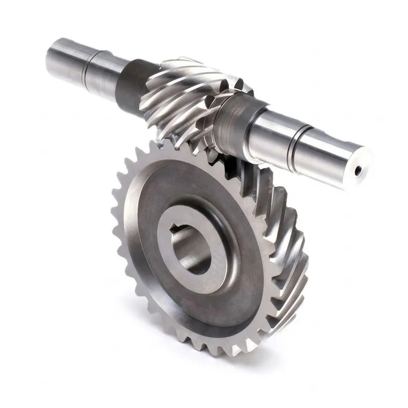
ダブルヘリカルギア
In multi-stage drive trains where a steel worm gear stage handles the final right-angle reduction, a double helical gear is commonly used upstream at the motor output to provide an efficient first-stage speed reduction. The opposing helix angles of the double helical gear cancel axial thrust, keeping upstream bearing design simple while delivering the load capacity the motor-adjacent stage requires. Our double helical gear series is dimensionally compatible with the EP worm drive portfolio, enabling single-supplier procurement for the full drive chain from motor output to load shaft.

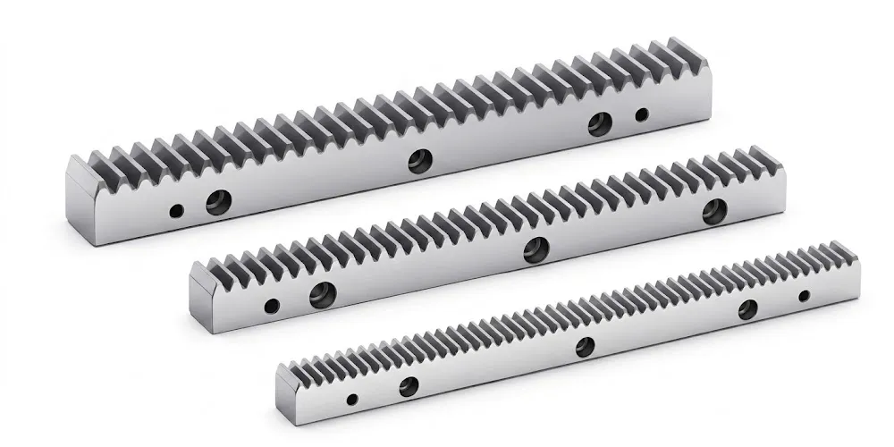
Gear Rack — Full Series
Where the rotary output of a steel worm gear reducer drives a linear axis — as in a CNC gantry, a robotic linear slide, or a precision positioning table — our gear rack series provides the matching pinion-to-rack interface at the output. Metric module steel and stainless steel racks are available across module sizes compatible with the pinion spur gear on the worm wheel output shaft, supporting single-source procurement for both the right-angle worm reduction stage and the linear output drive in CNC and automation machine builds.
Order and Trade Information
Minimum Order Quantity
Standard steel worm gear sets carry a baseline MOQ. Mixed configurations — different module sizes, material grades, bore types, and tooth counts — can be combined into a single order totalling approximately USD 1,500. For new programme evaluation, 1–5 pcs samples are available at sample pricing. Very small orders of 1–2 pcs for urgent spare or prototype requirements can be assessed individually, with per-unit cost higher at sub-baseline quantities.
Lead Time
Standard catalogued steel worm gear configurations: 10–25 working days. Standard parts with bore modification or keyway machining: 15–35 working days. Custom OEM configurations from customer drawing: 20–45 working days. High-precision ground or heat-treated configurations: 30–60 working days. Sample and test-piece orders (1–5 pcs): 7–25 working days, with complex configurations assessed individually before production release.
Incoterms and Payment
Standard component orders: EXW, FOB, CIF, and DAP available. Samples and urgent spare parts: EXW / FCA / DAP / courier service. FCA, CFR, CPT, CIP, and DDP negotiable for established procurement programmes or specific import markets. Payment: T/T (bank transfer) and L/C (letter of credit) both accepted. Packing: Wooden Case / Container and pallet, or made-to-order packaging for precision or sensitive configurations.
OEM / Custom Programme
Full OEM and custom steel worm gear production from customer engineering drawings, DXF/DWG files, or physical samples for reverse engineering. MOQ for custom configurations depends on material grade, heat treatment process, bore type, tooth count, and module. Drawing approval precedes production release. Full dimensional and material certification documentation is provided at delivery, with heat treatment certificates available on request for regulated supply chain programmes.
About Our Manufacturing Capability
With more than ten years of focused experience in precision mechanical power transmission, our production facility designs and manufactures a comprehensive range of industrial drive components under a single ISO 9001:2015 certified quality management framework. Our manufacturing portfolio covers agricultural gearboxes, worm gear reducers, planetary drive systems, power take-off shafts, hydraulic cylinders, drive chains, gears of all types, and industrial motors — all developed in-house with full dimensional traceability.
Structural manufacturing capabilities cover ductile iron, grey cast iron, cast steel, precision cast steel, and cast aluminium for gearbox housings, large gear blanks, and custom assemblies. Our component range includes gears, sprockets, worm gears, pulleys, shafts, worms, and a full spectrum of standard and non-standard mechanical parts. For the EP steel worm gear series, we operate CNC gear hobbing, worm grinding, and heat treatment equipment covering the full module and bore range documented in the specification table, including all four heat treatment processes: Quenching and Tempering, Carburizing and Quenching, High-frequency Hardening, and Carbonitriding.
ワークショップ




よくある質問
編集者: PXY