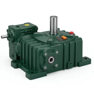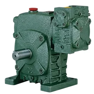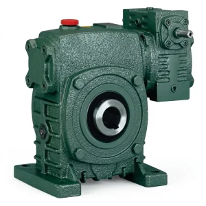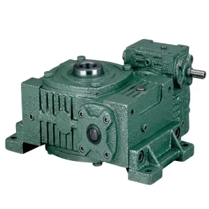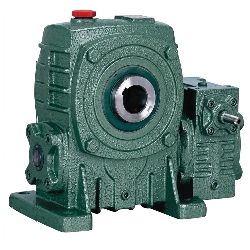
EP-WPEKA dubbele snelheidsreductor
De EP-WPEKA is een speciaal ontworpen dubbele wormwielreductor die zich onderscheidt door zijn holle uitgaande boring. Dankzij dit ontwerp kan de aangedreven as direct door de behuizing van de tandwielkast lopen in plaats van aan een massieve as te worden gekoppeld. Deze doorlopende boring is met name waardevol in transportband- en roerwerktoepassingen waar nauwe toleranties voor de uitlijning van de as vereist zijn en de axiale ruimte beperkt is. De serie omvat ingangsvermogens van instapmodellen tot 5,5 kW en een uitzonderlijk breed gewichtsbereik, van 20 kg bij het compacte 40-70 frame tot 462 kg bij het zwaarste 155-250 frame. Hierdoor is er altijd een correct gedimensioneerde oplossing beschikbaar, ongeacht de koppelbehoefte van de toepassing.
De trapsgewijs opgebouwde dubbele wormwieloverbrenging levert reductieverhoudingen van 1/200 tot 1/900, waardoor zeer lage uitgangssnelheden mogelijk zijn met een standaard 4-polige inductiemotor zonder externe tussenassen of riemoverbrengingen. Drie asrichtingen – A, B en C – bieden ruimte voor verschillende toepassingen, met zowel enkelvoudige als tegenovergestelde asconfiguraties. Voor inkopers die een dubbele wormwieloverbrenging vergelijken met een planetaire overbrenging of een kegelwieloverbrenging, zijn de belangrijkste voordelen van de WPEKA de compacte afmetingen, de inherente zelfvergrendeling van de uitgaande as en de aanzienlijk lagere kostprijs per overgedragen kilowatt bij zeer hoge reductieverhoudingen.
Industriële krachtoverbrenging · Dubbele snelheidsserie
EP-WPEKA dubbele snelheidsreductor
Een tweetraps holle uitlaatboring dubbele snelheidsreductor Ontworpen voor industriële aandrijvingen met hoog koppel en lage snelheid — met twee wormwieloverbrengingen in één robuuste gegoten behuizing, van een lichtgewicht instapmodel van 20 kg tot een zwaar uitgevoerde unit van 462 kg die geschikt is voor continu gebruik in de meest veeleisende productieomgevingen wereldwijd.
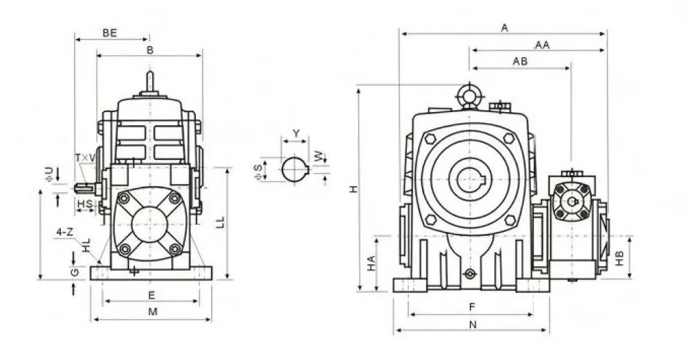
Technische specificaties — EP-WPEKA dubbele snelheidsreductorserie
Alle buitenmaten in mm. Gewicht in kg. De vermelde verhoudingen zijn representatief per framemaat.
| Dubbele snelheidsreductor | Verhouding | A | AA | AB | B | ZIJN | HL | LL | H | HA | HB | M | N | E | F | Z | Uitgangsboring B×Y (mm) | Ingaande as T×V (mm) | Gewicht (kg) |
|---|---|---|---|---|---|---|---|---|---|---|---|---|---|---|---|---|---|---|---|
| 40-70 | 1/200 | 286 | 195 | 153 | 130 | 87 | 110 | 140 | 236 | 70 | 50 | 150 | 190 | 115 | 150 | 20 | 8×33.3 | 4×2,5 | 20 |
| 50-80 | 1/300 | 297 | 197 | 144 | 150 | 108 | 130 | 160 | 268 | 80 | 65 | 170 | 220 | 135 | 180 | 20 | 10×38.3 | 4×2,5 | 27 |
| 60-100 | 1/400 | 363 | 231 | 175 | 160 | 120 | 160 | 200 | 336 | 100 | 75 | 190 | 270 | 155 | 220 | 25 | 12×43.3 | 5×3 | 44 |
| 70-120 | 1/500 | 408 | 256 | 193 | 175 | 140 | 190 | 240 | 430 | 120 | 90 | 230 | 320 | 180 | 260 | 30 | 14×48,8 | 5×3 | 73 |
| 80-135 | 1/600 | 471 | 298 | 226 | 210 | 160 | 215 | 270 | 480 | 135 | 105 | 250 | 350 | 200 | 290 | 30 | 18×64,4 | 7×4 | 101 |
| 100-155 | 1/800 | 555 | 354 | 269 | 256 | 190 | 235 | 290 | 531 | 135 | 130 | 275 | 390 | 220 | 320 | 35 | 20×74,9 | 7×4 | 144 |
| 120-175 | 1/900 | 598 | 379 | 287 | 282 | 219 | 280 | 335 | 600 | 160 | 155 | 310 | 430 | 250 | 350 | 40 | 22×85,4 | 7×4 | 201 |
| 135-200 | — | 662 | 425 | 318 | 320 | 256 | 310 | 375 | 666 | 175 | 185 | 360 | 480 | 290 | 390 | 40 | 22×90.4 | 10×4,5 | 293 |
| 155-250 | — | 795 | 510 | 380 | 400 | 295 | 355 | 450 | 800 | 200 | 203 | 460 | 560 | 380 | 480 | 45 | 28×116,4 | 12×5 | 462 |
De afmetingen van de uitgaande as worden weergegeven als W×Y (boringsdiameter × boringdiepte, mm). De afmetingen van de ingaande as als T×V (spiebreedte × spiediepte, mm). Neem contact op met ons technische team voor overbrengingsverhoudingen die niet in de catalogus staan en voor aangepaste boringconfiguraties.
Vijf belangrijke voordelen van de EP-WPEKA dubbele snelheidsreductor
Ontwerp van de holle uitlaatboring
In tegenstelling tot tandwielkasten met een massieve as, accepteert de holle boring van de WPEKA dubbele snelheidsreductor de aangedreven as direct door de behuizing. Dit elimineert koppelingen die uitlijningsfouten veroorzaken en reduceert de totale axiale lengte van de aandrijflijn. Deze configuratie heeft de voorkeur voor transportbandassen en mengasfalten in de voedingsmiddelen-, grondstoffen- en chemische industrie.
Ultrahoge reductie in één stap
Door de trapsgewijs geschakelde dubbele wormwieloverbrenging worden overbrengingsverhoudingen tot 1/900 bereikt binnen één compacte behuizing. Dit zou anders twee aparte tandwielkasten in serie, extra asverbindingen en aanzienlijk meer vloeroppervlak vereisen. Het resultaat is een overzichtelijker machineontwerp en minder potentiële storingspunten in de aandrijflijn.
Drie configureerbare asrichtingen
Configuraties A, B en C omvatten enkelzijdige en dubbelzijdige in- en uitgangen, waardoor machineontwerpers de vrijheid hebben om aandrijvingen om obstakels heen te leiden en tandwielkasten in te passen in beperkte structurele ruimtes. Deze flexibiliteit maakt de WPEKA tot een voorkeursproduct. dubbele wormwielaandrijving Voor renovatieprojecten waarbij een nieuwe unit moet passen op een bestaande locatie.
Ingebouwde lastbevestiging
De inherente zelfvergrendelende eigenschap van het wormwielpaar – waarbij de uitgang de ingang niet kan terugduwen wanneer de spiraalhoek onder de wrijvingsdrempel komt – maakt een aparte rem overbodig bij verticaal belaste of hellende aandrijvingen. Dit vereenvoudigt de elektrische installatie en verlaagt de totale systeemkosten, met name bij hef- en poortaandrijvingen in het Verenigd Koninkrijk en Canada.
Wereldwijde OEM-leveringsketen klaar
De WPEKA wordt geproduceerd onder ISO 9001:2015-certificering met gestandaardiseerde IEC-motorflenzen voor het volledige vermogensbereik en wordt geleverd aan geverifieerde OEM-kopers in Australië, Nederland, Brazilië, Zuid-Korea, Colombia, Canada en het Verenigd Koninkrijk met volledige documentatie over de traceerbaarheid van materialen. Hierdoor is het eenvoudig om bij de eerste aankoop te voldoen aan de lokale inkoopvoorschriften.

Hoe de dubbele wormwielaandrijving werkt
Het werkingsprincipe van de WPEKA dubbele snelheidsreductor is gebaseerd op twee onafhankelijke wormwieloverbrengingen die in serie zijn geschakeld in dezelfde gegoten behuizing. De rotatiekracht komt binnen via de ingaande as – die direct is verbonden met de primaire worm – die een hoek van 90° maakt met het primaire wormwiel. Het wiel is via een spie verbonden met een tussenliggende as, waarop de secundaire worm is gemonteerd. De secundaire worm grijpt op zijn beurt in op het secundaire wormwiel, dat is gemonteerd op de holle uitgaande as. Deze sequentiële dubbele overbrenging zorgt ervoor dat elke trap zijn eigen reductie levert, en het gecombineerde effect daarvan resulteert in de totale overbrengingsverhouding die op het typeplaatje staat vermeld.
Een praktisch gevolg van dit trapsgewijze ontwerp is dat de uitgaande as extreem langzaam roteert ten opzichte van de motor — tot een fractie van een omwenteling per minuut bij de hoogste overbrengingsverhoudingen — terwijl het koppel dat in elke trap wordt vermenigvuldigd ervoor zorgt dat de uitgang aanzienlijke radiale en axiale belastingen van de aangedreven as die door de boring loopt, kan verwerken. dubbele wormwieloverbrenging De geometrie beperkt ook het maximaal theoretische rendement van de unit (doorgaans 50–70 TP4T over de cascade), wat betekent dat thermisch beheer een belangrijke ontwerpfactor is voor toepassingen met continu gebruik en hoog vermogen. Voor de meeste toepassingen met een lichte tot middelhoge cyclus biedt de geribbelde gegoten behuizing voldoende oppervlakte om de gegenereerde warmte binnen veilige bedrijfslimieten af te voeren.
De zelfvergrendelende eigenschap ontstaat doordat spoedhoeken van de wormdraad kleiner dan ongeveer 5° voorkomen dat het wiel de worm in omgekeerde richting draait onder invloed van zwaartekracht of procesbelastingen. Dit is een kenmerk van de dubbele uitgaande wormwieloverbrenging Het is een geometrie die inherent is aan de wormwieloverbrenging en geen apart component, en daarom schrijven ontwerpers de WPEKA dubbele snelheidsreductor voor wanneer een onbekrachtigde lastvasthoudfunctie zonder secundaire rem moet worden gegarandeerd.
Materialen en constructienormen voor dubbelsnelheidsreductoren
De behuizing van de WPEKA dubbele snelheidsreductor is gegoten in hoogwaardig grijs gietijzer, dat voornamelijk is gekozen vanwege de uitstekende trillingsdemping en de stabiliteit bij de temperatuurschommelingen die optreden tijdens continu industrieel gebruik. Voor omgevingen met hoge impact of corrosieve omstandigheden – zoals die voorkomen in de Australische mijnbouw, de Colombiaanse grindverwerking en de Nederlandse waterzuiveringsinstallaties – kunnen in de ontwerpfase behuizingen van nodulair gietijzer en gegoten staal worden gespecificeerd om de slagvastheid te verhogen tot boven wat grijs gietijzer betrouwbaar kan bieden.
Beide wormassen – primair en secundair – zijn vervaardigd uit gehard staal, doorgehard in de kern en oppervlaktegehard tot 58–62 HRC na carboneren. De schroefdraadflanken zijn nauwkeurig geslepen volgens de DIN 3975-nauwkeurigheidsklassen, die het contactpatroon met het bronzen wiel bepalen en direct van invloed zijn op het loopgeluid en de levensduur. De wormwielen zijn centrifugaal gegoten in fosforbrons met een hoog tingehalte, gefreesd om in te grijpen met de geharde stalen worm en gemonteerd op de tussen- en uitgaande assen met behulp van spieën met perspassing. De materiaalcombinatie – stalen worm op bronzen wiel – is de standaard voor fabrikanten van wormwielreductoren wereldwijd, omdat het zorgt voor gecontroleerde inloopslijtage die het contact tijdens de eerste gebruiksfase verbetert, terwijl de dimensionale stabiliteit daarna behouden blijft.
De oppervlakken van de uitgaande asboring zijn afgewerkt met een H7-tolerantie om standaard interferentie- of glijpassing met de aangedreven as mogelijk te maken. Er kan gekozen worden uit diepgroefkogellagers aan de ingang en hoekcontact- of kegelrollagers aan de uitgang, wat zorgt voor voldoende axiale draagkracht voor de radiale krachten die ontstaan wanneer de holle boring de cantileverbelasting van de aangedreven as opvangt. De buitenafwerking bestaat uit een tweelaags primer- en toplaagsysteem, verkrijgbaar in de standaard groene kleur die kenmerkend is voor dit type product. wormenmestverkleiner productlijn, of in alternatieve blauw-witte opties voor faciliteitsspecifieke kleurcoderingseisen.

Toepassingsscenario's voor dubbelsnelheidsreductoren
De doorvoeropening van de WPEKA dubbele snelheidsreductor Dit opent toepassingsmogelijkheden die niet beschikbaar zijn met een conventionele tandwielkast met korte as. De volgende sectoren vertegenwoordigen de belangrijkste implementatieomgevingen voor deze serie bij onze gevestigde wereldwijde klantenkring.
🥁 Schroef- en vijzeltransporteurs
Graanelevators, cementschroefvoeders en vijzeltransporteurs voor kunststofkorrels profiteren van de holle boring van de WPEKA dubbele snelheidsreductor, omdat de vijzelas direct door de tandwielkast glijdt, waardoor een aparte uitgaande koppeling en asadapter overbodig zijn. Deze configuratie is standaard in Australische graanexportterminals en Canadese kunstmestmenginstallaties, waar bij de vervanging van transportbanden vaak voor dit type aandrijving wordt gekozen.
🔄 Aandrijvingen voor roerwerken en agitators
Roerwerken voor afvalwaterzuivering, roerwerken voor fermentatietanks en mengvaten voor verf zijn typische toepassingen voor de WPEKA, omdat de doorlopende boring ervoor zorgt dat de roeras tot elke gewenste diepte in het vat kan worden gestoken zonder extra koppelingsonderdelen boven de versnellingsbak. wormwieloverbrenging met hoog koppel Een output bij een zeer laag toerental is precies de bedrijfsomstandigheid die deze toepassingen jarenlang continu vereisen in de Nederlandse en Britse chemische sector.
🏗️ Poort- en klepactuatoren
Schuifafsluiteraandrijvingen, vlinderklepactuatoren en industriële sluitmechanismen van de WPEKA dubbele snelheidsreductor gebruiken de zelfvergrendelende uitgang om de schuifpositie vast te houden wanneer de stroom is uitgeschakeld – een belangrijke veiligheidsfunctie voor waterbeheersings- en irrigatie-infrastructuur in Brazilië en Colombia. zware wormwielaandrijving versnellingsbak De frames (135-200 en 155-250) worden het meest gebruikt voor installaties met grote poortactuatoren waarbij ook aan de vereisten voor handmatige bediening met koppel moet worden voldaan.
📦 Indexerings- en positioneringstabellen
Roterende indexeertafels en servoloze positioneringssystemen in de lichte industrie maken gebruik van kleinere WPEKA-frames (40-70 tot en met 70-120) om nauwkeurige, herhaalbare bewegingen tussen stations te realiseren met een gewone inductiemotor. De extreem hoge overbrengingsverhouding – in combinatie met de boring voor de centrale as van de tafel – is een praktisch alternatief voor dure servogestuurde planetaire motoren voor toepassingen die geen dynamische herpositionering vereisen in de Zuid-Koreaanse elektronica-assemblage- en verpakkingsindustrie.
🌾 Landbouwverwerkingsapparatuur
Wortelgroentewasmachines, voermengers en machines voor het langzaam keren van gewassen maken gebruik van de robuuste behuizing en de zelfvergrendelende eigenschap van de WPEKA dubbele snelheidsreductor. Landbouwmachines worden blootgesteld aan schokken en ongelijkmatige belastingen die de stijfheid van de behuizing op de proef stellen. De dikwandige gegoten wanden en de brede lagerafstand van de WPEKA dubbele snelheidsreductor zijn bestand tegen deze omstandigheden gedurende een lange levensduur, zonder de vermoeidheidsscheuren die bij dunnere concurrerende modellen in veeleisende landbouwmachines in het Verenigd Koninkrijk en Australië worden waargenomen.
Over onze productiefaciliteit
Met meer dan tien jaar opgebouwde expertise in mechanische krachtoverbrenging produceert onze fabriek een geïntegreerd portfolio aan aandrijfcomponenten: landbouwversnellingsbakken, wormwieloverbrenging snelheidsreductorenPlanetaire tandwieloverbrengingen, aftakasassen, hydraulische cilinders, precisietandwielen, rollenkettingen en elektromotoren. Dankzij deze productbreedte begrijpen we hoe de WPEKA functioneert binnen een echt machinesysteem – niet slechts als een losstaand catalogusartikel – en dat operationele perspectief vormt de basis voor elke dimensionale en materiaalkeuze in het productieproces.
Wij produceren volgens de ISO 9001:2015-norm, die van toepassing is op alle productiestadia: controle van de grondstoffen, kwaliteitscontrole van het gietwerk, bewerking, assemblage en eindinspectie. Onze fabricagemogelijkheden omvatten behuizingen van nodulair gietijzer, gietijzer, gegoten staal, precisiegegoten staal en gegoten aluminium, evenals de interne productie van tandwielen, kettingwielen, wormwielen, poelies, wormassen en een breed scala aan standaard en niet-standaard transmissiecomponenten. OEM-leverancier van dubbele snelheid wormwielreductoren Verzoeken – met betrekking tot aangepaste verhoudingen, niet-standaard boringmaten en speciale montagevoeten – worden routinematig afgehandeld als onderdeel van onze normale engineeringworkflow, in plaats van als uitzonderingen die langdurige goedkeuringsprocedures vereisen.
Workshop




Gerelateerde producten en compatibele componenten
A dubbele snelheidsreductor Het systeem presteert het best wanneer de in- en uitgangen correct op elkaar zijn afgestemd. De twee onderstaande productcategorieën zijn de meest voorkomende combinaties van componenten en zijn verkrijgbaar bij dezelfde leverancier. Dit elimineert de dimensionale onzekerheid die ontstaat wanneer een motor bij de ene leverancier en een versnellingsbak bij een andere leverancier worden ingekocht.

Elektromotoren
Standaard IEC-frame inductiemotoren in B3-, B5- en B14-montageconfiguraties, beschikbaar voor het volledige WPEKA-ingangsvermogensbereik. De ingangsflenzen zijn machinaal bewerkt om direct aan te sluiten op de gestandaardiseerde motorsteun van de WPEKA, waardoor de juiste asinsteekdiepte en concentriciteit gegarandeerd zijn zonder dat er ter plaatse adapters nodig zijn. elektrische motoren dubbele snelheid wormwielreductor De combinatie die als een bijpassende set wordt besteld, wordt voorgemonteerd en testgedraaid verzonden, waardoor de installatietijd op locatie wordt verkort.

Wormwieloverbrenging
Naast de tweetraps WPEKA, de enkelvoudige reductie nmrv wormremmerDe WP- en WPS-families bestrijken overbrengingsverhoudingen van 1/5 tot 1/100 voor toepassingen die niet de extreem hoge overbrengingsverhouding van de tweetrapsunit vereisen. Of u nu een compacte unit nodig hebt... wormwielreductieset voor een positioneringsactuator voor lichte toepassingen of een hoogwaardige wormenremmer Voor een transportband die continu in bedrijf is, voldoet het eentrapsassortiment aan die eisen, terwijl dezelfde flensnormen als de WPEKA worden gehanteerd.
Veelgestelde vragen
Vraag 1 — Waarom is een dubbeltoerenreductor met holle boring, zoals de EP-WPEKA, beter geschikt dan een tandwielkast met massieve as voor industriële schroefbandtransporteurs in Australië?
De holle boring van de doorlopende as elimineert de aparte uitgaande koppeling volledig: de aangedreven schroefas schuift eenvoudigweg door de boring van de versnellingsbak en wordt aan de uitgangszijde vergrendeld met een spiebaan. Dit elimineert een mogelijke uitlijningsfout, verkort de totale lengte van de aandrijfeenheid en vermindert het aantal onderdelen bij de installatie. Bij transportbandaandrijvingen die onderhevig zijn aan trillingen en thermische uitzetting – wat veel voorkomt in de Australische bulkverwerkingsomgevingen – betekent een kleiner aantal verbindingen minder potentiële losraakpunten in de loop der tijd. De holle boring biedt bovendien meer flexibiliteit in de diameter van de aangedreven as, omdat de as niet beperkt wordt door het boringbereik van een koppeling.
Vraag 2 — Hoe bereken ik de juiste wormwieloverbrengingsverhouding voor een aandrijving van een roerwerk voor afvalwater, dat draait met een vermogen van ongeveer 2 omwentelingen per minuut in een Britse waterzuiveringsinstallatie?
Met een standaard 4-polige 50 Hz-motor die draait met ongeveer 1440 tpm, vereist een gewenste output van 2 tpm een totale overbrengingsverhouding van 720:1. Een WPEKA dubbele snelheidsreductor met een overbrengingsverhouding van 1/800 (frame 100-155) is dan de meest geschikte optie in de catalogus, waarmee u ongeveer 1,8 tpm bereikt bij het nominale motortoerental. Controleer of het beschikbare uitgangskoppel bij die overbrengingsverhouding hoger is dan het benodigde koppel van uw roerwerk – rekening houdend met een servicefactor van 1,5 voor omkeer- of variabele viscositeitstoepassingen – voordat u de framegrootte definitief bepaalt. De keuze van het motorvermogen moet gebaseerd zijn op de gewenste uitgangskoppel en niet op het nominale ingangsvermogen dat op het typeplaatje van de tandwielkast staat vermeld.
Vraag 3 — Welke asrichtingconfiguratie van de EP-WPEKA dubbele wormwieloverbrenging moet worden gespecificeerd voor een aandrijving van een verticale schuifafsluiter die wordt gebruikt in irrigatiesluizen in Brazilië?
Configuratie B — waarbij de ingaande as vanaf de zijkant binnenkomt en de uitgaande boring verticaal is georiënteerd — is de standaardkeuze voor actuatoren met een verticale as. Hierdoor wordt de motor horizontaal geplaatst, wat structureel stabieler is op montageplatforms boven waterkanalen en de motorbeveiliging tegen binnendringen vereenvoudigt. Bij alle schuifpoorttoepassingen elimineert de zelfvergrendelende uitgang van de WPEKA dubbele snelheidsreductor de noodzaak van een aparte elektromechanische rem, wat een aanzienlijk betrouwbaarheidsvoordeel oplevert bij irrigatie-installaties op afgelegen locaties waar remonderhoud mogelijk niet vaak nodig is. Controleer altijd of de spoedhoek van de wormwieloverbrenging bij de gekozen overbrengingsverhouding zelfvergrendeling garandeert onder de verwachte belasting van de schuifpoort.
Vraag 4 — Wat is de gemiddelde levensduur van een dubbele wormwielreductor bij continu drieploegendienstbedrijf in een industriële omgeving, en welke invloed heeft smering hierop voor installaties in Nederland?
Bij correcte smering, juiste uitlijning en binnen de nominale belastingslimieten bereikt een goed onderhouden WPEKA-type dubbele wormwielreductor doorgaans een L10-levensduur van meer dan 20.000 uur bij continu bedrijf. In Nederland, waar de omgevingstemperaturen in industriële hallen over het algemeen gematigd zijn (15-25 °C), is een minerale ISO VG 220-tandwielolie die elke 5.000 uur wordt ververst voldoende voor de meeste toepassingen. Bij hogere omgevingstemperaturen of als de tandwielkast boven de thermische waarde van 70% werkt, verlengt synthetische ISO VG 220-olie de verversingsintervallen en vermindert het vermogensverlies als gevolg van de viscositeit. Inspectie van de lipafdichting bij elke olieverversing is de meest effectieve onderhoudsmaatregel om voortijdige slijtage door vervuiling in vochtige kustgebieden te voorkomen.
Vraag 5 — Waar kunnen inkoopmanagers in Zuid-Korea een OEM-wormwielreductor met dubbele snelheid en volledige ISO-documentatie vinden voor een moderniseringsproject van een verpakkingsmachinelijn?
ISO 9001:2015 gecertificeerde productiefaciliteiten die de WPEKA-serie produceren, beschikken standaard over complete documentatiepakketten. Deze omvatten materiaalcertificaten voor de behuizingsonderdelen, dimensionale inspectierapporten voor elke unit en hydrostatische of nullast-testrapporten vóór verzending. Zuid-Koreaanse inkoopteams dienen een voorbeeld van het documentatiepakket op te vragen bij elke te evalueren leverancier alvorens een proefbestelling te plaatsen. Daarbij dient te worden gecontroleerd of de afmetingen van de motorflens overeenkomen met de IEC 60034-framenormen, de internationale referentie voor flenscompatibiliteit in verpakkingsmachines. Faciliteiten die ook bijpassende elektromotoren leveren, kunnen een in de fabriek geassembleerde en geteste motor-tandwielkastunit leveren, wat de inbedrijfstellingstijd op locatie bij retrofitprojecten aanzienlijk verkort.
Vraag 6 — Hoe verhoudt een wormwieloverbrenging met dubbele reductie zich tot een planetaire overbrenging bij het specificeren van een aandrijving met hoog koppel en lage snelheid voor landbouwverwerkingsmachines in Canada?
Voor uitgangssnelheden onder circa 5 omwentelingen per minuut en overbrengingsverhoudingen boven 1/200 geldt het volgende: dubbele reductie wormwieloverbrenging Een planetaire reductiekast is doorgaans de voordeligere optie qua totale kosten – zowel qua aanschafprijs als installatiecomplexiteit – vergeleken met een planetaire reductiekast met een gelijkwaardig koppel. Planetaire reductiekasten bereiken een hoger rendement (vaak 95–981 TP4T per trap versus 50–701 TP4T voor een wormwieloverbrenging), wat van belang is bij continu draaiende, krachtige aandrijvingen. Maar voor agrarische toepassingen met een lager vermogen – voermengers, wortelwassers, zaaivijzels – waarbij de motor korte cycli draait en de installatiekosten belangrijker zijn dan het rendement, bieden de kosten per overbrengingsverhouding en de ingebouwde zelfvergrendeling van de WPEKA dubbele snelheidsreductiekast overtuigende voordelen die de planetaire topologie niet kan evenaren zonder een rem en een tweede reductietrap toe te voegen.
Redacteur: PXY