
Municipal Water & Wastewater Infrastructure · Lift Station Drive Engineering · Worm Gear Reducer Technology
Lift stations are the backbone of municipal wastewater collection networks. They operate unattended for the majority of their service lives, often in below-grade wet wells with limited access and infrequent inspection schedules. Screw pumps — Archimedes-type open spirals and enclosed inclined-screw variants — handle the raw influent lift duty at many installations because of their tolerance for rags, solids, and grit that would rapidly damage centrifugal impellers. The mechanical drive linking the motor to the screw shaft must match this reliability profile. A enkelvoudige snelheidsreductor built on the worm gear principle delivers the low-speed, high-torque output these pumps need while demanding less maintenance attention than chain drives, belt drives, or geared motor combinations under the same continuous duty.
Why Lift Station Drive Systems Must Minimize Maintenance Demands
Municipal lift stations in mid-sized and small communities often serve catchment areas where a single station handles the entire collection network flow. When that station’s drive train fails, the consequences are immediate: overflow events, regulatory violations, and emergency callouts that pull maintenance crews away from scheduled work across the network. The economics of low-maintenance drive selection are therefore not just about reducing service cost per unit — they are about eliminating the consequence chain that an unplanned failure triggers.
A single speed worm gear reducer addresses this from several angles simultaneously. The worm-and-wheel mechanism runs in a sealed, oil-bath lubricated enclosure with no exposed chains or belts to stretch, slip, or break. The fixed mechanical reduction ratio requires no adjustment over the service life of the unit. And at reduction ratios of 1:30 and above, the self-locking tendency of the worm mesh prevents screw pump back-spin when the motor de-energizes — a functionally useful property in inclined screw installations where reverse rotation under the static head of fluid would damage the pump or lower trough structure. For municipal procurement engineers specifying lift station equipment in Australia, the United Kingdom, North America, or Southeast Asia, these are the characteristics that move a worm gear speed reducer to the top of the drive selection list.

Productiestructuur
The structural foundation of a WP-series single speed reducer is an integrally cast housing that encloses the worm shaft and wheel on perpendicular axes. Casting the housing as a single piece — rather than assembling it from bolted subframes — maintains the dimensional relationship between the bearing bores across the service life of the unit. Any misalignment between input and output bearing seats that develops under repeated thermal cycling or vibration in an assembled housing will progressively increase worm-wheel backlash and shift the tooth contact pattern off the designed footprint. An integral box avoids this mode of degradation entirely.
The worm shaft is supported at both ends — typically by a combination of deep-groove ball bearings on the input side and a tapered roller bearing on the thrust side, to handle the axial load generated by the worm helix. The output shaft, which connects to the screw pump shaft via a coupling or hollow-bore interface, runs in bearings sized for the combined radial load of the screw weight and the tangential pump torque. Models in the EP-WPKS and EP-WPDKA lines offer flange-input formats for direct IEC motor coupling, which eliminates the motor-to-reducer alignment step during installation and removes the motor-shaft seal as a separate maintenance item. The breather-drain-fill plug assembly manages housing pressure across the ambient temperature range expected at lift station sites from temperate to tropical climates.
Materiaalsysteem
The material choices in a WP-series single speed reducer are tuned for durability and corrosion resistance in the wet, chemically variable environments that lift stations present. The housing is grey cast iron (HT200) in standard configurations, with nodular cast iron available for higher-impact duty in the larger frame variants. Grey iron provides sufficient vibration damping to attenuate the periodic shock loads from pump cavitation events or rag-ball ingestion transients. Its thermal mass assists in moderating the oil temperature rise during continuous summer operation at outdoor stations.
The worm is manufactured from alloy steel — typically 20CrMnTi carburized and case-hardened, or 40Cr induction-hardened — ground after heat treatment to achieve surface hardness of 56–62 HRC and a fine surface finish that minimizes sliding friction at the worm-wheel contact zone. The worm wheel is cast or centrifugally cast phosphor bronze, composition ZCuSn10Pb1 or equivalent. Bronze wheel selection for the mating surface is well-established practice in industrial worm drives: it offers a low coefficient of sliding friction against hardened steel, and its ability to embed fine abrasive particles — inevitable in a drive installed above a raw wastewater wet well — rather than scoring the worm thread flank is a meaningful durability advantage in lift station environments. Shaft materials are medium-carbon alloy steel, finish-ground at bearing journals and seal contact bands.
Screw Pump Speed and Torque Requirements at Lift Stations
Open Archimedes screws used in municipal lift stations typically rotate at 20–70 rpm depending on diameter and pitch. A 1,000 mm diameter unit in a large municipal application may run at 20–30 rpm to keep tip velocity within the range that prevents scum layer disruption at the wet well surface. Smaller enclosed screw pumps — popular in medium-sized communities for their lower civil structure cost — operate at 100–300 rpm, which still requires a significant speed reduction from a standard 4-pole AC motor running at 1,450–1,500 rpm.
WP-series single stage speed reducers cover reduction ratios from 1:10 to 1:60, translating a 1,450 rpm motor input to output speeds of 24–145 rpm from a single stage unit. For the 20–30 rpm range needed for large open screws, a double-stage WP configuration or a 1:60 single stage unit paired with a secondary reduction stage achieves the target. Output torque in WP-series units ranges from 6 N·m at the smallest frame to approximately 9,000 N·m at the largest, which accommodates the start-up torque of screw pumps handling mixed-solids influent flows. The self-locking characteristic at ratios above 1:30 is especially valued in inclined screw installations: it eliminates the need for a separate backstop or non-return device on the pump shaft, reducing the component count in an already space-constrained lift station mechanical room.
Recommended Model: EP-WPKS for Lift Station Screw Drives
For medium open-screw and enclosed inclined-screw applications in municipal lift stations, the EP-WPKS (4–365 kg Single Speed Reducer) covers the weight range that spans compact community installations through full-scale municipal plants. The WPKS configuration places the input shaft vertically from above with the output shaft facing downward — a geometry that pairs naturally with overhead motor mounting and a downward pump shaft connection in inclined screw drive frames, which is the standard layout in prefabricated lift station packages across North American and European markets.
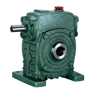
- Weight range: 4–365 kg across the full frame scale
- Reduction ratio: 1:10 to 1:60 (single stage)
- Vertical-input, downward-output shaft arrangement
- Suits overhead motor / downward pump shaft lift station layout
- Oil-bath lubrication; grey or nodular cast iron housing
- Operating temperature: −40°C to +40°C ambient

Environmental Considerations at Outdoor and Below-Grade Lift Station Sites
Lift stations present a more demanding environmental context than most indoor treatment plant installations. Outdoor sites in temperate-climate regions — across the United Kingdom, Northern Europe, Canada, and New Zealand — experience seasonal temperature swings that cycle the gear oil between its cold-start viscosity limit and its upper operating temperature under summer loading. A single speed reducer specified for these sites needs a housing that tolerates freeze-thaw condensation cycles and a breather system that prevents moisture ingress during the pressure equalization that follows cool-down.
In tropical regions — Southeast Asia, Sub-Saharan Africa, Queensland, and similar high-ambient locations — the concern is the reverse: sustained high ambient temperature combined with direct solar loading on an unshaded outdoor enclosure. Gear oil thermal rating becomes the primary sizing constraint. Standard mineral ISO VG 220 oil begins to lose viscosity stability above 80°C oil temperature; a synthetic VG 220 formulation rated to −30°C pour point and 120°C flash point handles both extremes in a single product. Hydrogen sulfide from the wet well collection is present at most lift station sites, making the seal specification and housing paint system important considerations that affect the 10–15-year repaint and overhaul cycles municipalities plan against.
Installation, Commissioning, and First-Run Checks
Correct installation of a single stage right-angle worm-gear speed reducer at a lift station starts with verifying the oil fill level before the first start. WP-series units are typically shipped without gear oil to prevent leakage in transit — the fill port must be charged to the correct level with the appropriate ISO VG grade oil before energizing the motor. A no-oil first start is among the most common causes of premature bronze wheel wear in field installations; the worm-wheel mesh has no hydrodynamic film until oil circulates to the contact zone, and the first 30 seconds of running under load with dry mesh can remove more material than 1,000 hours of correctly lubricated operation.
After oil fill, a hand-rotation check of the input shaft confirms the drive is free and that no transit damage has locked the worm shaft bearings. Following motor connection, a brief no-load run of 15–30 minutes allows oil to circulate and bearing temperatures to stabilize before the pump shaft coupling is engaged. During commissioning, recording the housing surface temperature at motor-rated speed provides the baseline value for all subsequent condition monitoring comparisons. For remote lift stations that are accessed quarterly or less, a simple contactless thermometer reading on every access visit — compared to the commissioning baseline — is among the most reliable early-warning approaches available without continuous telemetry instrumentation.
Low-Maintenance Operation Practices for Remote Lift Stations
The maintenance requirement for a properly sized and installed worm gear speed reducer in screw pump duty is straightforward enough to execute on a quarterly inspection schedule, which suits the access patterns of most municipal lift station maintenance teams. The oil level check — a 30-second procedure via the sight plug or dipstick — is the single most productive item at each inspection visit. It catches both slow external leakage from a seal beginning to fail and internal emulsification from condensation ingress through a blocked breather, both of which show up long before they cause a failure event.
The full oil change interval for mineral VG 220 in continuous pump duty is 2,500–3,000 hours under ambient temperatures below 25°C. This corresponds to approximately 12–15 months of 24/7 operation, or 18–24 months on a typical lift station duty cycle with daytime peak flow periods. For installations in warmer climates or with pump rooms that lack ventilation — common at below-grade lift station sites across Southeast Asian coastal communities — shortening the oil change to 1,500 hours and switching to synthetic ISO VG 220 reduces the risk of film breakdown at elevated oil temperatures. The housing surface area of a correctly frame-sized unit will maintain oil temperature within the lubricant’s rated range at the design ambient condition; if the commissioning baseline surface temperature is more than 15°C above ambient, the thermal rating should be re-evaluated against the actual duty cycle.

Compatible Drive Components for Complete Lift Station Packages
A fully integrated lift station drive assembly requires components that are dimensionally and electrically matched from motor through to pump shaft. Two product families cover the adjacent components and are available from the same source as the WP-series reducers.


Over ons
The manufacturing range covers agricultural gearboxes, worm gear reducers, planetary gear drives, power take-off shafts, hydraulic cylinders, gears, chains, and motors — produced within an ISO 9001:2015 certified quality system. Design and production capacity extends across a wide portfolio of industrial and agricultural gearboxes and assemblies built from ductile iron, cast iron, cast steel, precision cast steel, and cast aluminum. Standard and non-standard mechanical parts — including gears, sprockets, worm gears, pulleys, worms, and shafts — are produced in-house, supporting complete drivetrain supply for municipal infrastructure, treatment plant, and industrial process projects worldwide.
Workshop



Veelgestelde vragen
Redacteur: PXY