
Food & Beverage Industry
A technical reference for engineers and plant managers selecting worm gear single speed reducers for agitators, pumps, conveyors, and separator drives in global dairy processing facilities.
Why Reducer Selection Demands More Attention in Dairy Plants
Dairy processing facilities operate under some of the most demanding conditions in the food industry. Equipment runs continuously across multiple shifts, ambient humidity is elevated from steam cleaning and condensation, and regulatory frameworks in markets from the European Union to North America impose strict hygiene requirements on any component that operates in proximity to raw milk, pasteurized product streams, or finished dairy goods. A single speed reducer positioned in an agitator drive, separator feed pump, or curd processing conveyor is not simply a mechanical power transmission component — it is also a potential contamination control point, a thermal management challenge, and a maintenance cost factor that plant engineers must plan for across a multi-year production lifecycle.
This guide addresses the three variables that most frequently determine whether a given worm gear single speed reducer succeeds or fails in dairy duty: torque rating relative to the actual load profile, hygienic construction features, and duty cycle compatibility. Getting all three right from the specification stage prevents the mid-lifecycle failures that force unplanned shutdowns during peak production periods.

Manufacturing Structure: What Makes a Dairy-Grade Single Speed Reducer Different
The internal architecture of a worm gear single speed reducer used in dairy applications is fundamentally the same as a standard industrial unit — worm shaft meshes with a bronze worm wheel on a perpendicular output shaft, all enclosed in a sealed housing — but the dimensional tolerances, surface finishes, and external geometry are specified to a higher standard than general-purpose models. Tight machining tolerances on bearing bores and shaft fits reduce internal clearances that could otherwise allow condensation to migrate past seals during temperature cycling events common in dairy plants, where equipment shifts between ambient temperatures and heated CIP wash temperatures repeatedly within a single shift.
Housing geometry matters more than many specifiers initially recognize. Flat-topped housings with no upward-facing recesses prevent standing water accumulation after washdowns. Smooth external profiles with minimal blind corners reduce the surface area that requires manual cleaning. For agitator and mixer applications where the reducer is mounted directly above an open product vessel, drip protection around output shaft seals is a design priority rather than a cosmetic preference. Cast iron housings are the standard for most dairy processing installations because of their dimensional stability, resistance to the thermal shock of steam cleaning, and the availability of food-compatible paint systems that seal the porous surface against detergent absorption.
Housing Profile
Precision cast iron or cast aluminum. Smooth external surfaces, sealed filler and drain ports, no upward-facing recesses that trap process water or cleaning fluids.
Worm Shaft
Case-hardened alloy steel, thread-ground. Angular contact or tapered roller bearings manage combined axial and radial loads generated by pump and agitator couplings.
Worm Wheel
Tin-bronze or phosphor-bronze alloy keyed to a steel hub. Bronze wear properties suit the continuous low-speed running typical of dairy agitator and separator drives.
Shaft Sealing
FKM (Viton) double-lip radial seals recommended for dairy duty. Superior detergent and steam resistance compared to standard NBR elastomers used in non-food industrial versions.
Material System: Specification Choices That Affect Dairy Plant Performance
The material selection across each component of a single speed worm gear reducer directly determines its behavior under the specific stress conditions of dairy processing duty. Housing castings in grey cast iron provide good vibration damping — relevant when a reducer is mounted to the structural frame of a continuous stirred-tank reactor or a high-shear homogenizer, both common in fluid dairy processing. Cast aluminum housings are specified for applications where weight is a constraint, such as elevated platforms or portable transfer pump installations, though their lower mass means less thermal buffering during temperature transient events.
The lubricant specification is the material decision with the most immediate food safety implication. In dairy plants operating under HACCP or ISO 22000 frameworks, any lubricant in equipment positioned above or adjacent to open product streams must be H1 registered — meaning it is formulated for incidental food contact. H1-grade synthetic polyalkylene glycol (PAG) or white mineral oil gear lubricants are available for WP series worm reducers and should be specified at the procurement stage rather than treated as an afterthought. Mixing non-food-grade mineral oil with H1 synthetic lubricant during an oil change is a common compliance error that invalidates the H1 status of the entire fill.
| Component | Recommended Material | Dairy-Specific Requirement |
|---|---|---|
| Mieszkania | Grey cast iron (sealed paint system) | Smooth, non-porous exterior resists detergent absorption |
| Worm shaft | Alloy steel, HRC 45–55 case hardened | Long wear life across multi-shift continuous agitator duty |
| Worm wheel | Tin-bronze (CuSn) alloy | Low operating temperature at sustained low output RPM |
| Shaft seals | FKM (Viton) double-lip | Resists CIP alkaline/acid detergents and steam temperatures |
| Lubricant | H1-registered PAG or white mineral oil, ISO VG 220–320 | Incidental food contact compliance under HACCP / ISO 22000 |
| Namiar | Chrome steel tapered roller or deep-groove ball | Handles combined loads from pump coupling and agitator shaft weight |
Torque Rating and Load Profile in Dairy Processing Applications
Understanding the actual torque demand of dairy processing equipment before selecting a single speed reducer is the single most consequential step in the specification process. Torque requirements across dairy plant machinery vary widely and do not always correspond to installed motor power. A cheese vat agitator operating at 10 RPM can demand significantly higher output torque from its reducer than the motor nameplate power suggests, because worm gear speed reduction trades efficiency for high torque multiplication at low output speeds. Specifying based on motor kW alone without calculating the actual required output torque and comparing it against the reducer rated torque at the selected ratio is a frequent source of premature reducer failure.
Dairy applications also impose cyclically varying load profiles. Start-up torque on a thick cream separator or a full-tank agitator can be two to four times running torque, demanding a service factor buffer above the nominal reducer rating. Industry practice for continuous dairy duty recommends service factor SF 1.5 for smooth-loading applications such as thin liquid pumps, SF 2.0 for standard agitators with moderate viscosity product, and SF 2.5 or higher for high-viscosity applications such as butter churns or concentrated whey agitators where product stiffness at cold start imposes heavy shock loading on the transmission.
Thin Liquid Pump
Relatively constant torque load. Service factor SF 1.5 appropriate. Output RPM typically 60–150, suited to reduction ratios of 10:1–25:1.
Standard Agitator
Moderate variable load; product viscosity changes through batch cycle. SF 2.0. Output RPM 20–80; ratios 18:1–60:1 are common.
High-Viscosity Mixer
Butter churn, concentrated whey: cold-start shock loading significant. SF 2.5 minimum. Heavy-duty worm drive gearbox with thermal rating buffer required.
Separator Feed
Continuous, relatively smooth load but long daily hours. Thermal power rating of the single speed reducer must be evaluated for sustained duty, not just peak torque.

Featured Model: EP-WPKA Single Speed Reducer for Dairy Agitator and Conveyor Drives
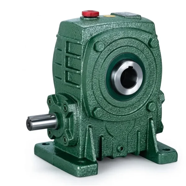
EP-WPKA — 5 to 260 kg Single Speed Reducer
The EP-WPKA covers the weight range from 5 kg to 260 kg across its model size progression, making it applicable to light dairy transfer conveyor drives at the lower end through to heavy-duty agitator installations in large-capacity tank farms at the upper range. The hollow shaft (KA) configuration is particularly useful in dairy plant design because it eliminates the flexible coupling between reducer output shaft and agitator shaft — a common maintenance point and potential lubricant leak source. Direct shaft mounting reduces drivetrain length, simplifies the structural support requirements on tank top frames, and removes misalignment as a potential wear mechanism.
The hardened tooth surface on the worm shaft and the bronze worm wheel combination provides the low-noise, smooth-torque characteristics that dairy process engineers value in agitator applications where turbulent product flow would negatively affect product quality. The WPKA mounting arrangement supports foot-mount, flange-mount, and torque-arm-retained configurations, giving installation engineers the flexibility to adapt the reducer to different tank and frame geometries across a facility.
Duty Cycle and Thermal Rating: The Overlooked Selection Criteria
Many engineers specify a single speed reducer by matching rated output torque to the required load torque and then stop there. In dairy processing, where equipment commonly runs 16–24 hours per day across refrigerated, ambient, and heated process zones, the thermal power rating of the reducer is an equally critical parameter that must be evaluated separately. A worm gear speed reducer that can deliver the required torque on a 30-minute intermittent duty cycle may overheat badly when run continuously for an eight-hour production block, because the heat generated by sliding friction in the worm mesh accumulates in the oil sump faster than it can be dissipated through the housing surface.
Thermal power ratings are typically published in reducer catalogues at a reference ambient temperature, commonly 20°C. Dairy plants frequently operate CIP wash cycles at temperatures that raise the ambient around reducer housings, or conversely operate cold stores where low ambient temperature thickens the lubricant and temporarily increases friction losses on startup. Both extremes require the engineer to verify that the selected single speed gear reducer remains within its thermal envelope across the full operating temperature range of the installation zone. Where thermal rating is borderline, forced cooling fans mounted on the input shaft are available for WP series reducers and extend the continuous duty power capacity by 40–60%.
| Dairy Zone | Typical Ambient Temp. | Duty Cycle | Thermal Management Note |
|---|---|---|---|
| Raw milk reception | 4–10°C | Continuous, pump-driven | Cold-start viscosity spike; allow 15-min warm-up at reduced load |
| Pasteurization area | 30–45°C | Continuous, 16–24 hr/day | Elevated ambient reduces thermal headroom; verify catalogue thermal kW |
| Cheese processing hall | 15–25°C | Batch cycles, 8–12 hr/day | CIP steam exposure between batches; FKM seals mandatory |
| Cold store conveyor | -5 – 4°C | Continuous, 24 hr/day | Specify synthetic low-temperature lubricant; monitor for condensation ingress |
| Butter / cream processing | 18–28°C | Batch, high-viscosity start | High peak torque at cold start; apply SF 2.5 and use high torque worm gearbox rated at upper weight class |
Gear Ratio Selection Across Dairy Processing Equipment Types
The worm gear reduction ratio determines output speed from a given motor input speed. For dairy processing machinery, where output shaft speeds frequently fall well below the 100 RPM mark and sometimes as low as 5–20 RPM for heavy agitator applications, the single reduction worm gear architecture excels because it can achieve high reduction ratios — up to 60:1 or 80:1 — in a single compact stage without multi-stage gear trains that add complexity, cost, and maintenance access requirements. This simplicity is a genuine operational advantage in dairy plant environments where maintenance access is often constrained by stainless steel cladding, CIP pipework, and process vessel geometry.
Speed reducer selection for dairy equipment should begin with the required output shaft RPM, work backward through the chosen gear ratio to determine compatible motor speeds, and then cross-reference against available motor frame sizes to find the configuration that fits the existing installation geometry. Plant managers in markets including the United States, Germany, Australia, and Japan frequently work with local motor suppliers offering IEC or NEMA frame motors; confirming input shaft diameter compatibility between motor and single speed reducer is a check that avoids costly adapter purchases.
| Equipment Type | Output Speed (RPM) | Motor Speed (RPM) | Zakres współczynnika | Recommended WP Model |
|---|---|---|---|---|
| Milk reception pump | 100–150 | 1,400 | 10:1 – 14:1 | WPKS / WPZ |
| Pasteurizer agitator | 40–80 | 1,400 | 18:1 – 35:1 | WPKA / WPDS |
| Cheese vat stirrer | 5–20 | 1,400 | 60:1 – 80:1 | WPDKA / WPKA (large) |
| Butter churn | 10–30 | 1,500 | 50:1 – 60:1 | WPDKA (heavy duty) |
| Cold store conveyor | 20–50 | 1,400 | 28:1 – 60:1 | WPKA / WPKS |

Hygiene Design and CIP Compatibility in Dairy Installations
Clean-in-place (CIP) systems are standard in modern dairy facilities. The reducer itself does not pass through the CIP cycle, but its external surfaces are routinely exposed to high-pressure water jets, alkaline detergent foam, acid rinse solutions, and steam sterilization vapor during scheduled cleaning operations. Housing integrity, seal condition, and external coating adhesion all degrade faster in facilities with aggressive daily CIP schedules than in equivalent non-food industrial installations. Plant engineers should plan reducer seal replacement intervals based on CIP frequency rather than default industrial maintenance schedules.
The physical positioning of the reducer relative to product zones matters for regulatory compliance. A worm speed reducer mounted directly above an open cream separator or cheese hopper creates a drip-down contamination risk if the output shaft seal weeps lubricant. Many dairy equipment OEMs address this by specifying a drip tray or splash guard between the reducer and the product zone, but specifying FKM double-lip seals on all shaft exits and scheduling seal replacement at half the normal interval is a more reliable primary prevention measure. For installations in facilities audited under British Retail Consortium (BRC) or International Featured Standards (IFS) food safety schemes, documentation of lubricant H1 status and seal material specifications may be requested during certification audits.
Customized Single Speed Reducer Configurations for Dairy OEM Equipment Builders
Dairy processing equipment manufacturers operating across global markets — supplying tank systems, agitators, and separator lines to processors in Europe, North America, the Middle East, and Southeast Asia — frequently require customized single speed reducer configurations that deviate from standard catalogue dimensions. Non-standard hollow shaft bore diameters to fit proprietary agitator shaft profiles, stainless steel shaft extensions for corrosion resistance in high-humidity wash-down zones, modified mounting flange hole patterns to match existing equipment frames, and special external paint or powder coat systems compatible with particular detergent chemistries are all modification types routinely handled in WP series production.
OEM bakery and dairy equipment builders also benefit from single speed reducer manufacturer support with documentation packages. CE Declaration of Incorporation, dimensional drawings, material test certificates for bronze wheel alloys, and quality management records under ISO 9001:2015 are all documentation elements that dairy equipment OEMs need to assemble their machine technical files for EU Machinery Directive compliance or equivalent regulatory submissions in other markets. Sourcing reducers from a manufacturer with an established ISO-certified quality system reduces the engineering documentation burden on the OEM during machine certification.
Specify with Confidence
Explore Single Speed Reducers Matched to Dairy Processing Duty
The full WP series single speed reducer range covers input power from 0.12 kW to 15 kW, hollow and solid shaft configurations, and reduction ratios suited to every dairy processing application from thin liquid pump drives to high-viscosity agitators.
Related Products: Drivetrain Components for Dairy Processing Lines
A single speed reducer performs best when it is paired with a correctly sized motor and integrated into a drivetrain sourced from a supplier familiar with food industry requirements. The product categories below complement WP series worm gear single speed reducers across dairy processing applications and are available from the same supply source, simplifying procurement, documentation, and spare parts management.


O nas
The manufacturing programme spans agricultural gearboxes, worm gear reducers, planetary gear drives, power take-off shafts, hydraulic cylinders, gears, chains, and motors — all produced under an ISO 9001:2015 certified quality management system. In-house design and production capabilities extend to industrial and agricultural gearboxes and assemblies in ductile iron, cast iron, cast steel, precision cast steel, and cast aluminum, together with gears, sprockets, worm gears, pulleys, worms, shafts, and both standard and non-standard mechanical parts. This integrated manufacturing scope supports OEM dairy equipment builders, replacement part distributors, and direct end-user customers across global markets with consistent technical documentation and quality assurance.
Warsztat




Często zadawane pytania
What single speed reducer torque rating and service factor should I specify for a continuous dairy agitator running 20 hours per day in a European processing plant?
For continuous dairy agitator duty at 20 hours per day, apply a service factor of SF 2.0 against your calculated running torque to determine the minimum required reducer output torque rating. Verify that the selected single speed gear reducer also meets the thermal power rating at your actual ambient temperature — European dairy halls typically run 15–25°C ambient, which is within standard catalogue conditions. Choose H1-registered lubricant and FKM shaft seals as baseline specifications for any European food industry installation subject to BRC or IFS audit requirements.
How do I find a reliable worm gear single speed reducer supplier for dairy processing equipment in North America who can provide H1 food-grade lubrication and material certifications?
Request confirmation of ISO 9001:2015 certification, ask for the H1 lubricant product datasheet to be supplied with the reducer, and verify that the worm wheel bronze alloy material certificate is available on request. North American dairy equipment operating under USDA or FDA facility oversight benefits from documented H1 lubricant compliance in the equipment maintenance file. A single speed reducer manufacturer with established export experience can typically provide dimensional drawings and material traceability documentation within standard lead times.
What are the disadvantages of a single reduction worm gear reducer when used on a high-viscosity butter churn running at very low output speed in a 24-hour production facility?
The primary disadvantage is lower mechanical efficiency compared to helical alternatives, particularly at ratios above 40:1. At very high reduction ratios, worm gear efficiency can fall below 70%, meaning a significant share of motor input power converts to heat in the gear mesh rather than useful output torque. For a 24-hour butter churn application, cumulative energy cost and thermal management in the reducer housing become meaningful considerations. Mitigating options include specifying a cooling fan on the input shaft, selecting a synthetic H1 gear oil with better high-temperature viscosity retention, and sizing the motor conservatively to keep the reducer operating at moderate load rather than near its thermal ceiling.
When should a dairy equipment OEM in Australia or Southeast Asia consider requesting a customized single speed reducer rather than selecting from a standard catalogue configuration?
Customized single speed reducer variants are worth requesting when your agitator shaft diameter does not match standard hollow output bore sizes, when your tank mounting frame requires a non-standard flange hole circle diameter, when you need a stainless steel shaft extension for operation in high-humidity cold store environments common in Southeast Asian dairy facilities, or when your production line requires a gear ratio between standard catalogue steps. OEM equipment builders supplying to multiple markets benefit from requesting a customized reducer alongside a full dimensional drawing and material certification package that can be included in CE or equivalent technical files without additional supplier documentation requests.
Redaktor: PXY