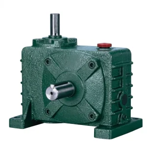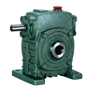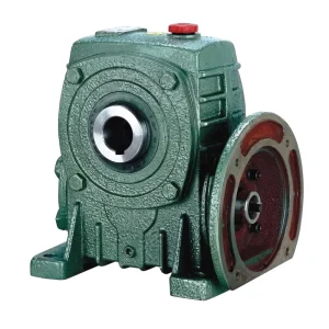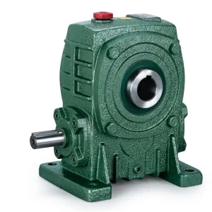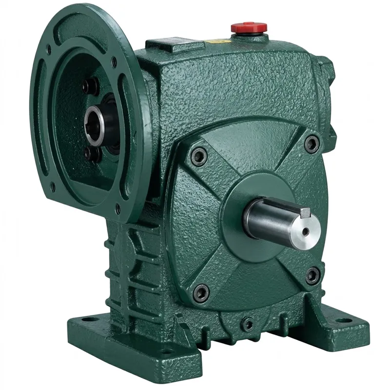
Przekładnia jednobiegowa EP-WPDS o mocy wejściowej od 0,12 do 15 kW
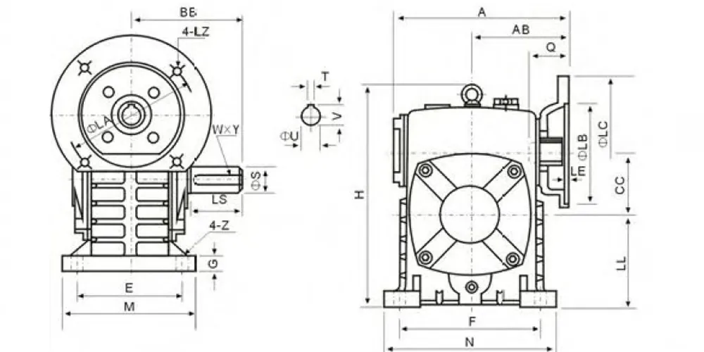
W przeciwieństwie do konwencjonalnych reduktorów ślimakowych z mocowaniem na łapach, w modelu EP-WPDS mocowanie silnika jest zintegrowane bezpośrednio z obudową reduktora za pomocą precyzyjnie obrobionego kołnierza zgodnego z normą IEC (geometria LA × LB × LC × LE) z rozstawem śrub 4-LZ, który pewnie blokuje powierzchnię czołową silnika na wejściu reduktora. Takie rozwiązanie eliminuje problemy z niewspółosiowością związane z oddzielnymi podstawami silnika i elastycznymi sprzęgłami – wał silnika bezpośrednio łączy się z otworem wejściowym ślimaka, tworząc sztywną, kompaktową jednostkę napędową, która jest szybsza w montażu i łatwiejsza do wyosiowania niż tradycyjna konfiguracja z podstawą i sprzęgłem.
Rozmiary ram wahają się od 40 do 250 mm, przy czym każdy rozmiar obsługuje jeden lub więcej poziomów mocy wejściowej, odzwierciedlając moment obrotowy koła ślimakowego w danej ramie. Najmniejszy rozmiar 40 obsługuje moc 0,12 kW; największy, rozmiar 250, obsługuje moce wejściowe 11,0 kW i 15,0 kW. Przełożenia przekładni wahają się od 1/5 do 1/60 w zależności od ramy, obejmując pełen zakres prędkości wyjściowych, przydatnych w pakowaniu, transporcie materiałów, przetwórstwie żywności i ogólnej automatyce przemysłowej. Dostępne są wszystkie sześć konfiguracji kierunku wału (od A do F), co daje projektantom maszyn znaczną elastyczność w sposobie integracji wyjścia reduktora prędkości ślimaka z układem napędzanego urządzenia.
Przekładnia jednobiegowa EP-WPDS — zakres mocy wejściowej od 0,12 do 15 kW
EP-WPDS to silnik z kołnierzem reduktor jednobiegowy Wyposażona w zintegrowany kołnierz IEC po stronie wejściowej, umożliwiający bezpośrednie połączenie czołowe ze standardowym silnikiem elektrycznym bez oddzielnego adaptera lub piasty sprzęgającej. Zaprojektowana do redukcji przekładni ślimakowej kątowej w szerokim zakresie mocy, seria WPDS obejmuje zakresy mocy wejściowej od 0,12 kW do 15 kW w dziesięciu rozmiarach obudowy – co czyni ją jedną z najbardziej wszechstronnych serii sprzężonych z silnikiem. reduktor prędkości jednostopniowy platformy w tej klasie wyjściowej.
Dane techniczne — seria EP-WPDS
Pełne dane wymiarowe i wydajnościowe dla EP-WPDS reduktor jednobiegowy Poniżej wymieniono serie. Wymiary kołnierza silnika (LA, LB, LC, LE, LZ) są zgodne z normami IEC. Wymiary otworu wejściowego (Q, U, T×V) odnoszą się do otworu wału silnika. Wymiary wału wyjściowego (LS, S, W×Y) to parametry wału wyjściowego reduktora. Wszystkie wymiary podano w mm; moc wejściowa w kW; masa w kg. Przewiń poziomo na urządzeniu mobilnym, aby wyświetlić wszystkie kolumny.
| Rozmiar | Moc (kW) | Stosunek | A | AB | nocleg ze śniadaniem | CC | H | LL | M | N | mi | F | G | Z | LA | LB | LC | LE | LZ | Q | U | T×V | LS | S | W×Y | Waga (kg) | ||
|---|---|---|---|---|---|---|---|---|---|---|---|---|---|---|---|---|---|---|---|---|---|---|---|---|---|---|---|---|
| 40 | 0.12 | — | 135 | 75 | 74 | 40 | 141 | 60 | 90 | 100 | 70 | 80 | 13 | 10 | 115 | 95 | 140 | 4 | M8 | 31 | 11 | 4×12,8 | 28 | 14 | 5×3 | 5 | ||
| 50 | 0.18 | — | 151 | 83 | 97 | 50 | 176 | 80 | 120 | 140 | 95 | 110 | 15 | 12 | 115 | 95 | 140 | 4 | M8 | 31 | 11 | 4×12,8 | 40 | 17 | 5×3 | 8 | ||
| 60 | 0.37 | — | 167 | 91 | 112 | 60 | 202 | 90 | 130 | 150 | 105 | 120 | 20 | 12 | 130 | 110 | 160 | 4 | M8 | 33 | 14 | 5×16,3 | 50 | 22 | 7×4 | 11 | ||
| 70 | 0.37 | 1/5 | 200 | 109 | 131 | 70 | 238 | 105 | 150 | 190 | 115 | 150 | 20 | 15 | 130 | 110 | 160 | 4 | M8 | 40 | 14 | 5×16,3 | 60 | 28 | 7×4 | 17 | ||
| 0.75 | 165 | 130 | 200 | 4 | M10 | 42 | 19 | 6×21,8 | ||||||||||||||||||||
| 80 | 0.75 | 1/10 | 202 | 111 | 142 | 80 | 273 | 120 | 170 | 220 | 135 | 180 | 20 | 15 | 165 | 130 | 200 | 4.5 | M10 | 48 | 19 | 6×21,8 | 65 | 32 | 10×4,5 | 22 | ||
| 1.5 | 1/15 1/20 |
165 | 130 | 200 | 4.5 | M10 | 52 | 24 | 8×27,3 | |||||||||||||||||||
| 100 | 1.5 | 1/20 | 225 | 125 | 169 | 100 | 280 | 150 | 190 | 270 | 155 | 220 | 25 | 15 | 165 | 130 | 200 | 4.5 | M10 | 52 | 24 | 8×27,3 | 75 | 38 | 10×4,5 | 38 | ||
| 2.2 | 165 | 130 | 200 | 4.5 | M10 | 52 | 24 | 8×27,3 | ||||||||||||||||||||
| 120 | 2.2 | 1/25 1/30 |
280 | 148 | 190 | 120 | 334 | 180 | 230 | 320 | 180 | 260 | 30 | 18 | 215 | 180 | 250 | 5 | M12 | 63 | 28 | 8×31,3 | 85 | 45 | 12×4,5 | 64 | ||
| 3.0 | 215 | 180 | 250 | 5 | M12 | 63 | 28 | 8×31,3 | ||||||||||||||||||||
| 135 | 3.0 | 1/40 | 333 | 181 | 210 | 135 | 375 | 202 | 215 | 482 | 250 | 350 | 200 | 290 | 30 | 18 | 215 | 180 | 250 | 5 | M12 | 63 | 28 | 8×31,3 | 95 | 55 | 16×6 | 85 |
| 4.0 | 215 | 180 | 250 | 5 | M12 | 63 | 28 | 8×31,3 | ||||||||||||||||||||
| 155 | 5.5 | 1/50 | 375 | 202 | 252 | 155 | 448 | 247 | 235 | 541 | 275 | 390 | 220 | 320 | 35 | 21 | 265 | 230 | 300 | 5 | M12 | 83 | 38 | 10×41,3 | 110 | 60 | 18×7 | 118 |
| 175 | 5.5 | 1/60 | 481 | 262 | 255 | 175 | 600 | 260 | 260 | 310 | 430 | 250 | 350 | 40 | 21 | 265 | 230 | 300 | 5 | M12 | 83 | 38 | 10×41,3 | 110 | 65 | 18×7 | 165 | |
| 7.5 | 265 | 230 | 300 | 5 | M12 | 83 | 38 | 10×41,3 | ||||||||||||||||||||
| 200 | 11.0 | — | 543 | 285 | 319 | 200 | 677 | 290 | 360 | 480 | 290 | 390 | 40 | 24 | 300 | 250 | 350 | 6 | M16 | 114 | 42 | 12×45,3 | 125 | 70 | 20×7,5 | 236 | ||
| 250 | 11.0 | — | 615 | 330 | 385 | 250 | 824 | 350 | 460 | 560 | 380 | 480 | 45 | 28 | 300 | 250 | 350 | 6 | M16 | 114 | 42 | 12×45,3 | 155 | 90 | 25×9 | 396 | ||
| 15.0 | 300 | 250 | 350 | 6 | M16 | 114 | 42 | 12×45,3 |
Wszystkie wymiary podano w mm. Moc wejściowa w kW. Waga w kg. Wiele opcji zasilania ma te same wymiary obudowy, jeśli zostały pokazane. Specyfikacja może zostać potwierdzona przez producenta w przypadku konfiguracji niestandardowych.
Pięć kluczowych zalet przekładni jednobiegowej EP-WPDS
① Zintegrowany kołnierz silnika — nie wymaga sprzęgła
Obrabiana maszynowo powierzchnia wejściowa kołnierza IEC umożliwia bezpośrednie podłączenie standardowego silnika, co skraca czas instalacji i eliminuje procedurę osiowania, wymaganą w przypadku konfiguracji ze sprzęgłem zewnętrznym. Jest to szczególnie korzystne w środowiskach montażu OEM o dużej liczbie zamówień, gdzie reduktor jednobiegowy do linii produkcyjnej maszyn musi być szybkie, powtarzalne i wolne od zmiennych związanych z wyrównywaniem pola.
② Sześć opcji kierunku wału (A–F)
Dzięki konfiguracjom kierunku wału od A do F — obejmującym opcje podwójnego wejścia — system WPDS obsługuje szerszy zakres orientacji układu maszyny niż większość standardowych jednostopniowe przekładnie ślimakowe kątoweEliminuje to potrzebę stosowania kół zębatych zmieniających kierunek lub dodatkowych par kół zębatych kątowych w skomplikowanych ramach maszyn, w których umiejscowienie silnika jest ograniczone.
③ Szeroki zakres mocy wejściowej
Pojedyncza seria produktów obejmująca moc od 0,12 kW do 15 kW pozwala zespołom ds. zaopatrzenia na standaryzację reduktor ślimakowy Platforma obejmuje zarówno małe napędy pomocnicze, jak i maszyny produkcyjne o średniej mocy. Wiele opcji zasilania w ramach tego samego rozmiaru ramy – na przykład 0,75 kW i 1,5 kW, obie pasujące do obudowy rozmiaru 80 – zapewnia dodatkową elastyczność projektantom systemów pracującym z różnymi wariantami maszyn.
④ Kompaktowy układ napędowy
Wyeliminowanie sprzęgła i podstawy podtrzymującej silnik z układu napędowego powoduje znacznie krótszą całkowitą długość osiową w porównaniu z konwencjonalnie montowanym reduktor prędkości przekładni ślimakowej i oddzielny zespół silnika. Ta oszczędność miejsca znajduje bezpośrednie zastosowanie w kompaktowych ramach maszyn – powszechnie stosowanych w urządzeniach pakujących, etykietujących i przenośnikach, gdzie szerokość maszyny jest ograniczona przez standardy szerokości linii produkcyjnej.
⑤ Podstawa z bezpośrednim montażem na stopie
Standardowa podstawa z mocowaniem na łapach i 4-śrubowym układem Z umożliwia przykręcenie WPDS bezpośrednio do ramy maszyny lub płyty bazowej – to samo podejście montażowe, które jest stosowane w przypadku konwencjonalnych reduktorów z mocowaniem na łapach, dzięki czemu istniejące konstrukcje maszyn nie wymagają modyfikacji. W połączeniu z mocowaniem silnika na kołnierzu, WPDS zapewnia kompletne rozwiązanie. reduktor prędkości przekładnia ślimakowa montaż w ramach pojedynczej operacji przykręcania śrub po każdej stronie.
Jak działa przekładnia jednobiegowa WPDS
W swojej strukturze mechanicznej EP-WPDS działa na tej samej zasadzie ślimaka i koła, która jest wspólna dla wszystkich przekładni kątowych. reduktory ślimakowe jednostopniowe: śrubowo-gwintowany wał ślimakowy zazębia się z brązowym kołem ślimakowym, przekształcając wysoką prędkość obrotową wejściową na niższą prędkość wyjściową o wyższym momencie obrotowym przy zmianie kierunku wału o 90°. Przełożenie jest określane przez liczbę zębów koła ślimakowego podzieloną przez skok ślimaka (liczbę zwojów gwintu). Przy 1/5 ślimak ma pięć zwojów, a koło – 25 zębów. Przy 1/60 ślimak z jednym zwojem napędza koło o 60 zębach – wszystko w tej samej podstawowej geometrii obudowy.
Cechą wyróżniającą WPDS jest sposób wprowadzenia wału wejściowego. Zamiast konwencjonalnego wału wejściowego wystającego z obudowy w celu połączenia z oddzielnie zamontowanym silnikiem, WPDS posiada obrobioną maszynowo powierzchnię czołową kołnierza IEC — średnica (wymiar T), rozstaw śrub (4 otwory LZ) i otwór centralny (wymiar Q) są obrobione zgodnie ze standardowymi tolerancjami IEC. Wał wyjściowy silnika przechodzi przez otwór centralny i zazębia się z wałkiem ślimakowym poprzez precyzyjne dopasowanie, a powierzchnia czołowa silnika jest przykręcona bezpośrednio do kołnierza reduktora. Rezultatem jest sztywny, koncentryczny zespół silnik-reduktor, który nie wymaga oddzielnej procedury osiowania i utrzymuje prawidłowe napięcie wstępne łożyska wału ślimakowego, ponieważ ciężar silnika jest przenoszony bezpośrednio na konstrukcję obudowy reduktora, a nie na sprzęgło.
Ta konfiguracja jest szczególnie odpowiednia do zastosowań, w których jednobiegowa przekładnia ślimakowa musi zostać zainstalowany i uruchomiony szybko — jest to powszechny wymóg w zakładach produkujących żywność i napoje, liniach pakowania OEM oraz urządzeniach do przetwarzania produktów farmaceutycznych w regulowanych środowiskach produkcyjnych w Europie, Australii i Ameryce Północnej.
Normy materiałowe i inżynieryjne
Obudowa każdego EP-WPDS reduktor jednobiegowy jest odlewany z wysokiej jakości żeliwa szarego (specyfikacja HT250), dobranego ze względu na połączenie stabilności wymiarowej, tłumienia drgań i obrabialności. Kołnierz silnika – krytyczny wymiar decydujący o dokładności centrowania silnika – jest obrabiany mechanicznie po odlaniu, aby zachować tolerancję luzu roboczego, która gwarantuje, że wał silnika i otwór wejściowy ślimaka pozostają współosiowe w granicach wymaganych dla płynnej i bezwibracyjnej pracy. W przypadku rozmiarów ram od 200 w górę, gdzie masa silnika znacznie wzrasta, rozstaw śrub kołnierza zwiększa się do M16 (w porównaniu z M8/M10/M12 w mniejszych ramach), aby sprostać zwiększonemu obciążeniu wspornika wynikającemu z masy silnika.
Wał ślimakowy wykonany jest ze stali stopowej 20CrMnTi, nawęglanej i utwardzanej powierzchniowo do twardości powierzchni HRC 58–62, z wytrzymałym, ciągliwym rdzeniem zachowanym dzięki kontrolowanej obróbce cieplnej. Szlifowane powierzchnie boczne gwintu ślimaka zapewniają równomierny wzór styku zębów na całej szerokości czołowej brązowego koła ślimakowego. Samo koło ślimakowe jest odlewane odśrodkowo z brązu fosforowego (CuSn10P) — materiału zapewniającego niski współczynnik tarcia ślizgowego, krytyczny w przekładniach ślimakowych, gdzie styk zębów ma charakter ślizgowy, a nie toczny. To połączenie twardego ślimaka i miękkiego koła brązowego sprawia, że koło działa jak element planowego zużycia: można je łatwo sprawdzić i wymienić bez wpływu na stan obudowy lub wału.
Wymiary otworu wejściowego (Q, U, T×V w tabeli specyfikacji) odpowiadają standardowym średnicom wału silnika i serii rowków wpustowych IEC, obejmującym zakres od 11 mm (kołnierz M8, rozmiar 40) do 42 mm (kołnierz M16, rozmiar 250). Zgodność z normami wału silnika IEC oznacza, że EP-WPDS akceptuje silniki dowolnego producenta zgodnego z normami IEC na całym świecie — to znacząca zaleta dla klientów na rynkach, na których wymagane są określone marki silników lub lokalne certyfikaty, w tym silniki z oznaczeniem CE dla instalacji europejskich lub silniki z aprobatą CSA dla kanadyjskich projektów przemysłowych.
Scenariusze zastosowań
Konstrukcja EP-WPDS z bezpośrednim połączeniem silnika z kołnierzem sprawia, że urządzenie to idealnie nadaje się do zastosowań, w których wymagana jest jednocześnie kompaktowa konstrukcja, szybki montaż i zgodność z normą IEC dla silników. Poniższe scenariusze przedstawiają sektory, w których jednostki WPDS są najczęściej stosowane.
Zautomatyzowane linie pakujące
Stacje napełniające, głowice zamykające i obrotowe stoły etykietujące w liniach pakujących w Wielkiej Brytanii i Europie wymagają kompaktowych i łatwych w serwisowaniu urządzeń reduktor jednobiegowy Jednostki montowane na równo z ramą maszyny. WPDS integruje kompletny zespół silnika i reduktora w minimalnej przestrzeni osiowej, a standardowy kołnierz IEC umożliwia wymianę silnika w terenie bez konieczności ponownego ustawiania reduktora — co jest kluczową zaletą w środowiskach produkcyjnych o wysokiej sprawności.
Przenośniki do przetwarzania żywności
Przenośniki taśmowo-płytowe, chłodnice spiralne i taśmy do transportu produktów w australijskich i kanadyjskich zakładach przetwórstwa żywności wykorzystują system WPDS ze względu na jego szczelną obudowę i łatwą konserwację. Bezpośrednie podłączenie silnika za pomocą kołnierza eliminuje odsłonięte elastyczne złącze, które może gromadzić resztki jedzenia w otwartych przestrzeniach przenośnika, upraszczając zarówno czyszczenie, jak i przestrzeganie zasad higieny.
Pomocnicze urządzenia rolnicze
Napędy dozowników nasion, tarcze rozsiewające nawóz i napędy silników obrotowych systemów nawadniających w sprzęcie rolniczym często wykorzystują silnik przekładni ślimakowej Montaż w miejscach, gdzie wymagane są kompaktowe rozmiary i obudowa odporna na warunki atmosferyczne. Uszczelniona konstrukcja WPDS w kąpieli olejowej i podstawa z mocowaniem na stopie wytrzymują wibracje i narażenie na czynniki środowiskowe typowe dla cyklów pracy sprzętu polowego na rynkach rolnych Ameryki Południowej i Azji Południowo-Wschodniej.
Sprzęt farmaceutyczny i laboratoryjny
Naczynia mieszające, napędy reaktorów i pompy dozujące w zakładach farmaceutycznych wymagają jednobiegowa przekładnia ślimakowa który akceptuje precyzyjnie określone silniki IEC (często z wymaganiami ATEX lub dotyczącymi pomieszczeń czystych) bez konieczności stosowania niestandardowych adapterów. Interfejs kołnierzowy WPDS umożliwia montaż tych specjalistycznych silników w tej samej obudowie, co w standardowych zastosowaniach przemysłowych, co upraszcza dokumentację walidacyjną dla obiektów podlegających regulacjom FDA lub EMA.
Maszyny tekstylne i drukarskie
Napędy belek osnowowych, rolki napinające tkaninę i pompy dozujące farbę w zakładach tekstylnych i drukarniach komercyjnych we Francji, Korei Południowej i Azji Południowo-Wschodniej wykorzystują cichą siatkę ślimakową, aby zapewnić płynną, pozbawioną drgań prędkość wyjściową, co zapobiega problemom z jakością produktu. Konfiguracja WPDS z napędem bezpośrednim silnika redukuje również poziom hałasu maszyny w porównaniu z alternatywnymi rozwiązaniami z pasem i sprzęgłem – co jest istotnym czynnikiem w wielozmianowych zakładach włókienniczych.
Napędy bram, zaworów i siłowników
Zautomatyzowane siłowniki bram, napędy trzpieni zaworów i obrotnice pozycjonujące wykorzystują WPDS przy wysokich przełożeniach (1/40–1/60), gdzie opór wsteczny przekładni ślimakowej eliminuje potrzebę stosowania oddzielnego hamulca utrzymującego położenie. W przypadku projektów infrastruktury miejskiej i automatyki zakładów przemysłowych w Brazylii i na Bliskim Wschodzie, ta pasywna blokada położenia bezpośrednio przekłada się na oszczędność kosztów w projektowaniu układu napędowego siłownika.
O naszej działalności produkcyjnej
Dzięki ponad dziesięcioletniemu doświadczeniu w mechanicznych układach przeniesienia napędu, nasz zespół inżynieryjno-produkcyjny zdobył bogate doświadczenie w szerokiej gamie produktów. Projektujemy i produkujemy przekładnie rolnicze, przekładnie ślimakowe, przekładnie planetarne, wały odbioru mocy, cylindry hydrauliczne, koła zębate, łańcuchy i silniki — w całości w naszym własnym zakładzie produkcyjnym, z pełną kontrolą nad materiałami, procesami obróbki i weryfikacją jakości na każdym etapie.
Nasz zakład posiada certyfikat ISO 9001:2015, a produkcja obejmuje szeroki zakres standardowych i niestandardowych przekładni i zespołów z żeliwa sferoidalnego, żeliwa, staliwa, staliwa precyzyjnego i aluminium. Produkujemy koła zębate, koła łańcuchowe, przekładnie ślimakowe, koła pasowe, ślimaki, wały i precyzyjne elementy mechaniczne, zarówno według specyfikacji katalogowych, jak i niestandardowych rysunków OEM. Jako bezpośrednie źródło, a nie pośrednik handlowy, możemy odpowiedzieć na każde zamówienie. dostosowany reduktor jednobiegowy żądania — zmodyfikowane wymiary wału, specjalne powłoki, zmienione wzory montażowe — bez czasu realizacji i kosztów ogólnych związanych z korzystaniem z zewnętrznego łańcucha zaopatrzenia.
Warsztat




Powiązane produkty
System EP-WPDS obsługuje standardowe silniki IEC i pasuje do szerszego systemu napędowego, który dostarczamy z jednego źródła. Połączenie reduktora z dopasowanym silnikiem lub kompatybilną przekładnią z naszego katalogu eliminuje niepewność dotyczącą interfejsu i upraszcza zarządzanie częściami zamiennymi w całym parku maszynowym.
Silniki elektryczne
Nasz silniki elektryczne są produkowane zgodnie z wymiarami ramy IEC i obejmują cały zakres średnic wału i rowków wpustowych, jakie obsługuje seria otworów wejściowych WPDS — od 11 mm przy rozmiarze 40 do 42 mm przy rozmiarze 250. Określenie silnika i silnik przekładni ślimakowej Montaż w naszym zakładzie oznacza, że dopasowanie elementów, wymiary rowków wpustowych i długość wału są weryfikowane przed wysyłką, co eliminuje konieczność prób i błędów, która może wystąpić w przypadku oddzielnego zakupu reduktora i silnika.

Kompletny asortyment przekładni ślimakowych
WPDS jest częścią naszej szerszej serii WPA, WPS, WPX, WPO i NMRV przekładnia ślimakowa portfolio. Jeśli Twoja aplikacja wymaga innej konfiguracji montażu — standardowego montażu na łapach bez kołnierza wejściowego, wyjścia z wałem pustym lub kompaktowego Reduktor ślimakowy NMRV Do bardzo ciasnych przestrzeni — nasza oferta zapewnia odpowiednie dopasowanie. Wszystkie serie wykorzystują to samo brązowe koło i hartowaną konstrukcję ślimaka i są dostępne jako reduktor ślimakowy premium wersje z syntetycznym olejem przekładniowym, zapewniające dłuższe okresy międzyobsługowe w zastosowaniach wymagających wysokiej temperatury lub dużej liczby cykli.

Często zadawane pytania
Redaktor: PXY