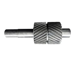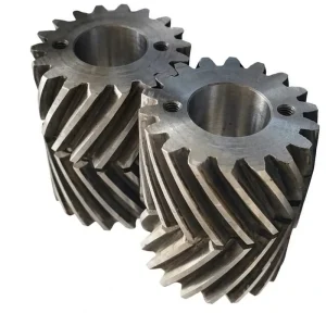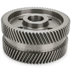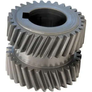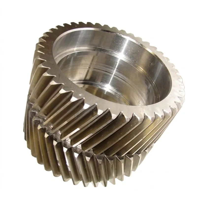
EP-Industrial Alloy Steel Double Helical Gears
El EP-Industrial Alloy Steel Double Helical Gear is a high-performance transmission component engineered for demanding industrial applications. Constructed from durable alloy steel, this round-shaped gear features a double helical tooth form that effectively cancels out axial thrust forces, ensuring smooth operation and reduced bearing load. Designed for heavy-duty machinery, it offers superior torque transmission and stability compared to single helical gears. With a minimum order quantity of just one unit, it provides flexibility for both prototype development and large-scale production. Ideal for use in gearboxes, compressors, and industrial drives where reliability and high load capacity are critical.
EP-Industrial Alloy Steel Double Helical Gears — Heavy-Duty Double Helical Gear for Industrial Power Transmission
The EP-Industrial Alloy Steel Double Helical Gears series is built for the sustained, high-load transmission environments found in heavy industrial machinery — steel mills, mining equipment, cement plants, large compressor drives, and turbine reduction gearboxes. Manufactured from alloy steel with a double tooth form on a round gear body, this double helical gear delivers the defining performance advantage of the double helical design: complete cancellation of axial thrust loads within the gear body itself, combined with a high contact ratio that distributes transmitted torque across multiple tooth pairs simultaneously. The result is a gear with higher effective load capacity, lower vibration, and longer fatigue life than an equivalent single-helix helical gear — without the weight penalty of oversized thrust bearings.
Technical Specifications — EP-Industrial Alloy Steel Double Helical Gears
| Parámetro | Especificación |
|---|---|
| Tipo de engranaje | Double Helical |
| Usage / Application | Industrial |
| Tooth Form | Double (opposing left-hand and right-hand helical sections with centre groove) |
| Material | Alloy Steel (grade specified per application duty: 42CrMo4, 20CrNiMoA, 18CrNiMo7-6 or equivalent) |
| Shape | Round (standard parallel-shaft cylindrical gear body) |
| Minimum Order Quantity | 1 unit (project-based supply supported) |
| Tooth Geometry | Involute profile, helix angle per design specification, pressure angle typically 20° |
| Manufacturing Process | Forging → rough machining → helical gear milling or hobbing → heat treatment → tooth grinding |
| Heat Treatment Options | Carburising and quenching, induction hardening, through-hardening (per grade and application) |
| Customisation | Custom made helical gears produced to customer drawings or samples |
| Certificación de calidad | ISO 9001:2015 quality management system |
What Makes the EP-Industrial Alloy Steel Double Helical Gear the Right Choice for Heavy Industrial Drives?
In large-scale industrial gearboxes — the kind that drive rolling mills, ship propulsion shafts, large fan and compressor units, and mineral processing equipment — gear selection goes far beyond simply matching a module and centre distance to a speed ratio. The gear must survive continuous operation under high mean torques with superimposed shock loads, in environments where thermal cycling, lubricant contamination, and structural deflection of the gearbox housing are all part of normal operating conditions. Under these demands, a single-helix helical gear imposes substantial axial shaft loads that require heavy angular-contact or tapered-roller thrust bearing arrangements — adding weight, cost, and potential failure points to the drivetrain. A double helical gear solves this problem structurally: its two opposing helical tooth sets cancel their axial forces within the gear hub, leaving the shaft bearings to handle only radial and tangential loads.
The EP-Industrial series uses alloy steel throughout — a broad material category that in gear manufacturing typically encompasses chromium-molybdenum grades (42CrMo4, 4140), chromium-nickel-molybdenum grades (20CrNiMoA, 8620), and higher-alloy variants for specific hardness-depth or shock-resistance requirements. The choice of alloy steel over plain carbon steel is deliberate: alloy elements — primarily chromium, nickel, and molybdenum — improve hardenability (allowing uniform hardness through a larger cross-section), improve core toughness at a given surface hardness level, and reduce the susceptibility to fatigue crack initiation at stress concentrations such as tooth root fillets. For a double helical gear running in a continuous industrial drive, these metallurgical properties translate directly into years of additional service life between major overhauls.
Comprensión what a double helical gear is used for in heavy industry helps clarify why the double tooth form — with its characteristic V-groove profile — is standard in large gearbox types used across process industries worldwide. Every major industrial gearbox manufacturer in Germany, Japan, the United States, and the United Kingdom specifies double helical gear designs for their highest-power, highest-speed drive stages. The minimum order quantity of 1 unit reflects the project-based nature of heavy industrial gear procurement, where a single gearbox rebuild or a new installation may require just one matched gear pair — and where that single unit must be manufactured to the same exacting standard as a production batch.
Five Key Advantages of the EP-Industrial Alloy Steel Double Helical Gear
Axial Thrust Elimination — Simpler, Lighter Bearing Arrangements
The double helical gear's opposing helix sections cancel axial forces at the gear hub. Shaft bearings handle only radial and tangential loads, removing the need for heavy thrust-bearing assemblies. In large industrial gearboxes where bearing housings account for a meaningful fraction of total weight and cost, this translates to a structurally and economically leaner drivetrain design.
High Contact Ratio — Superior Torque Distribution
Two helical tooth sets engaging simultaneously produce a total effective contact ratio approximately double that of a comparable single-helix helical gear. This means more tooth surface area carries load at every instant in the mesh cycle — reducing peak tooth stress, extending fatigue life, and lowering the amplitude of transmission error that drives gear noise and structural vibration in heavy machinery foundations.
Alloy Steel Construction — Depth-Hardened for Heavy Load
Alloy steel grades used in the EP-Industrial series respond to heat treatment to produce case-hardened or through-hardened tooth surfaces with controlled hardness depth profiles. This allows the gear designer to specify the surface hardness needed to resist pitting and scuffing on the tooth flank, while maintaining adequate core toughness to survive bending fatigue at the tooth root — a balance that plain carbon steel cannot reliably achieve at large module sizes.
Self-Centering Axial Float — Accommodates Housing Deflection
Because the two helical sections of a double helical gear balance their axial forces, the gear body naturally seeks the axial position of minimum mesh force — it self-centers without requiring precision axial location on the shaft. This self-centering behaviour is particularly valuable in large industrial gearboxes where housing flexure under full-load conditions would otherwise cause systematic lead error in a fixed-position helical gear, leading to uneven load distribution across the face width and accelerated edge loading.
MOQ of 1 — Project-Oriented Supply Flexibility
Industrial double helical gear procurement is rarely a volume-production exercise. Gearbox rebuilds, plant upgrades, and new custom installations typically require one matched gear pair — sometimes produced to a unique module, centre distance, or face width not available from standard catalogues. A minimum order quantity of 1 unit ensures that OEM project engineers and MRO procurement teams can obtain a single manufactured-to-drawing component without the commercial overhead of a production batch minimum.
How Does a Double Helical Gear Work in an Industrial Drive System?
A double helical gear operates on the same involute tooth meshing principle as a standard helical gear — but with two helical tooth sections on the same gear body rather than one. As the gear rotates, the right-hand and left-hand helical sections engage their counterparts on the mating gear simultaneously. Each section generates an axial thrust force, but because the helix angles of the two sections are equal in magnitude and opposite in direction, the axial forces cancel within the gear body. The shaft and its support bearings receive only the radial separating force and the tangential driving force — the components that actually transfer power — without the axial load that demands thrust bearing provision in single-helix designs.
The contact mechanics of a double helical gear also provide a natural self-centering effect under load. If the gear drifts axially away from the mesh equilibrium position, the tooth contact stress on the leading helical section increases while the other decreases — generating a net restoring axial force that pushes the gear back toward equilibrium. This feedback mechanism keeps the double helical gear self-aligned without requiring precision axial shaft positioning, which is a practical advantage in large industrial gearboxes where thermal growth and structural deflection continuously shift shaft positions relative to the gear housing.
In terms of helical gear machining and double helical gear design, the manufacturing sequence for an industrial alloy steel double helical gear typically begins with a rough-turned and rough-bored blank, followed by gear hobbing or milling of the two helical tooth sections with a centre groove between them. The centre groove is a distinctive feature of the double helical gear — it allows the hobbing or milling cutter to run out of the tooth at the centreline, which is mechanically impossible in a true continuous herringbone profile. After hobbing, the blank goes through heat treatment (typically carburising and quenching, or induction hardening for through-hardened grades), and then finish grinding of the tooth flanks to achieve the specified accuracy class. This full sequence — forging or billet cutting, rough machining, gear cutting, heat treatment, gear grinding — is how industrial alloy steel double helical gears are made to the quality levels demanded by process industry users globally.
Helical Gear Material — Alloy Steel in Industrial Double Helical Applications
The term alloy steel covers a broad range of engineering steels, and the choice of specific grade within that range matters significantly for gear performance. In the EP-Industrial series, alloy steel selection follows the duty classification of the application: lower-speed, higher-torque applications favour through-hardened grades such as 42CrMo4 (EN 19 / 4140 equivalent), which develop uniform hardness through large cross-sections and offer good resistance to bending fatigue under high mean stress. Higher-speed applications with contact fatigue as the primary failure mode are better served by case-hardening grades such as 20CrNiMoA (8620 equivalent) or 18CrNiMo7-6, where carburising produces a hard tooth surface (typically 58–62 HRC) over a tough, crack-resistant core.
The round gear shape specified for the EP-Industrial series is the standard form for parallel-shaft double helical gear applications — a solid or hollow cylindrical blank with double helical teeth cut on the outer diameter. The alloy steel blank is forged rather than cut from bar stock wherever the module and face width combination makes the grain-flow alignment of forging beneficial for fatigue life. Forging aligns the internal grain structure with the tooth root geometry, increasing resistance to the bending fatigue crack initiation that is the primary long-term failure mode in large industrial gears running continuously under full load. Steel helical gear procurement for large industrial applications almost always requires material certification traceable to EN 10204 3.1 (mill certificate) or equivalent national standards in the United States (MTR to ASTM A534 or similar), Japan (JIS G4105), or Australia (AS 1444).
The question of which is better, spur or helical gear for heavy industrial drives is settled clearly in favour of helical — and specifically double helical — configurations above a certain power level. The contact-ratio and noise advantages of helical teeth are well documented, and for applications above roughly 500 kW on a single parallel-shaft stage, double helical gear design is the standard approach used by leading parallel shaft gearbox manufacturers worldwide. Worm gear and helical gear comparisons for high-power drives always favour helical geometry for efficiency at large power levels, since worm gear efficiency decreases as the power-to-speed ratio increases.
Double Helical Gear Design — Industrial Context and Comparison with Alternatives
When engineers working on large industrial gearbox projects in Germany, Japan, the United States, Brazil, or Australia assess gear type selection, the double helical gear sits at the top of the performance hierarchy for high-power parallel-shaft stages. The advantages of double helical gear over a spur gear and helical gear pair at equivalent power ratings are well documented in ISO 6336 gear load capacity calculations: higher allowable tooth load per unit face width, lower dynamic load factor due to high contact ratio, and reduced bearing loads due to axial force cancellation.
The debate around double helical vs herringbone gear is largely settled in industrial practice by the manufacturing precision argument: an industrial double helical gear with a centre groove can be tooth-ground to DIN 5 or better after hobbing, while a true herringbone profile cannot be finish-ground and is therefore limited to DIN 7–9 accuracy from hobbing alone. For low-speed, heavily-loaded gearboxes — some large marine propulsion gearboxes, for example — a herringbone gear may be acceptable. But for high-speed industrial drives where transmission error and noise are concerns, the double helical gear with a ground tooth surface is invariably the correct specification. The helical gear factory producing to this standard needs CNC hobbing machines capable of the helix accuracy required for a balanced double helical tooth set, plus gear grinding equipment with post-grind metrology.
The single vs double helical gear comparison for new industrial gearbox designs increasingly favours double helical configurations as power density requirements increase. Where a single-helix helical gear of sufficient width to handle the design torque would generate axial loads exceeding the bearing capacity of a practical housing, a double helical gear of the same face width and module handles the same torque with no net axial load. This is the engineering logic that makes the double helical gear the standard choice in turbine reduction gearboxes, large compressor drives, and rolling mill main drives across industrial facilities in South Korea, the Netherlands, Canada, and the broader global process industry market.
Application Scenarios — Where Industrial Alloy Steel Double Helical Gears Are Deployed
The double helical gear application range in heavy industry is broad but consistently characterised by high power levels, continuous duty, and demanding reliability targets. The following scenarios represent the primary industrial environments where the EP-Industrial Alloy Steel Double Helical Gear delivers measurable advantages over single-helix or spur gear alternatives.
Steel Mill Rolling Drives
The main drives of hot and cold rolling mills represent one of the most demanding gear applications in heavy industry. High continuous torque, periodic shock loading as stock enters the roll gap, and stringent reliability requirements — mill stoppages cost thousands of dollars per minute — all point to double helical gear design as the standard approach. Major rolling mill OEMs in Germany, Japan, and South Korea specify alloy steel double helical gears in their primary and secondary reduction stages universally.
Large Compressor and Fan Drives
Speed-increasing gearboxes fitted between an electric motor and a high-speed centrifugal compressor or process fan routinely use double helical gear stages for their high-speed pinion and wheel. The double helical gear's zero net axial thrust is decisive here: the compressor shaft must be free to carry its own axial aerodynamic load through its dedicated thrust bearing without additional gear-induced axial forces complicating the bearing arrangement. This application is common in petrochemical plants in the Netherlands, the Middle East, and North America.
Cement and Mineral Processing Mills
Large ball mills, SAG mills, and vertical roller mills used in cement production and mineral processing are driven through high-reduction gearboxes where the gear elements operate under sustained high torque, vibration from the grinding process, and dust-laden lubrication conditions. The higher contact ratio of the double helical gear is particularly valuable here — the load distribution advantage reduces sensitivity to the momentary overloads that grinding media impact events impose on the drive train, improving time-between-overhaul intervals in Australian mining operations and South American cement plants.
Marine Propulsion Reduction Gearboxes
Ship propulsion gearboxes reduce turbine or diesel engine speed to propeller shaft speed through high-ratio parallel-shaft gear stages. Double helical gear design is the established standard in naval and commercial marine propulsion gearboxes because it eliminates the axial thrust loads that, in a marine context, would require separate shaft thrust bearing arrangements to prevent gear-induced forces from acting on propeller shaft seals and bearings. The self-centering property of the double helical gear also provides a small but useful tolerance for shaft misalignment that occurs as ship hulls flex under seaway loads.
Power Generation Turbine Gearboxes
Gas turbine and steam turbine reduction gearboxes for power generation operate at very high pitch line velocities — sometimes exceeding 100 m/s — where tooth surface finish and accuracy directly determine efficiency and noise characteristics. The alloy steel double helical gear, ground to DIN 5 or AGMA 12 equivalent accuracy, provides the combination of high-speed capability and thrust-free shaft loading that turbine generator sets require. Industrial facilities in Canada, the UK, and South Korea operating combined-cycle power plants consistently use this gear configuration in their main power turbine reduction train.
Related Products — One-Stop Helical Transmission Supply
We manufacture the full spectrum of helical gear types alongside our double helical gear series — enabling project engineers and MRO procurement teams to source matched gear sets, pinions, and linear rack components from a single helical gear supplier, eliminating tolerance mismatches and simplifying quality documentation.
Engranaje helicoidal
Our single-helix helical gear series covers module 0.5 through module 10, in both right-hand and left-hand configurations, with hobbed and ground variants available across the full module range. For applications where the axial thrust force of a standard helical gear is acceptable — or where a bevel helical configuration serves an intersecting-shaft drive — our helical gear series provides the same alloy steel material and quality-grade options as the double helical series. Custom made helical gears produced to customer-supplied drawings are supported with a minimum order of 1 unit.

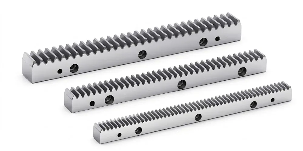
Gear Rack — Helical Rack and Pinion Systems
Large-scale industrial facilities frequently combine rotary double helical gear drives with helical rack and pinion systems for the linear positioning axes of heavy machinery — travelling cranes, gantry structures, large press slides, and heavy-duty positioning tables. Our helical rack and pinion series is designed for direct pairing with our helical gear pinion sets, ensuring consistent helix angle matching and controlled backlash across the full stroke of large industrial linear drives. Helical rack sections are available in steel and alloy steel grades matching the pinion material to ensure uniform wear rates across the mating pair.
About Our Gear Manufacturing Facility
With over a decade of focused experience in precision mechanical power transmission manufacturing, our facility brings together forging, CNC rough and finish machining, gear hobbing and milling, heat treatment, gear grinding, and dimensional metrology under a single roof. Our manufacturing portfolio spans agricultural gearboxes, worm gear reducers, planetary gear drives, power take-off shafts, hydraulic cylinders, gears, chains, and industrial motors — produced across a broad range of base materials including ductile iron, cast iron, cast steel, precision cast steel, and cast aluminium.
The facility operates under ISO 9001:2015 certification, covering material traceability, process control, dimensional inspection, and outgoing quality assurance. We design and manufacture custom gears, sprockets, worm gears, pulleys, shafts, and non-standard mechanical parts to customer-supplied drawings or reverse-engineered samples. The helical gear factory is equipped for both standard catalogue supply and single-unit custom manufacture of large-module alloy steel gears for project-based industrial applications.
Our export teams work directly with procurement engineers, project managers, and gearbox OEM customers in Australia, the United Kingdom, Germany, the Netherlands, South Korea, Canada, Brazil, and across North America — providing technical data sheets, material certifications, gear measurement reports, and customs documentation appropriate to each destination market's import requirements.
Preguntas frecuentes
Editor: PXY