EP-S45C Rak kuggstång — 4 till 8 hål, härdning och anlöpning HB20-25°
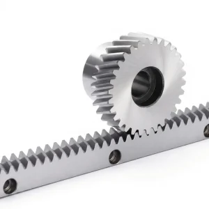
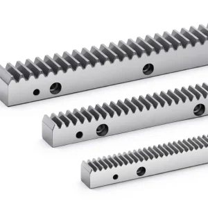
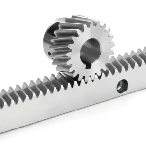
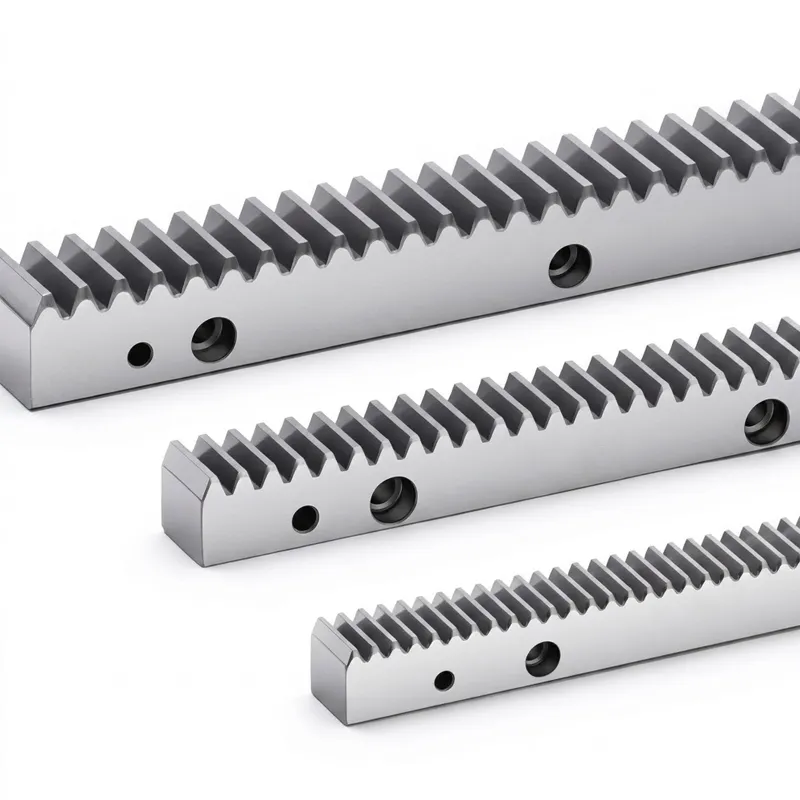
De EP-S45C gear rack series is a robust, cost-effective linear motion solution built from S45C medium-carbon steel and finished to DIN8 international level 7 accuracy. Available across a wide range of modules — from M1.5 through M12 — with rack lengths covering approximately 500 mm and 1000 mm variants, this straight gear rack provides the mechanical foundation for reliable rack and pinion gear drives in everything from machine tool carriages to automated door systems. The quenching and tempering treatment brings bulk hardness to HB20-25°, delivering a balanced combination of surface wear resistance and core toughness that suits prolonged service in industrial environments across Europe, North America, Australia, South Korea, and beyond. Mounting holes (4 or 8 holes depending on length) are machined at precise pitch intervals, and hole-free versions are available on request — just add suffix “N” to the model code, e.g. 661020100-N.
EP-S45C Straight Gear Rack — 4 to 8 Hole, Quenching & Tempering HB20-25°
Technical Specifications — EP-S45C Gear Rack Series (Unit: mm)
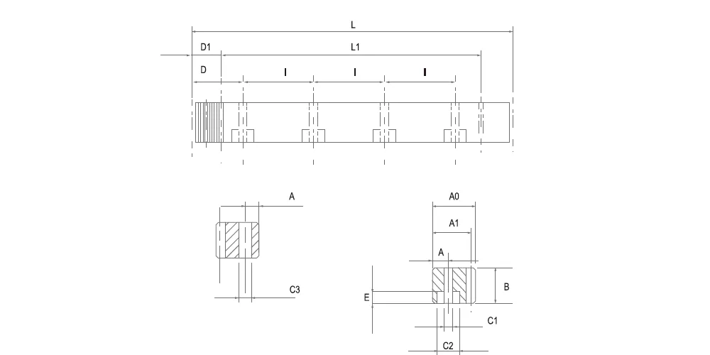
All dimensions listed below are extracted from the production drawing for the EP-S45C gear rack series. The face pitch (Pt) equals Module × π; cumulative pitch error (Fp) is the controlling tolerance parameter at DIN8 level 7. Four-side flat grinding followed by fine cutting ensures consistent face parallelism and tooth accuracy across the full rack length. Note: racks without mounting holes are also available — please indicate suffix "N" when ordering. Other dimensions and materials can be customised to drawing.
| Code | Modul | Pt | Längd (mm) | Tooth No. | B | A0 | A1 | D | Jag | Holes | En | C1 | C2 | E | D1 | I1 | C3 | Fp |
|---|---|---|---|---|---|---|---|---|---|---|---|---|---|---|---|---|---|---|
| 661 010 050 | 1.5 | 4.7123 | 499.51 | 106 | 17 | 17 | 15.5 | 62.44 | 124.88 | 4 | 7 | 6 | 9.5 | 7 | 29 | 441.5 | 5.7 | 0.066 |
| 661 010 100 | 1.5 | 4.7123 | 999.03 | 212 | 17 | 17 | 15.5 | 62.44 | 124.88 | 8 | 7 | 6 | 9.5 | 7 | 29 | 941.0 | 5.7 | 0.074 |
| 661 020 050 | 2 | 6.2831 | 502.65 | 80 | 24 | 24 | 22 | 62.83 | 125.66 | 4 | 8 | 7 | 11 | 7 | 31.3 | 440.1 | 5.7 | 0.066 |
| 661 020 100 | 2 | 6.2831 | 1005.31 | 160 | 24 | 24 | 22 | 62.83 | 125.66 | 8 | 8 | 7 | 11 | 7 | 31.3 | 942.7 | 5.7 | 0.074 |
| 661 030 050 | 3 | 9.4247 | 508.94 | 54 | 29 | 29 | 26 | 63.62 | 127.23 | 4 | 9 | 10 | 15 | 9 | 34.4 | 440.1 | 7.7 | 0.066 |
| 661 030 100 | 3 | 9.4247 | 1017.88 | 108 | 29 | 29 | 26 | 63.62 | 127.23 | 8 | 9 | 10 | 15 | 9 | 34.4 | 949.1 | 7.7 | 0.072 |
| 661 040 050 | 4 | 12.5666 | 502.65 | 40 | 39 | 39 | 35 | 62.83 | 125.66 | 4 | 12 | 10 | 15 | 9 | 37.5 | 427.7 | 7.7 | 0.072 |
| 661 040 100 | 4 | 12.5666 | 1005.31 | 80 | 39 | 39 | 35 | 62.83 | 125.66 | 8 | 12 | 10 | 15 | 9 | 37.5 | 930.3 | 7.7 | 0.078 |
| 661 050 050 | 5 | 15.7079 | 502.65 | 32 | 49 | 39 | 34 | 62.83 | 125.66 | 4 | 12 | 14 | 20 | 13 | 30.1 | 442.4 | 11.7 | 0.072 |
| 661 050 100 | 5 | 15.7079 | 1005.31 | 64 | 49 | 39 | 34 | 62.83 | 125.66 | 8 | 12 | 14 | 20 | 13 | 30.1 | 945.0 | 11.7 | 0.078 |
| 661 060 050 | 6 | 18.8495 | 508.94 | 27 | 59 | 49 | 43 | 63.62 | 127.23 | 4 | 16 | 18 | 26 | 17 | 31.4 | 446.1 | 15.7 | 0.072 |
| 661 080 050 | 8 | 25.1327 | 502.65 | 20 | 79 | 79 | 71 | 62.83 | 125.66 | 4 | 25 | 22 | 33 | 21 | 26.6 | 449.5 | 19.7 | 0.08 |
| 661 100 100 | 10 | 31.4159 | 1005.31 | 32 | 99 | 99 | 89 | 62.83 | 125.66 | 8 | 32 | 33 | 48 | 32 | 125.67 | 754.0 | 19.7 | 0.09 |
| 661 120 100 | 12 | 37.6991 | 1017.88 | 27 | 120 | 120 | 108 | 63.6 | 127.23 | 8 | 40 | 39 | 58 | 38 | 127.23 | 763.4 | 19.7 | 0.09 |
Note: Pe (face pitch) = Module × π; Fp = total cumulative pitch error. Unit: mm. Racks without holes available — add suffix "N" to code, e.g. 661020100-N. Custom dimensions and materials available to drawing.
Working Principle of a Straight Gear Rack
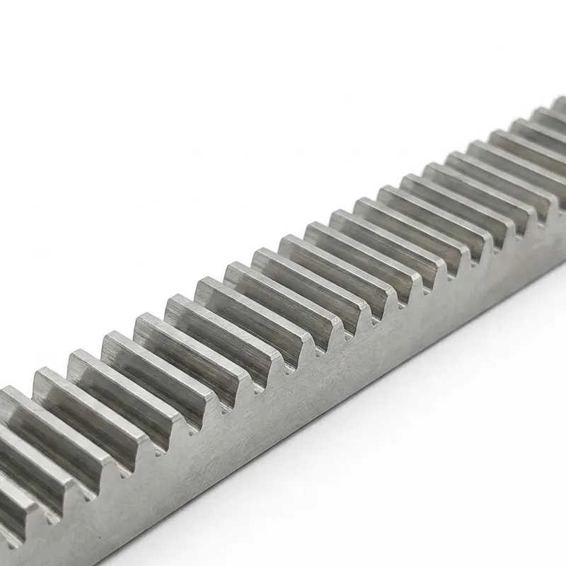
En gear rack is the linearised form of a gear — instead of teeth arranged around a circular pitch diameter, the teeth are distributed along a flat bar. When a rotary pinion engages the rack, every full rotation of the pinion advances the rack by a distance equal to the pinion's circumferential pitch (π × module × number of pinion teeth). This direct relationship between angular input and linear output makes the rack and pinion gear pairing one of the most mechanically transparent drive mechanisms in engineering — no lead screw friction, no belt stretch, and no need to compensate for thermal elongation as you would with a ballscrew on long-travel axes.
The EP-S45C uses a straight gear rack (spur tooth) profile with a standard 20° pressure angle. This means the tooth force is resolved into a radial component (pushing pinion and rack apart) and a tangential component (generating linear thrust). For the gear rack and pinion system designer, this geometry simplifies bearing selection because the radial load on the pinion shaft is predictable and consistent at any rack position. The DIN8 level 7 accuracy class governs the cumulative pitch error (Fp) — meaning the position error accumulated over the full rack length stays within the values tabulated in the specification, giving designers a reliable envelope for worst-case positioning deviation when used as a linear rack and pinion drive.
Quenching and tempering to HB20-25° treats the entire cross-section, not just the surface. This through-hardening approach raises the bulk yield strength and fatigue resistance while keeping the steel machinable for post-treatment fine cutting. The four-side flat grinding operation ensures all mounting faces are parallel and flat within tight tolerances, which matters when multiple gear rack sections are aligned end-to-end on a long machine bed. Pitch continuity across joints is maintained by careful length standardisation, and the pre-drilled mounting holes (4 or 8 depending on length) use a consistent hole pitch pattern that simplifies installation and alignment for engineers worldwide.
Five Key Advantages
S45C Medium-Carbon Steel Construction
S45C is the internationally recognised benchmark material for structural gear rack production, offering a reliable combination of tensile strength, machinability, and response to heat treatment that cheaper mild steels cannot match.
Quenching & Tempering HB20-25°
The full-section thermal treatment raises bulk hardness and fatigue life uniformly, providing long service intervals even in high-cycle duty gear rack applications such as material handling conveyors and machine tool transfer lines.
DIN8 Level 7 Accuracy
The defined Fp (cumulative pitch error) values at each module ensure engineers can predict worst-case positioning error for the full rack length — critical when specifying a spur gear rack for CNC axes or indexing tables.
Wide Module Range M1.5–M12
With modules spanning 1.5 through 12, the EP-S45C series covers everything from light-duty positioning slides to heavy-load gantry drives, eliminating the need to source different rack types from multiple suppliers.
Hole-Free & Custom Rack Options
Specifying suffix "N" delivers a rack without mounting holes for applications using clamp-style fixings. Beyond that, custom gear rack lengths and cross-sections can be supplied to customer drawings, supporting unique machine layouts globally.
Material & Surface Treatment
S45C is a JIS-standard medium-carbon steel equivalent to AISI 1045, DIN C45, or GB 45 steel. Its carbon content of approximately 0.42–0.48% places it in the sweet spot between case-hardening low-carbon steels and high-carbon tool steels — tough enough to resist fracture under shock loading, yet hard enough after quenching and tempering to provide the surface durability required by a working gear rack. The quenching and tempering process applied to the EP-S45C series brings bulk hardness to HB20-25°, which corresponds roughly to Rockwell B87–97 range, delivering significantly better wear resistance than an untreated or normalised rack of the same cross-section.
After heat treatment, each straight gear rack blank undergoes four-side flat grinding to restore dimensional accuracy distorted during the thermal cycle. This step is essential for downstream fine cutting of the tooth form: a flat, parallel reference surface ensures the tooth cutter tracks the intended involute profile without accumulated angular error. The final fine cutting operation brings the rack tooth geometry to DIN8 level 7 accuracy, with the cumulative pitch error (Fp) ranging from 0.066 mm for smaller modules up to 0.09 mm for M10–M12 racks — well within the requirements of most industrial rack and pinion gear drives.
An anti-corrosion protective finish is applied before packaging, preserving the ground surfaces during transit and storage. This is particularly relevant for customers in coastal industrial regions of Australia, the UK, and the Netherlands, where atmospheric humidity can accelerate surface oxidation on unprotected steel. Custom surface treatments — including zinc plating, black oxide, or specialised coatings — are available on request for operating environments with elevated corrosion risk.
Applikationsscenarier
The EP-S45C gear rack is a versatile linear drive component used across a broad spectrum of industrial sectors. Its combination of proven S45C material, heat treatment, and DIN8 accuracy makes it well-suited wherever reliable rotary-to-linear conversion is needed at moderate-to-high load levels. The following scenarios represent typical deployments observed in Europe, the Asia-Pacific region, and the Americas.
🚗 Automated Door & Gate Systems
Industrial sliding doors, high-speed overhead doors, and perimeter security gates routinely use a rack and pinion gear drive for smooth, reliable operation. The EP-S45C straight rack handles the cyclic loading of automated door systems without backlash growth, even after millions of reversals.
🏭 Machine Tool Axis Drives
Horizontal machining centres, boring mills, and heavy-duty planer-type machines use gears rack and pinion drives for both rapid traverse and feed motions. The DIN8 level 7 pitch accuracy keeps positioning error predictable across the full machine table travel.
🔧 Material Handling & Transfer Equipment
Pallet shuttles, floor-mounted transfer cars, and stacker machines in automotive and logistics facilities use linear rack and pinion drives that must withstand heavy payloads and continuous duty cycles. The quenched-and-tempered S45C core handles these impact loads dependably.
🛠 Drill Press & Vertical Boring Equipment
En drill press gear rack must translate quill handle rotation into precise Z-axis feed under cutting force. The fine-cut tooth profile of the EP-S45C provides smooth, backlash-controlled downfeed motion for heavy-duty drill press and radial arm drilling machine applications.
🏢 Construction & Infrastructure Equipment
Rack-and-pinion hoists, rack-driven formwork carriages, and climbing platforms used on construction sites in South Korea, Canada, and Australia demand racks that combine load capacity with reliable engagement across contaminated or partially lubricated contact surfaces — exactly what the HB20-25° treated EP-S45C delivers.
Related Products & One-Stop Supply
Sourcing a complete gear rack and pinion drive system from a single production facility removes the tolerance uncertainty that comes from mixing components made to different standards. We supply the rack, the mating pinion, and the supporting transmission components — so your procurement is streamlined and your system compatibility is guaranteed from the outset.
Plastväxelställ
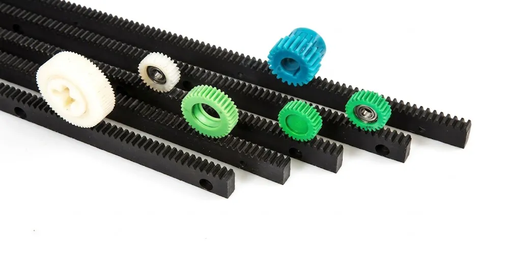
Where corrosion resistance, weight reduction, or lubrication-free operation takes priority over maximum load capacity, our plastic gear rack series offers an interchangeable alternative. Available in identical module ranges to the S45C steel rack, these polymer racks are widely specified in food processing, packaging, and medical automation — sectors where metal contamination risk and washdown requirements make steel unsuitable. The same rack pinion gear standard applies, so interchangeability within a machine family is straightforward.

Helical Gear (Pinion)
For applications where noise level is a constraint, pairing the EP-S45C with a matching helical gear pinion — rather than a standard spur pinion — reduces acoustic emission by distributing tooth mesh load over a longer progressive contact path. Our helical gear series covers modules M1 through M10, in bore-and-keyway or splined hub configurations, ground to matched precision grades. The rack and spur gear combination works well in open-loop systems; adding helical geometry lifts the solution into servo-controlled precision axes without changing the rack.
About Us — Over a Decade of Mechanical Transmission Manufacturing
Our production facility has been dedicated to mechanical power transmission components for more than ten years. Throughout that time, continuous investment in CNC grinding centres, precision inspection equipment, and quality management systems has kept our output consistently aligned with international standards. The facility holds ISO 9001:2015 certification, which governs everything from raw material verification to final dimensional inspection and shipping documentation.
The manufacturing scope is deliberately broad: agricultural gearboxes, worm gear reducers, planetary gear drives, PTO shafts, hydraulic cylinders, precision gears, roller chains, and industrial motors are all produced in-house. We also engineer and manufacture a comprehensive range of gearbox assemblies in ductile iron, grey cast iron, cast steel, investment cast steel, and cast aluminium, alongside sprockets, worm gear sets, pulleys, shafts, and both standard and engineered-to-specification mechanical parts.
De gear rack product line — covering straight, helical, and custom gear rack configurations across module M1.5 through M12 — is fully integrated into this production capability. Customers across the Netherlands, the UK, Australia, Canada, South Korea, Brazil, Colombia, and other global markets benefit from consolidated sourcing, consistent quality traceability, and prompt technical response throughout the order lifecycle.
Vanliga frågor
Redaktör: PXY