
A technical guide to worm gear reducer selection, structural requirements, and material considerations for screw conveyors, stoker feeders, and rotary valves in biomass energy facilities worldwide.
Biomass power plants, district heating boilers, and wood-chip-fired combined heat and power units share a common mechanical challenge at the heart of their fuel handling systems: moving fibrous, irregular, and occasionally damp solid fuel at a controlled rate from storage to the combustion chamber. Screw conveyors, drag chain feeders, rotary pocket valves, and stoker augers are the workhorses of this process, and each of them requires a drive capable of delivering high starting torque, low output speed, and reliable continuous operation at variable load conditions imposed by fuel bulk density changes and bridging events in the fuel hopper.
เอ ตัวลดความเร็วแบบความเร็วเดียว based on the worm gear principle is the dominant drive choice for these applications across biomass facilities in Finland, Sweden, Germany, the UK, Canada, and Australia. The right-angle shaft geometry of the WP-series worm drive fits naturally into the space constraints around screw conveyor troughs and drag chain frames. Its high inherent torque multiplication from a single stage eliminates the need for staged gearing in most sub-15 kW fuel feed drive applications, and its sealed cast-iron housing handles the wood dust, moisture, and biomass debris that would penetrate and corrode open drive arrangements within a single heating season.
What Biomass Fuel Feed Drives Actually Demand
Wood chips, pellets, and agricultural residue fuels impose mechanical loads on their conveyor drives that differ significantly from those found in clean-material processing. Bulk density varies with moisture content — dried pellets may run at 650 kg/m³ while wet green chips fall below 300 kg/m³ — and a single screw conveyor must handle both conditions from the same drive without stalling. Bridging in hoppers creates sudden torque spikes when a plug of compacted fuel collapses onto the moving screw, and these spikes can reach three to five times the normal running torque in uncontrolled feeding systems.
Stoker feeders pushing fuel directly into a combustion grate or retort burner face the additional thermal environment of the furnace front plate, where radiated heat reaches 60–80°C at the drive end of the screw. A ตัวลดความเร็วแบบความเร็วเดียว mounted at the cold end of the feeder shaft must tolerate this ambient temperature without lubricant breakdown or seal extrusion while maintaining the slow, steady output speed — typically 5 to 30 rpm at the screw shaft — that gives the burner controller accurate fuel dosing authority over the combustion process.

Manufacturing Structure of WP-Series Single Speed Reducers
The WP-series ตัวลดความเร็วแบบความเร็วเดียว is built around an integral one-piece housing that is bored, faced, and drilled on a single machining setup. This single-datum production process holds the center distance between the worm shaft and worm wheel shaft to a repeatable tolerance that governs backlash, contact ratio, and the oil film geometry in the mesh zone. In biomass handling applications where torque reversals from screw bridging events repeatedly load and unload the tooth faces, consistent backlash across production batches ensures predictable tooth impact behavior that the product designer can account for in fatigue life calculations.
The worm shaft is produced from chromium-alloy steel bar — 20CrMnTi or 40Cr grade depending on frame size — thread-hobbed and then cylindrically ground after case hardening to 58–62 HRC. Post-heat-treatment grinding is the process step that distinguishes a long-life worm from a short-life one in arduous biomass duty: it restores the lead accuracy and surface finish that heat treatment distorts, and the resulting smooth mating surface across the worm thread flank is what allows the hydrodynamic lubricant film to form reliably at the very low sliding speeds found in 30:1 and 40:1 ratio drives used on slow stoker augers.
Worm wheel rims are centrifugally cast in phosphor bronze and then finish-machined, with the tooth form generated by a hob matched to the worm geometric parameters. The finished gear pair is assembled into the housing with tapered roller bearings preloaded against the worm shaft thrust, end covers fitted with compressed gaskets and filled with the specified oil grade, and the complete unit pressure-tested before leaving the production line. Leak-free operation from day one matters in biomass plants where oil contamination of fuel can trigger compliance issues at facilities operating under renewable energy certification schemes in Germany, Sweden, and the UK.
Material System for Biomass Drive Environments
Housing — Grey Iron
HT200 grey cast iron provides excellent vibration damping at the mounting interface between the gearbox foot and the conveyor trough frame, reducing structure-borne noise transmission in indoor boiler halls. Its high internal damping capacity absorbs the torque spikes from fuel bridging events without the resonance amplification that fabricated steel housings can exhibit.
Worm — Case-Hardened Steel
20CrMnTi or 40Cr steel, carburized to 0.8–1.2 mm case depth and ground after hardening to 58–62 HRC. The hard case resists the Hertzian contact fatigue that repeated torque reversals create at the worm-bronze interface; the tough core absorbs impact energy without brittle fracture during bridging-induced shock loads.
Worm Wheel — Phosphor Bronze
ZCuSn10Pb1 phosphor bronze, centrifugally cast for a dense, pore-free outer layer. Bronze yields locally when torque spikes from bridging fuel exceed the tooth surface strength, absorbing energy without fracturing. This compliant behavior distributes wear across the tooth face rather than concentrating it at a stress riser, extending the wheel service life between overhauls.
Seals and Bearings
Double-lip NBR oil seals at all shaft exits prevent wood dust ingress into the oil bath. Tapered roller bearings on the worm shaft manage the combined radial and axial loads from worm thrust. All bearing and seal sets are replaceable in the field using standard hand tools — an important consideration for biomass plant maintenance staff without specialist gearbox training.
Drive Type Comparison for Biomass Fuel Feed Equipment
| Selection Criterion | Single Stage Worm Reducer | Helical-Bevel Gearmotor | Chain and Sprocket |
|---|---|---|---|
| Output speed range (single stage) | 10:1 – 60:1 ratio | 5:1 – 30:1 typical | 2:1 – 6:1 per stage |
| Torque spike absorption | Bronze wheel yields, absorbs impulse | Steel-to-steel — harder impact | Chain stretch absorbs some load |
| Dust and debris ingress | Sealed cast-iron housing | Sealed housing | Open — dust packs into rollers |
| Right-angle shaft layout | Native geometry | Bevel stage required | Parallel shafts only |
| Self-locking on shutdown | Yes — high-ratio units | No | No |
| Maintenance in dusty environments | Oil change interval only | Oil change + housing wipe-down | Chain lubrication and tension adjustment |
| Oil contamination risk to fuel | Low — sealed sump | Low — sealed sump | High — lubricant applied directly |
Featured Specification: EP-WPDKA Single Speed Reducer
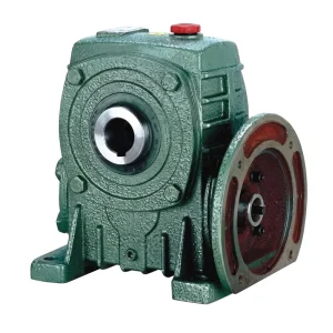
เดอะ EP-WPDKA เกียร์ทดรอบความเร็วเดียว is a hollow-shaft, foot-mounted worm gear drive covering load capacities from 5 to 350 kg with a vertically oriented output shaft. This configuration makes it the natural choice for vertical screw feeders and rotary valve drives in biomass storage silos where the feeder auger descends vertically into a below-floor conveying channel. The hollow output bore allows the screw feeder shaft to pass directly through the reducer without a separate shaft coupling, eliminating one potential misalignment point in a drive that is subjected to the eccentric loads that biomass bridging and flow variation impose on the feeder shaft during normal operation at plants in Germany, Canada, and Scandinavia.
| พารามิเตอร์ | ข้อกำหนด |
|---|---|
| Load Capacity | 5 – 350 กก. |
| การกำหนดค่าเอาต์พุต | Hollow shaft, vertical orientation |
| Ratio Options | 10 / 15 / 20 / 25 / 30 / 40 / 50 / 60 |
| Max Input Speed | 1500 r/min |
| วัสดุสำหรับที่อยู่อาศัย | Cast iron, foot mount |
| Input Type | Hollow shaft input (WPDKA type) |
Screw Conveyor, Stoker Feeder, and Rotary Valve: How Drive Requirements Differ
Three distinct equipment types form the core of biomass fuel feed systems, and each places a somewhat different demand on the ตัวลดความเร็วแบบความเร็วเดียว that drives it. Screw conveyors moving wood chips horizontally from the day bin to the boiler front require moderate starting torque — typically 150 to 200 percent of running torque — and output speeds in the 20 to 60 rpm range. The ตัวลดความเร็วแบบขั้นเดียว at a 20:1 or 25:1 ratio off a standard 4-pole motor delivers this cleanly and allows the plant control system to regulate fuel feed rate by varying the motor duty cycle or, where a variable-frequency drive is used, by adjusting motor frequency without the speed range limitations that high-ratio drives introduce at very low frequencies.
Stoker feeders pushing fuel directly into a retort or grate burner operate at much slower output speeds — 2 to 10 rpm is common — and face the highest instantaneous torque demand of any fuel feed component. A 40:1 or 60:1 ratio เกียร์ทดรอบหนอนความเร็วเดียว is the standard selection for retort stoker drives in UK and Irish district heating boilers, because the high reduction ratio generates the torque multiplication needed to push compacted pellets or damp chips against the fuel pressure in the retort without a secondary reduction stage. The self-locking tendency of high-ratio worm meshes also prevents fuel pressure in the retort from back-driving the screw when the motor is stopped, acting as a passive check valve against reverse fuel flow.
Rotary pocket valves — the air-tight metering devices that transfer fuel between atmospheric and pressurized zones in gasifier systems and pneumatic transport lines — require steady, low-torque drives at very consistent speeds, typically 5 to 20 rpm. These drives must not create pulsating torque that varies rotor speed and disrupts the metering accuracy. Worm gear drives are well suited here because their sliding-contact mesh geometry generates smoother torque transmission than spur or straight bevel gear meshes, and their inherent slight compliance absorbs the momentary load spikes when pocket edges contact oversized fuel particles without transmitting those spikes to the rotor shaft as speed variations.

Operating in Wood Dust and High-Humidity Environments
Wood chip and pellet handling generates persistent airborne dust that settles on gearbox housings, penetrates through seal lips worn by shaft runout, and accumulates in the gap between shaft and housing bore. In a sealed ตัวลดความเร็วแบบความเร็วเดียว housing, the internal oil bath is protected from this environment by the double-lip seals at shaft exits. The outer lip excludes dust and debris; the inner lip retains oil. A grease-packed cavity between the two lips provides an additional barrier and extends the period before fine wood particles work their way through the outer lip during sustained operation at dusty storage and transfer points.
Moisture from green fuel and from pressure-washing of plant floors presents a related problem. Wood chips at 40–50% moisture content release water vapor into the immediate environment of the feeder drive, and this vapor condenses on the cooler metal surfaces of the gearbox housing during overnight plant shutdowns. Condensate that enters the oil bath through a deteriorated seal emulsifies the lubricant and destroys the hydrodynamic film that protects the bronze tooth face. Replacing a failed worm wheel in a biomass plant in Sweden or Finland — where ambient winter temperatures accelerate condensate formation — requires draining the housing, pulling the end cover, extracting the worm wheel, pressing the new bronze rim onto the hub, and reassembling with fresh oil. This is a half-day task; avoiding it by maintaining seal integrity and using a silica-gel breather at the oil filler is a substantially better outcome.
Housing surfaces at biomass plants in high-humidity climates should receive a two-coat protection system — epoxy primer followed by a polyurethane finish — applied over a blast-cleaned iron surface. This system resists the combination of wood acid, moisture, and sawdust abrasion that removes single-coat oil-based finishes within one operating season at facilities in the Pacific Northwest of Canada, coastal Norway, and the wetter regions of the British Isles.
Lubrication Selection and Service Intervals
เดอะ ตัวลดความเร็วแบบความเร็วเดียว used in biomass feed drives operates in the boundary and mixed lubrication regimes at very low output speeds. At 5 to 20 rpm worm wheel speed with a 40:1 ratio drive, the worm shaft is turning at only 200 to 800 rpm — low enough that hydrodynamic pressure at the worm-bronze contact interface depends heavily on the oil viscosity-pressure coefficient and the tooth surface finish quality. ISO VG 220 or VG 320 mineral gear oil is appropriate for drives in temperate-climate biomass plants operating between 5°C and 40°C ambient. For drives adjacent to furnace fronts where sustained ambient temperatures exceed 50°C, ISO VG 460 or a synthetic ISO VG 220 polyalphaolefin maintains adequate viscosity at the elevated sump temperature without excessive carbon deposit formation on the worm shaft surface.
Service intervals follow the operating temperature and duty cycle. At continuous duty in a 30°C ambient environment, a mineral oil change at 3,000 to 4,000 hours is the standard practice for WP-series worm drives. A first oil change at 200–300 hours removes bronze and steel particles generated during the initial break-in wear phase — these metallic fines act as abrasives if left in the sump — and establishes the baseline oil cleanliness that subsequent sample analysis compares against. Biomass plant maintenance programs in Germany and Austria routinely include gearbox oil sampling as part of seasonal inspections, using the metal content of the sample as an early indicator of abnormal wear progression before a tooth failure becomes imminent.

Compatible Components for Complete Biomass Drive Systems
A reliable biomass fuel feed drive pairs the right ตัวลดความเร็วแบบความเร็วเดียว with a matched motor and, where extended ratios or higher torque are needed, a full-range worm gearbox. Sourcing all three components from the same manufacturing family eliminates interface incompatibilities and simplifies spare-parts procurement for facilities in remote forestry regions in Canada, Sweden, and Finland where lead times on non-stocked components can affect plant availability.


เกี่ยวกับผู้ผลิต
The manufacturing range covers agricultural gearboxes, worm gear reducers, planetary gear drives, power take-off shafts, hydraulic cylinders, gears, chains, and motors — a breadth of mechanical power transmission products that serves both industrial and agricultural end-markets across more than 60 countries. The production facility operates under ISO 9001:2015 quality certification, with traceability from raw material receipt through in-process inspection, heat treatment verification, and final functional testing.
Casting in ductile iron, grey cast iron, cast steel, precision cast steel, and cast aluminum is carried out in-house alongside gear hobbing, grinding, induction and carburizing heat treatment, and assembly with leak and load testing. Standard and non-standard gears, sprockets, worm gears, pulleys, shafts, and custom mechanical sub-assemblies are produced from the same tooling infrastructure, supporting both volume OEM supply programs and low-volume custom requirements for specialized biomass equipment manufacturers.
เวิร์คช็อป




คำถามที่พบบ่อย
บรรณาธิการ: PXY