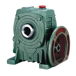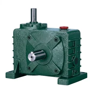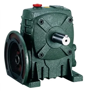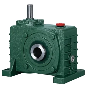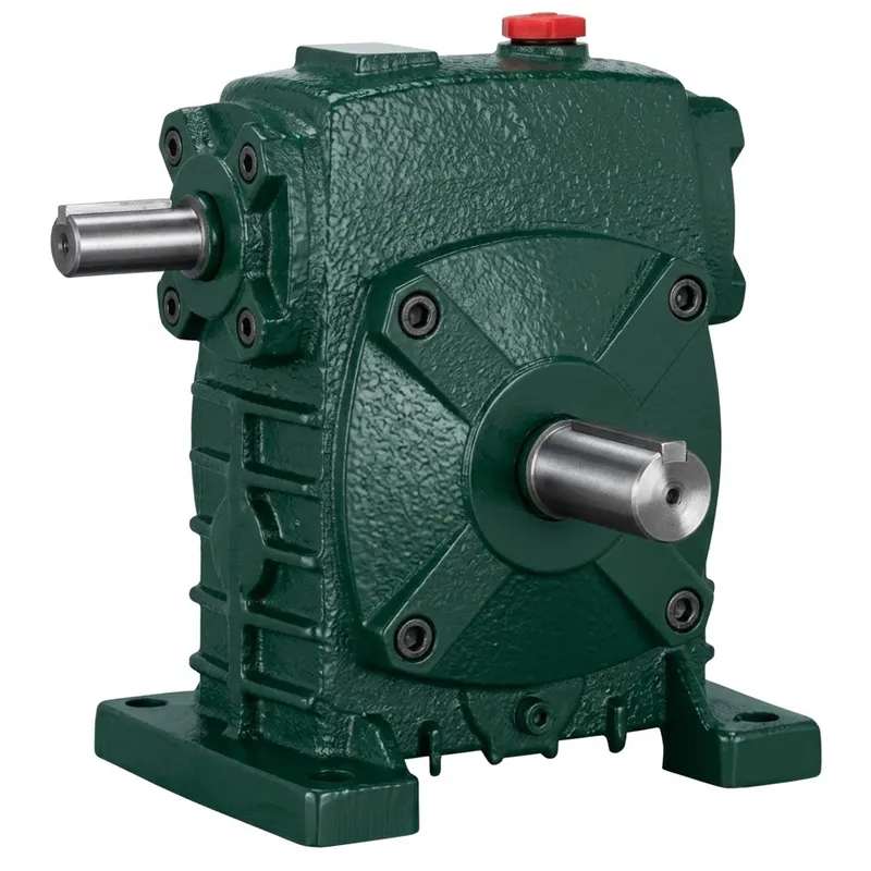
EP-WPS เกียร์ทดรอบความเร็วเดียว ความจุของน้ำมัน 0.3–18 ลิตร
The EP-WPS series is a heavy-duty, single speed worm gear reducer designed around a hardened alloy-steel worm shaft meshing with a phosphor-bronze worm wheel. This pairing delivers quiet, vibration-dampened operation at output speeds determined by the selected worm gear reduction ratio — from a brisk 1/5 step for mixer and agitator duty all the way to a deep 1/60 reduction for slow-speed conveyors and indexing tables. The oil capacity scale — 0.3 L on the compact size-40 up to 18 L on the size-250 — reflects the thermal management engineered into each frame, ensuring that lubrication film integrity is maintained across an 8–10 hour production shift without overheating.
Unlike a double-stage gearbox, the single reduction architecture keeps the mechanical path short. Shorter paths mean fewer bearing loads, less cumulative backlash, and a more predictable single speed reducer transmission output — attributes that matter in feedback-controlled servo systems and in any process where positional accuracy accumulates error over repeated cycles.
Frame sizes 40, 50, 60, 70, 80, 100, 120, 135, 147, 155, 175, 200, and 250 are stocked as standard. Each size is available in all five shaft directions (A–E), and the bolt-pattern and shaft diameters within each frame remain consistent across ratios, so upgrading from a 1/20 to a 1/30 ratio involves swapping the internal gear set rather than redesigning the machine interface.
Industrial Worm Gear Transmission
EP-WPS 0.3–18L Oil Capacity
ตัวลดความเร็วแบบความเร็วเดียว
Precision-engineered ตัวลดความเร็วแบบความเร็วเดียว with right-angle worm drive — built for continuous-duty industrial and agricultural applications across global markets.
ข้อกำหนดทางเทคนิค
WPS Series — Complete Dimensional & Capacity Data (all dimensions in mm, oil in litres, weight in kg)
| ขนาด | อัตราส่วน | เอ | เอบี | บี | BB | ซีซี | ชม | แอลแอล | เอ็ม | เอ็น | อี | เอฟ | จี | ซ | อินพุต HS | Input U | ที×วี | Output LS | เอาต์พุต S | ว×ย | น้ำหนัก (กก.) | น้ำมัน (ลิตร) |
|---|---|---|---|---|---|---|---|---|---|---|---|---|---|---|---|---|---|---|---|---|---|---|
| 40 | — | 143 | 87 | 114 | 74 | 40 | 141 | 60 | 90 | 100 | 70 | 80 | 13 | 10 | 25 | 12 | 4×2.5 | 28 | 14 | 5×3 | 4 | 0.30 |
| 50 | — | 175 | 108 | 150 | 97 | 50 | 180 | 80 | 120 | 140 | 95 | 110 | 15 | 12 | 30 | 12 | 4×2.5 | 40 | 17 | 5×3 | 7 | 0.45 |
| 60 | 1/5 | 198 | 120 | 168 | 112 | 60 | 207 | 90 | 130 | 150 | 105 | 120 | 20 | 12 | 40 | 15 | 5×3 | 50 | 22 | 7×4 | 10 | 0.55 |
| 70 | 1/10 | 231 | 140 | 194 | 131 | 70 | 238 | 105 | 150 | 190 | 115 | 150 | 20 | 15 | 40 | 18 | 5×3 | 60 | 28 | 7×4 | 15 | 0.80 |
| 80 | 1/15 | 261 | 160 | 214 | 142 | 80 | 273 | 120 | 170 | 220 | 135 | 180 | 20 | 15 | 50 | 22 | 7×4 | 65 | 32 | 10×4.5 | 20 | 1.10 |
| 100 | 1/20 | 322 | 190 | 254 | 169 | 100 | 334 | 150 | 190 | 270 | 155 | 220 | 25 | 15 | 50 | 25 | 7×4 | 75 | 38 | 10×4.5 | 35 | 2.90 |
| 120 | 1/25 | 371 | 219 | 282 | 190 | 120 | 423 | 180 | 230 | 320 | 180 | 260 | 30 | 18 | 65 | 30 | 7×4 | 85 | 45 | 12×4.5 | 60 | 4.40 |
| 135 | 1/30 | 422 | 249 | 317 | 210 | 135 | 482 | 215 | 250 | 350 | 200 | 290 | 30 | 18 | 75 | 35 | 10×4.5 | 95 | 55 | 16×6 | 80 | 6.20 |
| 147 | 1/40 | 432 | 256 | 320 | 210 | 147 | 460 | 203 | 250 | 350 | 200 | 280 | 32 | 18 | 75 | 35 | 10×4.5 | 95 | 55 | 10×6 | 98 | 3.70 |
| 155 | 1/50 | 495 | 295 | 382 | 252 | 155 | 541 | 235 | 275 | 390 | 220 | 320 | 21 | 21 | 85 | 40 | 12×5 | 110 | 60 | 18×7 | 110 | 6.50 |
| 175 | 1/60 | 534 | 314 | 388 | 255 | 175 | 600 | 260 | 310 | 430 | 250 | 350 | 40 | 21 | 85 | 45 | 14×5.5 | 110 | 65 | 18×7 | 150 | 8.00 |
| 200 | — | 580 | 342 | 456 | 319 | 200 | 677 | 290 | 360 | 480 | 290 | 390 | 40 | 24 | 95 | 50 | 14×5.5 | 125 | 70 | 20×7.5 | 215 | 9.30 |
| 250 | — | 703 | 420 | 552 | 385 | 250 | 824 | 350 | 460 | 560 | 380 | 480 | 45 | 28 | 110 | 60 | 18×7 | 155 | 90 | 25×9 | 360 | 18.0 |
ข้อดีหลัก 5 ประการของผลิตภัณฑ์
Why engineers specify the WPS ตัวลดความเร็วแบบความเร็วเดียว
① Wide Speed Ratio Coverage
Ratio steps from 1/5 to 1/60 in a ตัวลดความเร็วแบบความเร็วเดียว, covering the broadest range of output speed requirements without additional staging. Suitable for conveyors, agitators, and packaging lines where precise single stage speed reduction defines process quality.
② Five Configurable Shaft Directions
Output shaft orientation A through E lets installation engineers adapt the same unit to horizontal, vertical, or perpendicular drive arrangements without redesigning the machine frame. This flexibility dramatically reduces lead time on custom เกียร์ทดรอบหนอนความเร็วเดียว projects.
③ Compact Right-Angle Footprint
The 90° input-to-output configuration inherent in a single stage right-angle worm-gear speed reducer allows engineers to tuck the drivetrain of the ตัวลดความเร็วแบบความเร็วเดียว into tight machine cavities. Frame sizes 40 through 250 cover torque demands from sub-kilowatt drives to heavy-duty industrial lines in one product family.
④ Self-Locking at High Ratios
At reduction ratios above 1/20, worm gear geometry provides natural back-drive prevention — a property no spur or helical stage can match. This makes the WPS ตัวลดความเร็วแบบความเร็วเดียว the first choice for hoist, gate, and positioning applications where holding position under load is a safety requirement.
⑤ ISO 9001:2015 Manufacturing
Every unit leaves the factory under a certified quality management system with documented inspection records. Dimensional accuracy and surface finish are verified at multiple stages, ensuring that replacement units from our range slot directly into existing mounts without additional machining — critical for OEM and aftermarket ระบบเกียร์ทดกำลังความเร็วเดียว projects.
วิธีการทำงานของเกียร์ทดรอบความเร็วเดียว
At its core, the WPS ตัวลดความเร็วแบบความเร็วเดียว operates on the worm-and-wheel principle: a hardened steel worm shaft — aligned along the input axis — turns against a bronze worm wheel mounted on the output shaft at exactly 90° to the input. Because the worm thread is helical, each revolution of the input shaft advances the wheel by only one tooth pitch, generating the high reduction ratio that makes this class of ตัวลดความเร็วแบบเฟืองตัวหนอน so valuable for slow-speed, high-torque applications.
The single stage right-angle worm-gear speed reducer internal process unfolds in three mechanical steps. First, the motor-coupled input shaft spins the worm at rated motor speed — typically 1,400–1,500 rpm for a 4-pole motor. Second, the thread engagement transfers rotational energy to the worm wheel, simultaneously performing speed reduction and torque multiplication. Third, the output shaft — supported by taper roller bearings on both ends — delivers reduced-speed, high-torque rotation to the driven machine element. The entire sequence occurs within the sealed, oil-filled housing of the ตัวลดความเร็วแบบความเร็วเดียว, with splash lubrication reaching all mesh surfaces continuously.
The geometry also explains the natural self-locking behaviour at high ratios: when the lead angle of the worm falls below the friction angle of the mesh, back-driving the wheel into the worm becomes impossible without a separate brake. This intrinsic property, absent in other ตัวลดความเร็วแบบความเร็วเดียว designs and planetary stages, makes the WPS the preferred choice for hoist, valve, and gate applications across industrial markets from the United States to the EU.

วัสดุและการก่อสร้าง
Material selection in the WPS ตัวลดความเร็วแบบความเร็วเดียว reflects decades of field experience with ตัวลดความเร็วแบบเฟืองตัวหนอน systems across food processing, mining, and general manufacturing environments. The housing is produced in grey cast iron (GG25 equivalent) for most standard sizes, with ductile iron and cast steel options available for shock-loaded or high-cycle applications. Cast iron provides excellent damping of gear-mesh vibration, which extends bearing life and reduces radiated noise compared to fabricated steel housings.
The worm shaft is forged from 20CrMnTi alloy steel, carburised and case-hardened to 58–62 HRC, then ground to h6 tolerance on the shaft journals. This surface integrity is what allows the worm thread flanks to maintain lubricant film under the sliding-contact conditions inherent in ตัวลดความเร็วแบบความเร็วเดียว operation, conditions that would rapidly score a through-hardened shaft. The worm wheel rim is centrifugally cast in phosphor-bronze (CuSn12), chosen for its combination of anti-seizure properties, good conformability to minor worm misalignment, and resistance to the adhesive wear that limits steel-on-steel worm pairs.
Bearings are deep-groove ball bearings on the worm input shaft and taper roller bearings on the output shaft, sealed and pre-loaded at the factory. Shaft seals are FKM (Viton) lip seals, rated for continuous oil-bath operation up to 100 °C and compatible with both mineral and full-synthetic EP gear oils. All external machined surfaces on the ตัวลดความเร็วแบบความเร็วเดียว receive a two-coat alkyd primer/topcoat system providing 500-hour neutral salt spray resistance — adequate for exposed industrial and agricultural environments in the UK, Australia, Canada, and comparable temperate markets.
สถานการณ์การใช้งาน
Where the WPS ตัวลดความเร็วแบบความเร็วเดียว performs best across global industries
สายพานลำเลียงและการขนถ่ายวัสดุ
Belt conveyors, screw conveyors, and bucket elevators rely on the high output torque that a ตัวลดความเร็วแบบความเร็วเดียว delivers at low output speed. The self-locking property at ratios above 1/20 eliminates the need for a separate backstop device on inclined conveyors.
เครื่องจักรบรรจุภัณฑ์
High-speed packaging lines use size-40 to size-80 WPS units to synchronise labelling heads, date-coders, and sealing jaws. The compact right-angle footprint lets machine builders route drives within a tight frame while keeping the ระบบเกียร์ทดกำลังความเร็วเดียว output shaft directly in line with the working element.
เครื่องจักรกลการเกษตร
Seed drills, grain augers, and spreader mechanisms benefit from the tolerance of shock and short-duration overload inherent to the ตัวลดความเร็วแบบความเร็วเดียว, both common in field conditions. The sealed housing and high ingress protection make the WPS series well suited to dust-laden and moisture-exposed agricultural environments in North America and Europe.
การทำงานของประตูและวาล์ว
Water treatment gates, industrial dampers, and sluice valves are driven through size-120 to size-175 WPS ตัวลดความเร็วแบบความเร็วเดียว units. At ratios of 1/40 to 1/60 the inherent self-locking holds valve position without external holding brakes, simplifying the actuator package and improving system reliability in water utilities across the UK, Australia, and the Middle East.
Mixer & Agitator Drives
Chemical, food-grade, and pharmaceutical agitators require a quiet, leak-free ตัวลดความเร็วแบบความเร็วเดียว that tolerates radial loads from off-centre impeller forces. The WPS's generous output shaft diameter and taper roller bearing support handle overhung loads well beyond what the shaft rating alone would suggest.
เกี่ยวกับผู้ผลิต
With more than ten years of focused experience in mechanical power transmission, our facility designs and produces a broad line of industrial and agricultural drive components — including ตัวลดความเร็วแบบความเร็วเดียว units, ตัวลดความเร็วแบบเฟืองตัวหนอน assemblies, planetary gear drives, power take-off shafts, hydraulic cylinders, gears, roller chains, and electric motors. The product range extends across both standard catalogue items and fully customised assemblies specified against customer drawings and application briefs.
Our manufacturing facility holds ISO 9001:2015 certification, which governs raw material traceability, in-process dimensional control, and final test documentation for every unit shipped. Every ตัวลดความเร็วแบบความเร็วเดียว housing casting — produced in ductile iron, cast iron, cast steel, precision cast steel, and cast aluminium depending on application — is machined on CNC horizontal boring centres to tolerances that ensure interchangeability across production batches. Gear cutting, worm thread grinding, and heat treatment are all performed in-house, eliminating subcontractor variation from the supply chain.
Beyond ระบบเกียร์ทดกำลังความเร็วเดียว products, our engineering team regularly supports OEM customers in the UK, Canada, Germany, Brazil, Australia, and across Southeast Asia with application-specific customised single speed reducer designs — modified shaft ends, flange mounts, special ratios, or extended oil sumps for high-ambient installations. One-stop supply of the complete drivetrain — gearbox, coupling, motor, and mounting hardware — is a practical advantage our customers return to for repeat projects.
เวิร์คช็อป




ผลิตภัณฑ์ที่เกี่ยวข้อง
Complete your drive system with matched components from the same supply chain

มอเตอร์ไฟฟ้า
Pairing the WPS ตัวลดความเร็วแบบความเร็วเดียว with a correctly rated motor is straightforward when both components come from a single source. Our range of foot-mount and flange-mount motors covers IEC frame sizes with output powers from 0.06 kW to 90 kW, directly compatible with WPS input shaft diameters and coupling bores across all frame sizes.

เกียร์หนอนแบบเต็มช่วง
Beyond the WPS series, we supply a comprehensive catalogue of เกียร์ทดรอบแบบหนอน designs — NMRV, NRV, WD, and hollow-shaft flanged configurations — covering torque demands from small instrument drives through to heavy-duty industrial units. If your application demands output torques or shaft arrangements outside the WPS standard range, the full worm reducer gearbox programme has a solution ready.
คำถามที่พบบ่อย
Q1. What is the right worm gear reduction ratio for a conveyor drive running at 28 rpm output from a 1,450 rpm motor in a UK food processing facility?
Divide input by desired output: 1,450 ÷ 28 ≈ 52. The closest standard step in the WPS ตัวลดความเร็วแบบความเร็วเดียว range is 1/50 (size-155) or 1/60 (size-155 or 175), depending on your output torque requirement. At 1/50, actual output speed is approximately 29 rpm — close enough for most conveyor applications. Check whether the hygienic wash-down environment requires stainless shaft ends or food-grade lubricant fill before ordering.
Q2. How does a เกียร์ทดรอบหนอนความเร็วเดียว compare to a two-stage helical gearbox for a packaging line drive in an Australian manufacturing plant?
The WPS ตัวลดความเร็วแบบความเร็วเดียว is the better choice when installation space is limited, the 90° output orientation is needed, or the application requires back-drive prevention — but concedes efficiency (typically 70–85%) to a two-stage helical unit (typically 95%+). For a packaging drive with continuous duty at ratios above 1/20, the efficiency gap can meaningfully increase motor operating cost. For pure efficiency on a straight-line drive, consider a helical stage instead.
Q3. Which oil type should I use when filling a WPS-135 ตัวลดความเร็วแบบความเร็วเดียว operating outdoors in a Canadian winter at temperatures below −15 °C?
For sub-zero starting conditions, specify a full-synthetic PAO-based worm gear oil with a viscosity grade of ISO VG 220 and a pour point below −35 °C — for example Klübersynth GH 6-220 or equivalent. Mineral EP oils thicken significantly below −10 °C and may starve the worm mesh during cold starts. The WPS-135 oil capacity is 6.20 L; drain and refill completely rather than topping up. Also verify that the FKM lip seals fitted as standard remain flexible at your lowest ambient temperature — they are rated to −40 °C.
Q4. Where can I source a customised single speed reducer with a non-standard output shaft diameter for OEM agricultural machinery applications in Europe?
Customised single speed reducer variants with modified output shaft diameters, lengths, and keyway dimensions can be specified by providing a DXF or STEP drawing showing the interface envelope. Standard lead times for custom shaft machining are typically added to the base unit production time. Frame sizes 60 through 250 are the most commonly customised, as their output shafts are large enough to accommodate a wide range of bore-out and shrink-disc arrangements. Contact our engineering team with motor frame size, required output torque, duty cycle, and ambient temperature range for a dimensioned proposal.
Q5. How do I reduce single phase motor speed using a ตัวลดความเร็วแบบเฟืองตัวหนอน, and what size WPS ตัวลดความเร็วแบบความเร็วเดียว unit do I need for a 0.75 kW motor running a mixing paddle in a food plant?
Connect the single-phase motor directly to the WPS input shaft using a B-type flange adaptor or a flexible jaw coupling — no variable-frequency drive is needed to reduce speed of a single phase motor when the target output speed is fixed. For a 0.75 kW motor at 1,450 rpm driving a mixing paddle that requires approximately 48 rpm, select a WPS-80 at ratio 1/30. Output torque will be approximately 90–100 Nm after accounting for worm efficiency. Confirm the overhung load on the output shaft against the paddle shaft weight and offset before ordering.
Q6. What are the main disadvantages of using a ตัวลดความเร็วแบบความเร็วเดียว compared to other single speed reduction gear types in high-cycle industrial automation?
The principal disadvantage of reduction gears based on the worm-and-wheel principle is mechanical efficiency — typically 70–88% for a single stage, compared with 95–99% for spur or helical stages. In high-cycle, high-power applications this loss appears as heat in the housing, requiring larger oil sumps and sometimes auxiliary cooling. The WPS design addresses this through generous oil capacity (up to 18 L on size-250) and optimised worm lead angles, but the fundamental limitation of worm mesh sliding remains. For very high-cycle, energy-sensitive applications, a helical or bevel-helical ตัวลดความเร็วแบบความเร็วเดียว is typically more cost-effective over its service life.
บรรณาธิการ: PXY