
Packaging & Logistics | Filling & Capping Equipment
A technical reference explaining the mechanical role of worm gear speed reducers in high-speed liquid filling and capping equipment, including drive architecture, material selection, and specification guidance for packaging engineers globally.
Fill volume accuracy and capping torque consistency are the two metrics that define whether a liquid packaging line meets its quality standard. In a beverage plant in Australia processing 20,000 bottles per hour, or a pharmaceutical filling line in the Netherlands handling sterile injectables, any speed variation in the drive system translates directly into underfilled containers, inconsistent cap torque, or rejected batches. The mechanical component responsible for converting motor output into the precise, repeatable shaft rotation that drives filling nozzle pumps, starwheel indexing mechanisms, and capping head spindles is the enkel hastighetsreducerare — a single stage worm gear gearbox that eliminates the speed variability inherent in belt or friction drive arrangements.
En snäckväxel hastighetsreducerare operates on a straightforward principle: the high-speed motor shaft turns a worm screw that meshes with a bronze worm wheel on the output shaft, producing a precise speed ratio between input and output that remains mechanically fixed regardless of minor variations in motor supply frequency or load fluctuation. This fixed-ratio characteristic — rather than a continuously variable transmission — is precisely what makes the enväxlad snäckväxelreducerare the standard drive element in high-output filling and capping equipment worldwide.

Why Speed Consistency Determines Fill Volume Accuracy
Volumetric liquid filling machines — whether operating on a piston, peristaltic pump, or gear pump principle — dispense a fixed volume per shaft revolution or per pump cycle. If the shaft speed varies between cycles, the volume dispensed per cycle changes proportionally. A 2% speed deviation translates directly into a 2% fill volume error — enough to trigger regulatory non-compliance in pharmaceutical markets across the UK, Canada, and South Korea, or to generate consumer complaints in food and beverage markets where the stated net content on the label carries legal standing.
De enstegs hastighetsreducerare eliminates this variability at the drive level. Once the motor is running at rated speed and the reduction ratio of the worm gear gearbox is established, the output shaft speed is mechanically locked to the input speed by the worm-wheel tooth count ratio. Load-induced speed variation — the slight slowdown a belt drive experiences when a bottle indexing mechanism meets resistance — does not occur in a properly specified worm reducer gearbox because the worm gear’s self-locking tendency at high reduction ratios prevents back-driving and maintains output shaft position even under momentary load spikes.
The worm-to-wheel tooth count ratio is mechanically fixed at manufacture — output speed does not drift between production runs or across shift changes.
At the reduction ratios used in filling drives, momentary load variation from indexing or capping resistance does not deflect the output shaft speed from its set value.
The sliding mesh of the worm gear produces a smooth, low-ripple torque waveform that prevents jolting in precision filling pump drives and liquid surface disturbance in open containers.
The worm-wheel mesh geometry produces low rotational backlash, which matters in indexing mechanisms where container position accuracy affects fill nozzle alignment.
Drive Architecture in Filling and Capping Equipment
A modern rotary or inline filling machine typically contains multiple enkel hastighetsreducerare units, each assigned to a specific drive function. The main conveyor or starwheel indexer uses one reducer to advance containers through filling and capping stations at a controlled rate. The filling pump assembly — whether a multi-head piston filler or a rotary gear pump — uses a second, often smaller, reducer to drive the pumping mechanism at a speed precisely synchronised to the container indexing rate. The capping spindle assembly uses a third reducer, tuned to the torque requirements of the specific closure type — crown caps, screw closures, or press-on lids.
In each of these sub-drives, the enkelreducerande maskreducerare connects a standard induction motor to the driven shaft through a right-angle worm gear set housed in a sealed cast iron enclosure. The right-angle layout simplifies the physical arrangement of the machine frame by allowing the motor to be positioned perpendicular to the driven shaft — a configuration that reduces the floor footprint of the drive assembly compared with an in-line reducer arrangement. For filling machine OEMs in South Korea, Brazil, and Australia that are optimising for production line density, this spatial efficiency is a recurring design advantage.
Tillverkningsstruktur
The structural integrity of the WP-series enväxlad reducerväxel in a filling machine environment begins with its cast integral housing — a single-piece casting that encloses the worm and wheel in one rigid cavity. This matters in filling and capping applications because the machine frame transmits vibration from conveyor chains, capping torque reaction forces, and the cyclical loads of piston filling heads into every bolted connection on the machine. A split-casing gearbox accumulates small positional errors at its joint faces over time; a mono-block housing maintains gear mesh geometry throughout the service life of the equipment.
The worm shaft and worm wheel sit at 90 degrees to one another within this housing, establishing the right-angle drive geometry. Output shaft options include single-sided solid shaft, double-sided solid shaft, and hollow bore — giving filling machine designers flexibility in how they connect the reducer output to pump drives, starwheel shafts, or capping spindle assemblies. Foot-mount and flange-mount base configurations allow the reducer to be secured either to the machine base plate or to a vertical motor mount bracket, depending on the physical layout of each filling station.

Materialsystem
Material selection in a worm gear reducer for filling and capping machinery must account for the washdown and cleaning requirements of food, beverage, and pharmaceutical production environments, as well as the mechanical stresses imposed by continuous high-cycle operation. The following table sets out the material specification for each major component and its relevance to filling machine service conditions.
| Komponent | Material | Relevance to Filling & Capping Service |
|---|---|---|
| Hus | Die-cast Iron | Rigid under the cyclic piston forces of filling head drives; surface-paintable for hygienic appearance; heavy enough to absorb vibration before it reaches the pump mount |
| Maskaxel | Case-hardened Alloy Steel | Ground thread profile maintains precise gear ratio accuracy across millions of mesh cycles; resists surface fatigue from the high contact stress of worm gear engagement |
| Snäckhjul | Tin Bronze | Self-lubricating tendency reduces friction heat; wear rate is gradual and predictable, making remaining service life estimable from inspection; compatible with hardened steel worm over long service intervals |
| Axeltätningar | NBR / PTFE Lip Seals | Prevent oil contamination of machine surfaces — a hygiene requirement in food and pharmaceutical filling environments; resist mild cleaning chemicals used in CIP-adjacent areas |
| Lager | Deep Groove / Taper Roller | Handle axial thrust loads from capping spindle reaction forces alongside radial loads from chain or coupling drives; graded for continuous-duty operation at filling machine cycle rates |
| Smörjmedel | ISO VG 220 / 460 Gear Oil | Maintains film thickness at elevated sump temperatures reached during multi-shift filling line operation; oil capacity 0.4 – 5.2 L depending on model size |
Performance Parameters for Filling and Capping Machine Drives
The table below outlines the specification parameters of the WP-series single stage speed reducer as they apply to filling and capping machine drive selection. Values are drawn from the standard product range and reflect the configurations most relevant to this application.
| Parameter | Specification Range | Application Note |
|---|---|---|
| Ingångseffekt | 0,12–15 kW | Filling pump drives: 0.12 – 1.5 kW; starwheel indexers: 0.37 – 2.2 kW; capping heads: 0.37 – 3 kW depending on closure type |
| Ingångshastighet | 750 – 2000 rpm | Compatible with 4-pole 50 Hz (1440 rpm) and 60 Hz (1728 rpm) motors across EU, AU, UK, CA, KR, and BR packaging markets |
| Single-Stage Reduction Ratio | 1/10 – 1/60 | Filling pump drives typically use 1/10 – 1/20; starwheel and indexer drives use 1/20 – 1/40; capping spindle drives vary by line speed |
| Utgående vridmoment | 6 – 6050 N·m | Capping head drives require higher torque than filling pump drives; select model size based on worst-case torque demand at start-up |
| Housing Size Range | Size 40 – 250 | Size 40–80 commonly used on filling pump drives; size 80–120 for starwheel and conveyor indexers on medium-output lines |
| Oljekapacitet | 0,4–5,2 liter | Larger oil reservoir in bigger units lowers thermal equilibrium temperature during continuous filling line operation |
| Ambient Temperature | -40°C to +40°C | Covers ambient-temperature beverage and food facilities globally and cold-room pharmaceutical filling lines in Canada and Northern Europe |
| Monteringsalternativ | Foot / Flange / Hollow Shaft | Hollow shaft output eliminates coupling component in direct-drive pump arrangements; foot mount for floor or bracket-mounted indexer drives |
Recommended Models for Filling and Capping Applications
Two models from the WP-series align particularly well with the power and physical size requirements of filling and capping machine drive stations. Both share the same worm gear single reduction architecture but target different drive functions within the filling line.
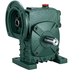
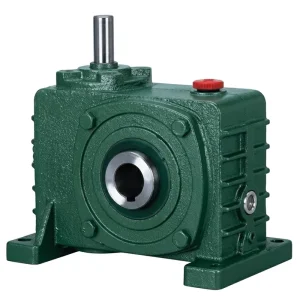

Capping Head Drive Requirements and Reducer Selection
Capping machines impose a distinct set of drive requirements that differ from filling pump drives. A screw capping head applies a defined torque to tighten a closure to a specified torque value — typically measured in Newton-metres and controlled by a torque-limiting clutch on the spindle. The enväxlad snäckreducerare driving the capping head must deliver sufficient output torque to spin the capping spindle at the target speed against the clutch disengagement torque, while maintaining that speed consistently across every bottle on the line.
In rotary capping machines common in beverage facilities across Australia, Canada, and Colombia, a central input shaft drives multiple capping heads arranged around a rotating carousel. The main drive reducer sets the carousel rotation rate, while individual heads may be driven by a secondary reducer geared to the carousel speed. In both arrangements, the snäckväxelreducerväxellåda provides the torque multiplication needed to achieve the capping head spindle torque without requiring an oversized motor — a useful characteristic given the space constraints of rotary machine carousels.
For press-on caps and crown seal applications, the drive requirement shifts from torque to precise vertical stroke rate. Here the reducer controls the cam-driven vertical motion of the capping head at a stroke rate synchronised to the container indexing speed. Any speed variation between the indexer drive and the capping drive causes misalignment between the container and the descending cap head — resulting in either a skewed closure or a missed container entirely. The fixed ratio of the enstegs hastighetsreducerare eliminates this variation at the drive level when both drives are correctly specified.
Filling Machine Drive Applications Across Global Packaging Markets
Filling and capping equipment requirements vary by region according to product type, regulatory framework, and electrical infrastructure. The table below summarises how these regional factors influence enväxlad reducerväxel specification for filling machine drives.
| Område | Dominant Filling Application | Motor Standard | Reducer Specification Note |
|---|---|---|---|
| Australien | Beverage, dairy, and food packaging | 415 V, 50 Hz | Seal integrity important in beverage washdown environments; IP54 housing protection preferred |
| Storbritannien | Pharmaceuticals, health & beauty, FMCG liquids | 400 V, 50 Hz | CE compliance required; oil containment and hygiene critical in pharmaceutical filling environments |
| Netherlands | Chemicals, food condiments, export packaging | 400 V, 50 Hz | Long maintenance intervals required for multi-shift port logistics packaging lines; larger oil capacity models preferred |
| South Korea | Cosmetics, electronics cleaning fluids, food sauces | 380 V, 60 Hz | 60 Hz input increases output speed by 20% versus 50 Hz — verify output rpm against fill rate requirements and adjust ratio if needed |
| Kanada | Dairy, nutraceuticals, cold-room pharmaceutical | 600 V / 480 V, 60 Hz | Cold-start oil viscosity must remain pumpable at minimum facility temperature; synthetic gear oil recommended for cold-room installations |
| Brazil / Colombia | Beverages, cleaning products, edible oils | 380–440 V, 60 Hz | Elevated ambient temperatures in some production areas; confirm rated ambient range and consider ventilation around reducer housing |
Complementary Products for Filling Line Drive Systems
A filling and capping machine drive system requires more than the reducer alone. Matched motor and gearbox pairings from a common supply source reduce engineering uncertainty and simplify after-sales support across globally distributed packaging facilities.


Vanliga frågor
Redaktör: PXY