
Packaging & Logistics · Automated Storage
A technical reference for warehouse automation engineers, systems integrators, and procurement teams in Germany, Japan, South Korea, the United States, and other markets deploying ASRS infrastructure in distribution and manufacturing facilities.
Why ASRS Drive Systems Depend on Precise Speed Reduction
Automated Storage and Retrieval Systems — ranging from unit-load stacker cranes serving high-bay warehouses to miniload systems handling totes and cartons, and from vertical lift modules to horizontal carousel storage units — all share a fundamental mechanical requirement: controlled, repeatable motion at low speed with high torque. The drive mechanisms that move storage/retrieval machines along rack aisles, raise and lower load-handling devices, extend extraction forks, and rotate carousel shelves cannot tolerate speed variation, positional drift, or transmission backlash beyond tightly defined limits.
A single speed reducer placed between the drive motor and the driven mechanism provides the speed reduction and torque multiplication needed to meet these requirements within a compact, standardized housing. The worm gear speed reducer’s right-angle output geometry, inherent self-locking at higher gear ratios, low noise level, and ability to accept direct motor mounting make it a practical fit for multiple drive points within a typical ASRS installation. Understanding the specific demands of each drive axis helps engineers match the correct model, ratio, and mounting configuration from the WP series single stage range.

Tillverkningsstruktur
The WP series single speed reducer is built on an integral cast-iron housing that is bored, faced, and finished in a single CNC setup. This single-setup machining approach ensures that the center distance between the worm shaft bore and the output wheel shaft bore is controlled to a dimensional tolerance that directly determines gear mesh quality — even tooth load distribution, consistent backlash, and smooth transfer of torque without the sudden micro-deflection events that cause positioning errors in ASRS shuttle and crane drives.
Both input and output shafts are supported by precision rolling element bearings located in machined bearing pockets at either end of the housing. For ASRS crane travel drives, where the output shaft typically connects via a chain or gear coupling to the travel wheel axle, the dual-bearing support manages the combined radial load from chain tension and the reaction moment from the drive wheel on a rail surface. For vertical lift drives, the axial load from counterweight system dynamics must also be handled — in these applications, the bearing arrangement inside the reducer must be confirmed against the axial load component before specifying a frame size.
Input shaft configurations cover the full range of ASRS motor mounting requirements. Direct flange-input models (WPKA, WPDKA) accept IEC-standard brake motors — the standard motor type on ASRS lifting drives where the integrated motor brake holds the load-handling device in position when the motor is de-energized. Foot-mounted variants (WPDS, WPKS) suit installations where the motor and reducer are mounted on a common structural sub-frame with a flexible coupling between them, a common arrangement in larger unit-load stacker crane travel drives where motor and reducer are both significant masses and vibration isolation between them is desirable.
Materialsystem
The housing material is gray cast iron across the standard WP series range. Gray iron’s inherent damping capacity — higher than that of steel or aluminum — attenuates the vibration generated by the drive motor and gear mesh before it transmits into the ASRS structural frame. In high-bay warehouses in Germany and Japan where rack-supported buildings rely on the rack structure itself as the building envelope, minimizing transmitted vibration from drive mechanisms to the rack columns is an engineering consideration that gray iron housing material addresses without requiring separate vibration isolation mounts.
The worm shaft is machined from case-hardened alloy steel and finish-ground on the tooth profile after heat treatment. Ground worm geometry produces consistent, predictable sliding contact with the bronze worm wheel — a requirement in ASRS drives where the reducer must produce the same output position for a given number of input revolutions throughout its service life. Profile variation between teeth, which occurs in non-ground worms, introduces cycle-to-cycle positional scatter that accumulates into retrieval address errors in automated systems relying on open-loop motion control.
Worm wheels are cast from phosphor bronze or tin bronze, alloys that exhibit controlled wear against the hardened steel worm. The controlled wear characteristic is important in ASRS applications because wear-induced changes in backlash must remain within the tolerance budget allocated by the controls engineer — typically a few tenths of a millimeter of output shaft angular play. Bronze wheel wear is predictable from operating hours and load level, which allows planned replacement intervals to be established during ASRS commissioning rather than reacting to unexpected positional drift in the field.
Recommended Model for ASRS Crane and Shuttle Drive Points
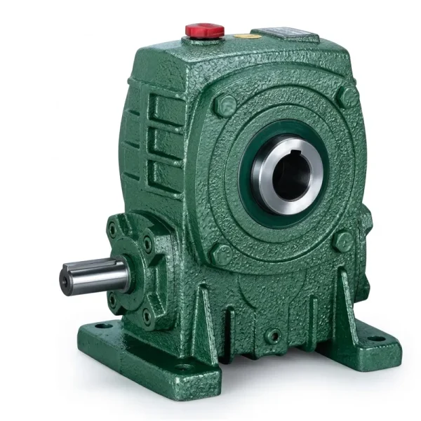
EP-WPKA — 5 to 260 kg Single Speed Reducer
The EP-WPKA is a flange-input single stage speed reducer with a solid output shaft, suited to ASRS travel and lift drives where a brake motor mounts directly on the reducer input face and the output shaft connects to the drive sprocket or pinion of the crane or shuttle travel mechanism. The flange input eliminates the need for a separate motor coupling, reducing the number of alignment-sensitive joints in the drive chain — an advantage in ASRS installations where the storage/retrieval machine travels continuously over a long aisle and periodic drive coupling inspection would require machine downtime. The unit weight range of 5 to 260 kg spans the full scale from miniload shuttle drives through heavy unit-load stacker crane travel units.
| Parameter | Värde |
|---|---|
| Unit Weight Range | 5–260 kg |
| Input Connection | IEC motor flange (direct mount) |
| Utgångskonfiguration | Solid shaft, single or double |
| Reduction Ratio (Single Stage) | 1:10 – 1:60 |
| Frame Sizes (center distance) | 40 – 250 mm |
| Ingångshastighet | ≤ 1500 rpm |
| Ambient Temp. Range | -40°C to +40°C |
Drive Axes in ASRS Machines and Their Reducer Requirements
A typical stacker crane ASRS installation has at least three mechanically distinct drive axes: the aisle travel drive that moves the entire machine along the ground-level rail, the mast lift drive that raises and lowers the load-handling device on the mast, and the extraction or fork drive that extends the load-handling device into or out of the storage location. Each axis operates at a different speed and torque point and may require a different reduction ratio, output shaft configuration, or mounting arrangement from the single speed reducer.
The aisle travel drive typically operates at moderate speed with continuous duty — the machine travels its full aisle length multiple times per shift. Travel speed for unit-load stacker cranes ranges from 60 to 180 m/min, which translates through the drive wheel diameter and gear reduction to an output shaft speed of 30–90 rpm for a typical drive arrangement. This falls within the coverage of a single stage worm reducer at ratios between 1:15 and 1:50 from a 4-pole motor, depending on the drive pinion or wheel diameter.
The mast lift drive presents different requirements: it must handle the combined weight of the load-handling device and the maximum rated load, and it operates in both lifting and lowering directions with a motor-brake holding the load during dwell at a storage address. A single speed worm reducer in the lift drive benefits from the self-locking tendency of worm gearing at higher ratios — at ratios above 1:30, the worm cannot be back-driven by the output load, providing an additional mechanical hold in the event of a motor brake malfunction. This is not a substitute for a properly rated motor brake per applicable safety standards, but it provides a secondary mechanical barrier that ASRS safety engineers value as part of a defense-in-depth approach.

Speed and Ratio Reference for ASRS Drive Points
The table maps the primary drive axes of common ASRS machine types to typical output shaft speed requirements and the corresponding single reduction ratio from a standard 4-pole motor at 1450 rpm. Final selection requires verification against the specific drive geometry, rated load, and cycle rate of the target installation.
| ASRS Machine / Drive Axis | Utgångshastighet (rpm) | Förhållandeintervall | Typical Input Power | Preferred Mounting |
|---|---|---|---|---|
| Unit-load stacker crane — travel | 30 – 90 | 1:15 – 1:50 | 3 – 15 kW | Flange / foot |
| Unit-load stacker crane — lift | 15 – 40 | 1:30 – 1:60 | 5.5 – 22 kW | Flange (brake motor) |
| Miniload system — shuttle travel | 50 – 120 | 1:10 – 1:25 | 0.37 – 2.2 kW | Flange or hollow shaft |
| Vertical lift module — carriage drive | 10 – 30 | 1:40 – 1:60 | 1.5 – 7.5 kW | Flange (brake motor) |
| Horizontal carousel — rotation drive | 2 – 8 | 1:60 (double stage for lower) | 0.75 – 3 kW | Foot |
| Fork extraction / extend drive | 20–50 | 1:25 – 1:50 | 0.12 – 1.1 kW | Flange or hollow shaft |
Hollow Output Shaft Configuration for Compact Shuttle and Fork Drives
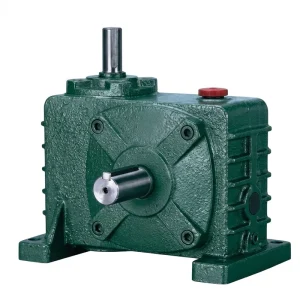
EP-WPZ — 0.4 to 5.2 L Oil Capacity Single Speed Reducer
The EP-WPZ features a hollow output shaft that allows it to mount directly onto the driven shaft of an ASRS shuttle travel wheel, fork drive roller, or extraction belt pulley without requiring an external coupling or shaft extension. This is a significant spatial advantage in miniload shuttles and vertical lift module carriages, where the available space for the drive package is strictly defined by the machine structural envelope. The oil capacity range of 0.4 L to 5.2 L corresponds to the range of frame sizes from the smallest single speed gear reducer units through the largest WPZ configuration, giving engineers the flexibility to specify the minimum frame size that meets the torque and thermal requirements of the application.
| Parameter | Värde |
|---|---|
| Oljekapacitetsområde | 0,4–5,2 liter |
| Utgångskonfiguration | Hollow bore, keyed or shrink disc |
| Input Connection | Solid shaft or motor flange |
| Reduktionsförhållande | 1:10 – 1:60 |
| Frame Sizes | 40 – 250 mm center distance |

Operational Considerations in ASRS Environments
ASRS installations in pharmaceutical distribution centers across Switzerland and the Netherlands, automotive parts warehouses in South Korea and Germany, and consumer goods fulfillment facilities across North America typically operate in temperature-controlled environments that sit within the standard ambient temperature rating of the WP series (-40°C to +40°C). However, cold-storage ASRS — serving frozen food warehouses operating at -25°C — requires specific attention to lubricant viscosity at startup. At these temperatures, standard mineral VG 220 gear oil becomes too viscous for reliable bearing rotation, and a synthetic PAO-base oil with a pour point below -40°C is the appropriate specification.
In high-cycle ASRS operations — some miniload systems in Japan and South Korea perform over 200 dual cycles per hour — the single speed reducer’s duty cycle loading is effectively continuous rather than intermittent. At this utilization level, the thermal rating of the selected frame size must be verified against the actual input power, reduction ratio, ambient temperature, and available airflow in the machine undercarriage. Units operating consistently near their thermal limit develop accelerated oil oxidation that shortens lubricant service intervals; in these applications, reducing the drain interval to 2,000 hours and using a synthetic lubricant are practical measures to maintain bearing and worm wheel condition across the extended operating life expected of ASRS installed in high-capital warehouse infrastructure.
Selection Criteria for ASRS Drive Engineers
Peak and Continuous Torque
Calculate both the peak torque at acceleration and the continuous running torque from the machine’s rated load, drive geometry, and acceleration profile. Apply a service factor appropriate for the ASRS duty cycle. ASRS lift drives with frequent start-stop require a higher service factor than steady travel drives.
Positioning Accuracy Budget
The gear backlash of the selected reducer contributes to the total positional error budget of the ASRS axis. Confirm that the backlash specification of the chosen frame size and ratio is within the budget allocated by the controls engineer, particularly for fork extraction drives where address accuracy determines whether the pallet or tote is correctly picked from its storage cell.
Brake Motor Compatibility
Lift and vertical drives on ASRS require brake motors to hold the load-handling device in position when stopped. Confirm that the motor flange standard of the selected reducer model (IEC B5 or B14) matches the brake motor’s flange configuration. Non-matching flanges require an adapter plate that adds axial length and a potential misalignment joint.
Lubrication in Cold Storage
ASRS installed in cold-chain facilities operating below 0°C require a lubricant with a pour point below the minimum expected ambient temperature. Specify a synthetic PAO or PAG gear oil rated for the operating temperature range and confirm compatibility with the reducer’s seal materials before filling, as cold-storage synthetic bases may require FKM seals rather than standard NBR.
Spare Parts Standardization
ASRS installations in large distribution centers in the United States and Australia may have dozens of drive points across multiple machine types. Standardizing on two or three WP series frame sizes across all drive axes reduces the spare parts inventory and simplifies technician training. A slightly oversized unit on lighter-duty axes is generally a better choice than specifying the minimum size for each individual drive.
Self-Locking as Secondary Hold
Worm reducers at ratios above 1:30 are inherently self-locking under static load. This characteristic provides a secondary mechanical barrier on lift drives in the event of a brake malfunction, but it should not replace a properly rated motor brake that meets the applicable machinery safety standard for the facility’s jurisdiction.
Kompatibla drivsystemkomponenter
ASRS drive systems require more than the reducer alone. The following products are manufactured to standards compatible with the WP series and are available for consolidated procurement:

Elmotorer
IEC-frame AC motors in B5 and B14 flange configurations are available to mount directly on the WPKA and WPDKA series input flanges. Brake motor variants — with an integral spring-applied, electrically released disc brake — are the standard configuration for ASRS lift and vertical drive axes. Motor frames cover the full power range of ASRS drive applications, from miniload shuttle drives below 0.5 kW through unit-load stacker crane travel drives up to 15 kW and beyond.

Snäckväxel
Horizontal carousel ASRS drives and slow-speed pallet shuttle systems requiring output speeds below those achievable from a 1:60 single stage ratio are served by the full worm gearbox series, which extends to universal and double-stage configurations. The shared casting geometry and seal standard between the single stage units and the multi-stage series means that spare parts kits — bearings, lip seals, oil fill plugs — remain consistent across both product families, reducing the variety of parts that ASRS maintenance teams must carry.
Om tillverkaren
The production facility carries ISO 9001:2015 certification and operates a vertically integrated manufacturing chain — from raw casting through precision CNC machining, gear grinding, heat treatment, assembly, and final load testing — entirely under one roof. The product range extends across worm gear reducers, planetary gear drives, agricultural gearboxes, power take-off shafts, hydraulic cylinders, sprockets, chains, gears, and motors, allowing ASRS OEMs and end-users to source multiple drivetrain components through a single qualified supplier with consistent dimensional and quality standards across product lines.
Casting materials span ductile iron, gray cast iron, cast steel, precision cast steel, and cast aluminum, with material selected to match the structural and weight requirements of each application. Standard and non-standard configurations are produced alongside each other: custom shaft lengths, special bore diameters, modified flanges, and non-catalogue ratios are available for ASRS builders who need a configuation outside the published range. All mating components — worm gears, sprockets, pulleys, and shafts — are produced in-house to tolerance standards that ensure first-fit installation without on-site modification.
Vanliga frågor
Redaktör: PXY