
LUBRICATION BEST PRACTICE GUIDE
A complete lubrication guide for round baler PTO shaft U-joint crosses, telescoping tube splines, and slip clutch components — covering grease specification, interval, quantity, and the field signs that tell you when the lubrication system has failed.
Greasing a round baler PTO shaft correctly is not complicated — but doing it incorrectly, or skipping it at the wrong moment in the operating cycle, is one of the most reliable ways to shorten a cross kit’s service life from two seasons to two months. The U-joint cross runs on needle rollers in precision-ground bearing cups; when the EP grease film between the needle rollers and the cup surface breaks down, the contact mode shifts from rolling to boundary lubrication within minutes and to dry metal-on-metal contact shortly after. At 1000 RPM, that transition from lubricated to dry running takes the cross from normal fatigue life to acute failure in a fraction of a single operating shift.
This guide covers every lubrication point on a round baler PTO shaft — the U-joint crosses, the telescoping tube spline profile, and where relevant the slip clutch bearing — along with the correct grease specification for each, the interval that matches the expected operating conditions, and the quantity indicators that confirm grease has reached the needle roller contact surfaces. The guidance applies to Series 4, 6, and 8 shafts across the main baler platforms used globally: John Deere, CASE IH, Krone, and New Holland round balers.
Why Lubrication Is the Primary Determinant of Cross Kit Service Life
Every U-joint cross in a round baler PTO shaft operates under a combination of torque load and angular deflection that places the needle rollers in the bearing cups under significant Hertzian contact stress. The grease film between the needle roller surface and the cup bore is the only element separating rolling contact from surface-to-surface metal contact. This film is typically between 0.5 and 2 micrometres thick — thinner than a human hair — and it depends entirely on fresh grease being pumped through the cross body channel to each cup at regular intervals. When the film breaks down, the needle rollers begin to pit and the cup bore surface begins to spall. Both processes are self-accelerating: damaged surfaces generate abrasive debris that reduces the contact area, raises the local stress, and accelerates further damage.
The critical point for a round baler PTO shaft operating at 1000 RPM is the sheer speed at which lubricant breakdown translates to component damage. At 1000 RPM the cross completes approximately 16 full bending cycles per second — and each revolution with a dry or degraded grease film deposits a small amount of wear debris in the cup. A cross that runs for two hours with a failed grease film in silage conditions — where water contamination is washing fresh grease away through the seals — can accumulate enough cup bore damage to require kit replacement before the end of the cutting shift. Greasing at the correct interval is not optional maintenance; it is the operational variable that most directly determines whether a cross kit lasts one season or four months.
Manufacturing Construction: Grease Paths Through the Cross Body
Understanding the physical path that grease takes from the nipple to the needle roller contact zone helps operators confirm that their greasing is actually reaching the right location — not just filling the cross body cavity without reaching the cups. In a standard agricultural series cross, the grease nipple is threaded into a port at the centre of the cross body — accessible on one face of the cross without removing the guard. When the grease gun is applied to this nipple, grease flows from the nipple bore into an internal channel that runs through the cross body to each of the four trunnion bases. From the trunnion base, grease enters the cup cavity through the clearance between the trunnion surface and the inner face of the cup, distributing along the needle roller length via the rolling action of the needles.
The seal at each cup end — a lip seal or triple-lip seal in quality kits — retains the grease in the cup cavity and excludes water and crop debris. The grease distribution path is correct when fresh grease appears at the outside lip of each seal face during greasing — this confirms that grease has reached the far end of each cup and that the path through the cross body is clear. If grease does not appear at one or more seal faces after a standard greasing cycle, that cup’s channel is blocked — typically by hardened old grease from a previous season’s accumulation inside the cross body bore — and the cross must be removed, cleaned, and re-greased or replaced. A blocked channel produces a dry cup even when the operator has applied grease through the nipple, which is why a cross that was greased on schedule can still fail if the internal path has silted up.
Grease Specification: What to Use at Each Lubrication Point
| Lubrication Point | Recommended Grease Type | NLGI Grade | Base Oil Viscosity | Anteckningar |
|---|---|---|---|---|
| U-joint cross and bearing cups | EP2 lithium complex | 2 | 200 cSt min at 40°C | Water-resistant; compatible with NBR seals |
| Telescoping tube splines | EP2 lithium complex | 2 | 200 cSt min at 40°C | Spread evenly on spline profile; not excess-filled |
| CV joint head (wide-angle) | EP2 lithium complex or OEM-specified CV grease | 2 | 150–220 cSt at 40°C | Check OEM spec — some CV heads require molybdenum-fortified grease |
| Lockback collar mechanism | Light machine oil or EP1 grease | 0–1 | Low viscosity | Thin film only; excess attracts crop debris |
| Guard bearing ring (where grease-able) | EP2 lithium complex or specified plastic-compatible grease | 2 | Standard agricultural | Some guard bearing rings are sealed and pre-filled for life |
The most critical specification at the U-joint cross is the grease’s compatibility with the seal material. Agricultural series cross seals are typically NBR (acrylonitrile-butadiene rubber). Calcium-soap greases — common in multipurpose farm greases — are not compatible with NBR seals and cause seal swelling that collapses the lip seal against the trunnion, restricting grease flow and eventually tearing the seal lip. Always confirm the grease base is lithium or lithium complex, not calcium, before applying to a round baler PTO shaft cross.
Greasing Intervals: Matching the Schedule to Field Conditions
The greasing interval for a round baler PTO shaft is not fixed — it scales with operating conditions rather than calendar time. The factors that accelerate grease degradation and seal wash-out are temperature, moisture, operating angle, and cycle frequency. A shaft running in dry hay conditions at 20°C with a stable 10° operating angle holds its grease charge substantially longer than the same shaft running in wet silage at higher ambient temperature with frequent headland turns that vary the operating angle through a wide range.
| Operating Condition | U-joint Cross Interval | Tube Spline Interval | Anteckningar |
|---|---|---|---|
| Dry hay, temperate climate | Every 8 hours | Every 20 hours | Standard manufacturer interval; suitable for UK dry seasons, Australian spring hay |
| Silage / high-moisture crop | Every 4–6 hours | Every 10–12 hours | Water ingress through seals accelerates grease wash-out; shorten interval accordingly |
| High-utilisation contractor operation | Every 6 hours minimum | Every 15 hours | Higher cycle count per hour means faster grease consumption; log all greasing events |
| High ambient temperature (above 35°C) | Every 6 hours | Every 15 hours | Heat reduces grease viscosity and oil separation rate; more frequent regreasing required |
| After any blockage event or pressure wash | Immediately | Immediately if wash-out suspected | Pressure washing and blockage heat both accelerate seal degradation; regrease before resuming |
Step-by-Step Greasing Procedure for a Round Baler PTO Shaft
The following procedure applies to a Series 6 round baler PTO shaft with a single central grease nipple on each cross — the most common configuration across John Deere, CASE IH, Krone, and New Holland round baler applications. Shafts with four individual nipples (one per cup) use the same procedure applied at each nipple rather than a single central nipple. Always grease with the shaft stationary and the tractor PTO disengaged.
Step 1 — Disengage the PTO and allow the shaft to stop completely. Greasing a rotating shaft is dangerous and ineffective; the centrifugal force disperses grease away from the needle roller contact zone. Confirm the shaft is stationary before approaching with the grease gun.
Step 2 — Clean the grease nipple on the first cross with a rag. Applying the grease gun to a nipple covered in soil, crop debris, or hardened old grease pushes contamination directly into the cross body bore and the needle roller cavity. A five-second wipe of the nipple face before connecting the gun prevents the most common route of abrasive contamination into the cross.
Step 3 — Attach the grease gun and pump slowly until fresh grease appears at all four seal faces. Pumping quickly generates excess pressure that ruptures the seals — particularly on worn or older seal kits — rather than distributing grease evenly through the cross. One slow stroke every two to three seconds is the appropriate rate. Stop pumping immediately when fresh grease is visible at all four seal lips; continuing to pump at that point has no additional benefit and forces grease behind the seal, washing out the old seal lip seal lubricant.
Step 4 — If grease does not appear at one or more seal faces after six to eight pump strokes, flag that cross for inspection. A cup that is not receiving grease through the cross body channel has a blocked internal bore. Continuing to pump adds pressure without distributing lubrication to the blocked cup. Remove the shaft for cross cleaning or replacement before the next operating shift.
Step 5 — Repeat for the second cross (at the implement end). Both crosses on the shaft are serviced at the same interval; skipping the implement-end cross because it is less accessible is a common error that produces asymmetric cross wear — with the implement-end cross failing first in nearly every case where this approach has been used.
Step 6 — Grease the telescoping tube splines. Retract the inner tube partially and apply a bead of EP2 grease to the visible spline profile along its full accessible length. Extend the shaft fully and compress it again to distribute the grease across the contact zone. This step is frequently omitted in field service because the guard makes the splines visually inaccessible; the guard must be slid back to access the spline end before greasing.
EP Round Baler PTO Shaft for Krone Round Balers — Triple-Lip Seal for Extended Grease Retention
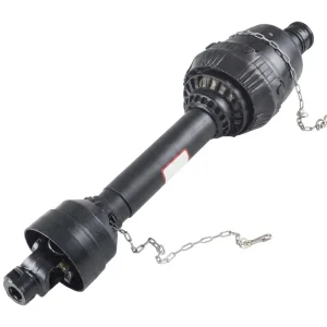
EP PTO Shaft for Krone Round Balers
A direct-fit round baler PTO shaft replacement for Krone round baler platforms including the KR and Comprima series. The cross kit uses triple-lip seals on all four cups — substantially extending the grease retention interval compared to dual-lip seals in wet silage conditions typical of northern Europe and New Zealand operations where Krone balers are widely used. The 20CrMnTi carburised crosses with precision-ground 52100 bearing cups provide consistent grease distribution across the full cross body bore. The central grease nipple is accessible through the guard assembly without removing the guard tube. Front yoke accommodates 1-3/8 in. × 21 spline 1000 RPM tractor outputs.
Recognising Lubrication Failure Before the Cross Fractures
Clicking at PTO Engagement
A metallic click during initial shaft rotation — typically in the first one or two revolutions after PTO engagement — indicates that needle roller play has developed in one or more bearing cups. This is the first audible sign of lubrication-induced wear; the cross still transmits torque but the cup bore has begun to enlarge. Immediate greasing and a cross play check are required before the next operating shift.
Heat at the Cross Body
A cross that is warm to the touch after stopping — noticeably warmer than the surrounding shaft tube — is generating heat through rolling friction above the normal level. This indicates an inadequate grease film on at least one set of needle rollers. The cross body temperature under correct lubrication runs close to ambient; elevated temperature means the lubrication film has thinned to the point where viscous friction is generating heat rather than forming a full film.
Vibration Under Load
Vibration felt through the tractor seat or heard as a cyclic noise during baling — not present when the baler is running empty — usually originates from a cross that has developed enough wear to produce a cyclic torque variation as the damaged cup section passes through the load-bearing zone. This stage is beyond early warning; the cross is close to fracture and must be replaced before the next operating period.
Reddish Debris Around Seals
Iron oxide (rust-coloured) debris accumulating at the seal face of one or more cups indicates fretting wear inside the cup bore — the needle rollers are micro-sliding against the bore surface under load rather than rolling cleanly. This is a sign of either inadequate lubrication or an oversized cup bore from previous wear. Inspect the cup bore condition and replace the cross kit immediately.
The Five Most Common Greasing Errors and Their Consequences
| Error | What Actually Happens | Result |
|---|---|---|
| Using calcium-soap multipurpose grease | Grease reacts with NBR seal material; seal swells and collapses against trunnion; grease path closes | Sealed cup runs dry despite nipple being charged; early cross failure |
| Not cleaning the nipple before greasing | Abrasive soil and crop residue pushed directly into the cross body bore by grease gun pressure | Abrasive contamination in needle roller contact zone; accelerated cup bore scoring |
| Pumping too fast and too much grease | Rapid grease pressure ruptures the thin lip seal; fresh grease blows past seal and out; seal loses its sealing function | Seal lip damage; reduced retention; shorter regreasing interval needed or early cross failure |
| Greasing only one cross (skipping the implement end) | Implement-end cross runs dry; wears faster than tractor-end cross; fails first | Asymmetric cross wear pattern; implement-end cross requires kit replacement more frequently |
| Not confirming grease appears at all four seal faces | One or more cups has a blocked internal channel; no grease reaches that cup despite nipple being charged | Dry cup fails within one to two operating shifts; operator believes they greased correctly |
Components That Benefit From Coordinated Lubrication Management
The lubrication programme for a round baler PTO shaft is most effective when the adjacent driveline components — particularly the baler input gearbox and any universal driveshaft in the fleet — are serviced on a coordinated schedule. Inspecting the gearbox input bearing for play and the universal shaft’s cross kit condition at the same greasing visit extends the value of the stop without adding significant time to the overall service event.
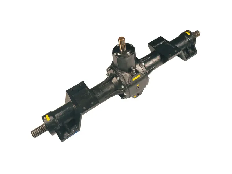
The baler input gearbox receives its lubrication from the internal oil bath rather than through a grease nipple, but the input shaft bearing — the connection point with the round baler PTO shaft’s implement-end cross — can show early wear that becomes visible as shaft runout or bearing noise during the same stop used for shaft greasing. A brief hand-check of the input stub for radial play during each 50-hour cross inspection adds no significant time and provides early warning of gearbox bearing wear before it becomes a gearbox repair.
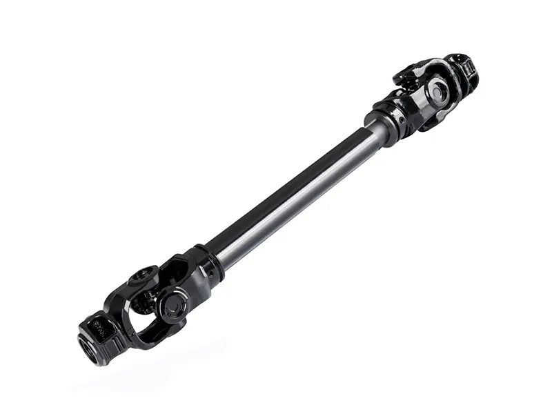
For operations that carry a universal PTO driveshaft as a spare, ensuring the spare shaft’s crosses are also maintained on a grease schedule — rather than stored dry — prevents the spare from arriving at the point of need with a cross kit already at the end of its service life. A spare shaft that is greased every 30 days during storage and checked for radial play before each season opens is as ready for immediate service as the shaft it is replacing.
Om tillverkaren
The product range covers agricultural gearboxes, worm gear reducers, planetary gear drives, power take-off shafts, hydraulic cylinders, gears, chains, and motors — manufactured under ISO 9001:2015 certification applied across all production stages from incoming material inspection through assembly and final load testing. Gearbox housings and structural components are produced in ductile iron, cast iron, cast steel, precision cast steel, and cast aluminium, with material grade selected by application. Custom and non-standard components — sprockets, worm gears, precision shafts, pulleys, and assemblies — are engineered and produced to customer drawings or application descriptions, with written quotation provided within 24 hours of a technical inquiry.
Verkstad




Vanliga frågor
Redaktör: PXY