
Automotive & Heavy Equipment — Application Focus
A technical guide for press line engineers covering single speed reducer selection, shock load management, and drive system architecture for coil feeders, transfer bars, and destacking equipment in high-tonnage automotive stamping operations.
Stamping Press Feeders and the Mechanical Demands They Place on Drive Components
High-tonnage automotive stamping press lines — producing body panels, structural brackets, door inners, and chassis components at facilities in Japan, Germany, the United States, Mexico, and South Korea — operate at stroke rates between 8 and 40 strokes per minute depending on the press type and part complexity. Each working stroke delivers an intense instantaneous force to the tooling, followed by a return stroke that allows the feeder to advance the coil strip or transfer the blank to the next station. The drives that move these feeder and transfer mechanisms must start and stop with precision at each stroke cycle, sustaining this cyclic loading pattern across multi-shift production weeks with minimal intervention.
The single speed reducer in a stamping press feeder or transfer mechanism serves a fundamentally different duty from a continuous-running conveyor or pump drive. Rather than delivering a constant output torque at steady state, the press feeder single speed gear reducer must absorb the inertial shock of direction reversal at the end of each feed stroke, tolerate the vibrational energy transmitted through the press foundation from the main slide impact, and maintain precise output shaft positioning accuracy that determines the feed length — and therefore the material utilisation and part dimensional consistency — of every part produced on the line.

Manufacturing Structure & Material System for Press Line Service
Housing Rigidity Under Shock Loading
Press line environments subject every mounted component to continuous percussive vibration from the main press slide impact — forces that can reach several times the static weight of the tooling in the first milliseconds after impact. The single speed reducer housing must maintain its dimensional stability under this background vibration without fatigue cracking at the bearing boss transitions or oil seal housing bores. HT250 grey cast iron is the standard material for press line single speed reducer housings; for the heaviest applications above 400-tonne press capacity, housings in SG (spheroidal graphite) ductile iron provide higher tensile strength and superior fatigue resistance under the cyclic shock loading profile of a high-stroke-rate press. All bearing seat bores are finish-machined in a single setup to eliminate alignment error that shock loading would otherwise amplify over time.
Worm Shaft: Hardened and Ground for Backlash Control
The feed length accuracy of a coil feeder or transfer bar depends directly on the backlash in the single speed reducer drive chain. In a worm gear reducer, backlash is primarily controlled by the worm shaft thread form accuracy and the worm wheel tooth conjugacy. For press line service, the worm shaft is manufactured from 20CrMnTi alloy steel, carburised, case-hardened to HRC 58–62, and finish-ground on a CNC worm grinding machine after hardening. The grinding pass produces a lead accuracy and thread form geometry that minimises the rotational dead zone during feed direction reversal — directly reducing the positional error at the feeder rolls or transfer finger that would otherwise accumulate into a dimensional defect in the stamped part.
Worm Wheel Bronze Specification for Cyclic Impact Duty
The worm wheel in a press feeder single speed reducer experiences a loading profile that differs significantly from steady-state process machinery: each feed stroke imposes a defined torque pulse, followed by a full stop and direction reversal. This cyclic impact loading fatigues the tooth root of the bronze worm wheel faster than steady-state loading at the same average torque level. ZCuSn10P1 tin-phosphor bronze provides the combination of high compressive strength, good fatigue resistance, and acceptable friction coefficient against the hardened worm shaft that makes it the standard specification. The bronze rim wall thickness is calculated to provide at least 2.5× the theoretical minimum for the rated torque — a safety margin that accommodates the dynamic amplification of feed stroke impact without progressive tooth root cracking.
Output Shaft Bearings Under Combined Loading
The output shaft of a press feeder single speed reducer carries radial loads from the feed roll or cam mechanism and axial thrust from the worm mesh reaction simultaneously. At high stroke rates, these loads vary at the same frequency as the press cycle — typically 10 to 30 Hz — creating a dynamic bearing loading condition that must be within the bearing’s dynamic load rating at the operating speed and duty cycle. Paired tapered roller bearings pre-set to a controlled axial preload are used on output shafts in the WPKS and WPDKA series — the configurations most commonly specified for stamping press feeder drives. The preload eliminates internal clearance that would otherwise allow shaft deflection under the cyclic radial load, preventing the orbital motion that accelerates roller fatigue in lightly loaded clearance-fit bearings operating under alternating load direction.
Service Factor Selection for Press Feeder and Transfer Drives
The service factor applied to a single stage speed reducer in a stamping press application is substantially higher than for a steady-state industrial drive. The reason is the dynamic amplification of torque at feed stroke reversal: when the feed rolls decelerate to zero and reverse at the end of each stroke, the kinetic energy of the moving feed mass is absorbed by the drive train components — including the single speed reducer output shaft coupling and the worm wheel tooth contacts. This energy creates a torque spike that can reach 2.5 to 4 times the steady-state running torque, depending on the strip mass, feed length, and press stroke rate.
Industry practice at German and Japanese press line OEMs specifies a service factor of 2.0 to 3.0 for cyclic feeder drives on mechanical eccentric presses, and 1.75 to 2.5 for servo-driven feeders where the acceleration and deceleration profile is actively controlled to reduce peak torque. The higher service factor for mechanical feeders reflects the unpredictable torque spike at stroke synchronisation — when the feeder index completes at the same moment the press slide begins its downstroke, the impact transmitted through the bolster into the feeder can briefly backdrive the feeder rolls, generating a torque reversal in the single speed reducer that exceeds the forward-direction peak. The worm gear reducer’s self-locking property at higher ratios provides a useful mechanical limit on this backdrive torque, which is one reason worm gear speed reducers are specified for press feeder applications rather than helical units that would transmit the full backdrive impulse back through the drive train.

Single Speed Reducer Selection Parameters by Press Feeder Type
Key specification parameters differ across the main feeder and transfer mechanism types found in automotive stamping lines. Use this table as a starting framework before confirming the final selection against the specific press line OEM’s drive train specification.
| Feeder / Transfer Type | Typical Output Speed (RPM) | Common Ratio | Servicefaktor | Self-Lock Required | Rekommenderad serie |
|---|---|---|---|---|---|
| Mechanical roll feeder | 15 – 40 | 1/30 – 1/60 | 2.5 – 3.0 | Yes | WPKS / WPDKA |
| Servo-driven roll feeder | 20 – 80 | 1/10 – 1/30 | 1,75 – 2,5 | Desirable | WPKA / WPKS |
| Transfer bar mechanism | 8 – 20 | 1/40 – 1/60 | 2.0 – 3.0 | Yes | WPDKA / WPKS |
| Destacking / blank conveyor | 20 – 60 | 1/15 – 1/25 | 1,5 – 2,0 | Not typical | WPDS / WPKA |
| Scrap chopper drive | 60 – 150 | 1/5 – 1/15 | 1,75 – 2,5 | Not required | WPDS / WPZ |
Recommended Models for High-Tonnage Press Line Applications
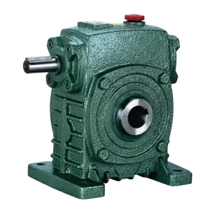
EP-WPKS Single Speed Reducer (4–365 kg)
The WPKS series addresses the combined output shaft loading that characterises transfer bar and heavy roll feeder drives — the output shaft must simultaneously carry the radial load from the cam or crank mechanism and the axial worm mesh reaction, both of which reverse direction at each press stroke cycle. Its paired tapered roller bearing output shaft arrangement maintains shaft centreline accuracy under these cyclic combined loads. The unit range from 4 to 365 kg covers single-station feeder drives through to multi-station transfer line main drives on 400-to-800-tonne tandem press lines in North American and European automotive body shops. Self-locking at ratios of 1/30 and above provides passive protection against backdrive during press impact.
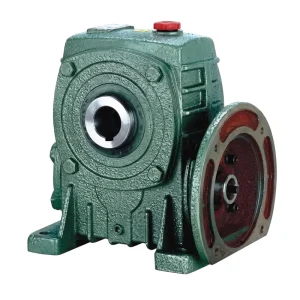
EP-WPDKA Single Speed Reducer (5–350 kg)
The WPDKA series is suited to the heaviest-duty transfer mechanism drives on tandem and progressive die press lines where multiple slide strokes per die set must be synchronised through a common drive shaft connected to individual single speed reducers at each station. Units from 5 to 350 kg cover the full range from light-duty part transfer slides through to the main transfer bar drives on 1,000-tonne-class large-panel presses. The dual output shaft option in the WPDKA allows a single drive unit to power both sides of a symmetrical transfer bar simultaneously, eliminating the cross-shaft timing errors that arise when two separate single speed reducers are driven from independent motors on opposite sides of a press bed.
Lubrication and Contamination Control in Press Shop Environments
The stamping press shop environment presents a specific contamination risk for single speed reducer lubricants that does not exist in most other industrial drive applications: metal stamping lubricant (drawing oil, press oil, or dry lubricant in more recent formulations) is applied to the strip or blank before each forming stroke, and the mist and splatter from this application reaches all surfaces within several metres of the press bed. If this stamping lubricant penetrates the worm gear reducer gearbox through a deteriorated shaft seal, it mixes with the gear oil and severely degrades the lubricant film load capacity — potentially within a single shift on a high-volume press.
Compatible Drive Components for Press Line Integration
Stamping press feeder drive systems require matched components across the complete drive train — from the servo or induction motor through the single speed reducer to the feed rolls or transfer mechanism. Sourcing these elements from a coordinated product range simplifies the procurement specification and provides a unified technical contact for drive train integration questions.
Elmotorer
IEC B3 and B5 frame motors in IE2 and IE3 efficiency classes, available in sizes matched to the input flange dimensions of the WPKS and WPDKA single speed reducer series. For servo-driven feeder applications, the motor specification must include the thermal class and rated S3 or S4 duty cycle appropriate for the press stroke rate and feed index profile.

Snäckväxelserie
The full snäckväxel product range provides complementary options for secondary drive positions on press lines — scrap conveyor drives, die change cart drives, and coil reel brake mechanisms — that share the press shop environment and maintenance schedule with the main feeder single speed reducer. Sourcing secondary gearboxes from the same product family simplifies lubricant rationalisation and spare parts management at large stamping facilities operating multiple press lines.

Tillverkningskapacitet
Our production covers worm gear reducers, industrial gearboxes, planetary drives, power take-off shafts, hydraulic cylinders, gears, chains, and motors — a range that supports complete drive package specification from a single facility. The production site operates under ISO 9001:2015 certification, with gear cutting, heat treatment, CNC tooth grinding, and assembly all conducted in-house under a documented quality management system that provides full traceability from raw material intake through finished unit despatch.
We design and produce standard and custom gearboxes and assemblies in ductile iron, grey cast iron, cast steel, precision investment cast steel, and cast aluminium. Our component catalogue includes gears, sprockets, worm gears, pulleys, worm shafts, and non-standard transmission parts made to buyer engineering drawings. For press line OEM and Tier 1 supplier procurement teams, documentation packages including ISO 9001 certificates, material test records, gear inspection reports, and factory run-test data are available on request.
Verkstad




Vanliga frågor
Q1. What service factor should I apply when selecting a single speed reducer for a mechanical roll feeder on a 500-tonne tandem press line in a Japanese automotive stamping plant?
For a mechanical roll feeder synchronised to a 500-tonne press at a stroke rate of 12 strokes per minute in a Japanese automotive body panel stamping facility, a service factor of 2.5 to 3.0 applied to the calculated steady-state drive torque is the appropriate starting point. The higher end of this range applies when the feeder synchronisation is driven directly from the press crankshaft through a cam and linkage mechanism with no electronic speed control, because mechanical synchronisation introduces the highest peak torque at the feeder reversal point. When the feeder incorporates an electronic cam profiling system that shapes the acceleration and deceleration ramp, the service factor can be reduced to 2.0 to 2.5. Multiply the service factor by the steady-state output torque required to move the strip weight plus the feed roll clamping preload, then verify this against the single speed reducer’s rated output torque for the selected housing size and ratio. Japanese press OEM specifications such as those from Aida, Komatsu Industrials, and Amino Industries typically state the feeder service factor requirement explicitly in the drive interface specification document.
How do I determine the correct worm gear reduction ratio for a transfer bar drive on a three-station progressive die press line in a North American automotive stamping facility?
The ratio selection for a transfer bar drive starts from the required transfer bar speed at the end of the advance stroke — typically expressed as a linear velocity in millimetres per second at the transfer fingers. Convert this linear velocity to rotational speed at the transfer drive shaft using the pitch circle radius of the crank or cam that drives the bar. Divide the motor’s rated speed (typically 1,450 RPM for a 50 Hz or 1,750 RPM for a 60 Hz four-pole motor) by this required shaft speed to obtain the reduction ratio. For North American 60 Hz installations on tandem press lines where the transfer bar advances at 150–300 mm/s with a 200 mm crank radius, the required output speed is typically 7–15 RPM, giving a ratio of approximately 1/120 to 1/117 — beyond the single-stage worm gear range of 1/60. In these cases, a two-stage arrangement (primary single speed reducer plus secondary chain or helical stage) is required, or the motor speed is reduced through a VFD to bring the ratio within the 1/60 single-stage range.
Q3. Which single speed worm gear reducer series provides the best self-locking protection against press impact backdrive for a coil feeder on a 300-tonne progressive die press in a German stamping operation?
For a coil feeder on a 300-tonne press at ratios of 1/30 and above, the WPKS series provides reliable self-locking under the impact backdrive conditions generated at the moment of slide contact. The self-locking condition in a worm gear reducer is achieved when the worm lead angle falls below the mesh friction angle — typically below approximately 7 degrees in a well-lubricated bronze-on-hardened-steel contact, corresponding to ratios of 1/20 to 1/25 and above depending on the specific worm geometry. At a 1/40 ratio, the WPKS operating at ambient German press shop temperatures with ISO VG 220 mineral worm gear oil provides a reliable self-lock under the typical backdrive torque magnitudes generated by 300-tonne press impact. Confirm the self-locking condition with the supplier at the specific ratio, oil temperature, and estimated backdrive torque magnitude — the self-lock is not guaranteed at all operating conditions and should be treated as a passive safety feature rather than a primary holding mechanism for personnel protection.
Q4. What type of shaft seal should I specify for a single speed gear reducer on a press feeder drive where sulphurised drawing oil is used at an automotive stamping facility in South Korea?
In a South Korean automotive stamping facility using sulphurised drawing oil on the strip or blank, the standard NBR lip seals fitted to most catalogue single speed reducer units will show accelerated degradation — sulphur compounds from the drawing oil attack the NBR polymer matrix, causing the seal lip to harden and crack within 3,000 to 6,000 operating hours. FKM (Viton) lip seals are the correct replacement specification in this environment; FKM is resistant to sulphurised oil compounds and maintains its sealing lip flexibility over extended service periods. For the output shaft closest to the die space — where oil mist concentration is highest — adding a labyrinth shield outside the primary FKM seal provides a first-stage mist barrier that can extend the primary seal life by 50–100% in heavy mist environments. Document the seal material specification in the gearbox installation record to ensure the correct replacement seal is used at future maintenance interventions.
Q5. Where can press line integrators in Mexico source a customised single speed reducer with dual output shafts for synchronising both sides of a transfer bar on a 600-tonne tandem press line?
The WPDKA series single speed reducer is available in a dual output shaft configuration that synchronises both sides of a transfer bar from a single motor-gearbox drive unit. Press line integrators in Mexico sourcing for a 600-tonne tandem press installation should specify the required output torque per shaft, the output shaft diameter and keyway dimensions to match the transfer bar coupling flanges, and the physical envelope constraints imposed by the press bed structure between the two output shaft connections. Standard lead time for the dual-output WPDKA configuration is 4 to 6 weeks from drawing approval. For tandem press line projects under OEM tooling approval — where dimensional and performance documentation is required for Tier 1 supplier qualification — a full documentation package including ISO 9001 certificate, material test records, and factory run-test data should be requested at the quotation stage and confirmed as part of the purchase order terms.
Redaktör: PXY