
A technical review of worm gear reducer selection, material requirements, and drive architecture for seawater reverse osmosis and multi-stage flash desalination facilities worldwide.
Desalination plants convert seawater or brackish water into potable water through processes that demand precise, continuous, and mechanically reliable pump drives. Feed pumps move raw seawater at moderate pressures through pre-treatment stages, while high-pressure pumps force water across reverse osmosis membranes at pressures typically between 55 and 82 bar. Both pump types place specific demands on their drive systems: sustained torque, minimal vibration transmitted to piping, and absolute resistance to the corrosive atmospheric conditions found at coastal installations in Saudi Arabia, Australia, Israel, the UAE, Spain, and Chile.
UN réducteur à vitesse unique built around the worm gear principle addresses several of these demands simultaneously. Its compact right-angle geometry fits naturally into constrained pump room layouts on modular desalination skids. The sealed cast-iron housing resists salt-laden air that degrades belt-drive and chain-drive alternatives within months of coastal installation. This article examines how the réducteur à vitesse unique integrates into desalination pump drive systems, covering mechanical structure, material selection, lubrication strategy, and installation practice.
Why Desalination Pump Drives Require Careful Reducer Selection
Seawater reverse osmosis systems operate continuously, often 24 hours a day with planned shutdowns measured in days per year. This duty profile means any mechanical component in the drive train must sustain rated torque and speed indefinitely without degradation. Feed pumps handling raw seawater typically operate between 200 and 600 rpm at the impeller shaft, while booster and high-pressure pump drives may demand output speeds as low as 150 rpm with output torques that would stall a direct-coupled motor at synchronous speed.
The worm speed reducer converts motor speed to the required pump shaft speed through a single mesh stage, eliminating intermediate shaft couplings and the alignment tolerances those couplings require. In a saltwater environment where humidity is persistently high and airborne chloride concentrations are elevated, reducing the total number of rotating joints and sealing faces directly reduces the number of corrosion entry points into the drive assembly.

Manufacturing Structure of WP-Series Single Speed Reducers
The structural core of the WP-series réducteur à vitesse unique is an integral one-piece housing bored and machined on a single setup. This ensures the center distance between the worm shaft and worm wheel shaft — the dimension governing tooth backlash and contact ratio — is held to design tolerance regardless of production volume. Housing rigidity matters in pump drive applications because pressure-induced deflection of the pump casing can apply bending moments at the coupling face that transmit into the gearbox housing; a rigid integral casting resists these external loads without distorting the gear mesh geometry.
The worm shaft is hobbed and ground from alloy steel bar, then case-hardened to 58–62 HRC at the threaded working surface. Grinding after heat treatment restores the involute profile to a tolerance that direct-hobbed unhardened worms cannot achieve. This surface accuracy determines the uniformity of the lubricant film across the contact zone — film uniformity is what separates a quiet, long-lived worm from one that generates elevated noise and localized wear. The worm wheel is cast in phosphor bronze and machined to mate with the worm profile, with the tooth form hobbed to match the worm lead and pressure angle precisely.
Input and output shaft assemblies are supported by rolling element bearings sized for both radial loads from transmitted torque and the axial thrust loads inherent to worm mesh geometry. Tapered roller bearings at the worm shaft ends manage combined loading efficiently and allow preload adjustment during assembly — a process step that sets operating clearance and determines how the unit responds to thermal growth during the first hours of operation.
Material System for Coastal and High-Humidity Environments
Housing Castings
HT200 grey cast iron for standard duty; QT450 ductile iron where higher impact resistance is required. Both grades accept epoxy primer and chemical-resistant topcoat — the finish system recommended for units installed within 500 m of the ocean shoreline.
Worm Shaft Steel
20CrMnTi or 40Cr chromium-alloy steel, carburized to case depth 0.8–1.2 mm or induction hardened selectively at the thread zone. The tough core resists shock loading from pump cavitation events; the case resists Hertzian contact pressures at the mesh.
Worm Wheel Bronze
ZCuSn10Pb1 phosphor bronze, centrifugally cast onto the wheel rim for a dense grain structure. Bronze tolerates momentary overload by yielding slightly without fracturing — a property that matters when feed pump impellers encounter debris or when high-pressure pump discharge valves open under full differential pressure.
Seals and Bearings
Double-lip NBR oil seals at both shaft exits; PTFE-lipped seals available for elevated-temperature variants. SKF or equivalent bearings on input and output shafts. All seals and bearings are replaceable in the field without specialized tooling.
Reducer Type Comparison for Desalination Pump Drive Service
| Selection Criterion | Single Stage Worm Reducer | Helical-Bevel Reducer | Belt / Chain Drive |
|---|---|---|---|
| Right-angle output | Native geometry | Bevel stage required | Not applicable |
| Coastal corrosion resistance | Sealed cast-iron housing | Sealed housing | Exposed elements deteriorate |
| Self-locking on shutdown | Yes — high-ratio units | Non | Non |
| Vibration to pump casing | Low — sliding mesh contact | Moderate tooth-frequency excitation | Variable with belt tension |
| Reduction ratio (single stage) | 10:1 – 60:1 | 3:1 – 20:1 typical | 2:1 – 6:1 practical |
| Lubrication system | Splash — no pump, no filter | Splash or forced-lube | Dry or periodic greasing |
| intervalle de maintenance | Oil change only | Oil change + gear inspection | Belt/chain replacement cycle |
Featured Specification: EP-WPDS Single Speed Reducer
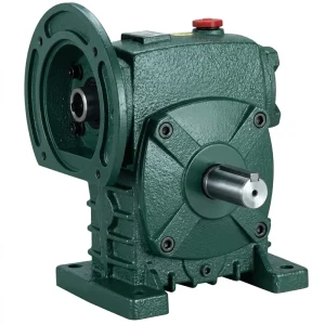
Le Réducteur monovitesse EP-WPDS is a flange-input, solid-output worm gear drive designed for direct motor coupling without an adapter plate. The WPDS configuration routes the input at right angles to the output shaft, making it a natural fit for inline pump configurations where the motor must sit perpendicular to the pump shaft. With an input power range of 0.12 to 15 kW, this model covers the auxiliary and pre-treatment feed pump segment — chemical dosing booster sets, pre-filtration feed lines, and permeate transfer pumps — where compact geometry and reliable low-speed torque delivery are the primary design criteria. The flange-face input accepts standard IEC motor feet directly, shortening installation time on skid-built units.
| Paramètre | Spécification |
|---|---|
| Plage de puissance d'entrée | 0,12 – 15 kW |
| Input Configuration | Flange-mounted (WPDS type) |
| Options de réduction du taux | 10 / 15 / 20 / 25 / 30 / 40 / 50 / 60 |
| Max Input Speed | 1500 r/min |
| Matériau du boîtier | Cast iron, foot and flange mount |
| Arbre de sortie | Solid, single or double |
Feed Pump Drives Versus High-Pressure Pump Drives: Different Torque Profiles
Feed pumps in seawater reverse osmosis plants move large volumes of water at moderate pressures — typically 3 to 6 bar — through screens, media filters, and cartridge filters before the high-pressure stage. Their impeller speeds range from 400 to 1200 rpm, and the role of the réducteur à vitesse unique is to match motor speed to the pump design point cleanly while the motor runs in its high-efficiency band at full synchronous speed. A réducteur à vitesse unique with a fixed ratio delivers this step-down without electronic control layers, reducing the number of failure modes in a continuously operated system.
High-pressure pump drives operate under entirely different mechanical conditions. The pump shaft sustains full differential pressure across the RO membrane stack — up to 82 bar in seawater service — and the radial loading on the shaft is substantial. Frame selection for high-pressure duty therefore requires a larger output bearing span than the power rating alone would suggest, and the reducer’s output shaft must handle cantilever loads without deflecting in a way that misaligns mechanical seal faces at the pump.
The worm gear reducer handles shock loads from valve events — fast-acting non-return valves and system startup transients — more gracefully than spur gear drives because the bronze wheel tooth deforms slightly and recovers, absorbing the impulse. This characteristic also explains why réducteurs de vitesse à vis sans fin outlast spur gear sets in pump service when cavitation events occur periodically at feed pump inlets.

Lubrication Strategy for Continuous-Duty Desalination Service
Worm gear reducers used as pump drives run at lower output speeds than most industrial applications, which means the oil splash pattern must carry lubricant to the upper worm thread even when the sump is at its minimum level. Housing designs in the WP series incorporate oil-guiding ribs cast into the interior walls that redirect splash toward the upper mesh zone, maintaining film continuity across the operating speed range. ISO VG 220 synthetic polyalphaolefin is the preferred lubricant for continuous-duty pump drives in high-ambient environments — its viscosity index above 150 maintains adequate film thickness at a 45°C sump temperature while starting cleanly at sub-zero winter temperatures common in Spanish or South African coastal sites.
A first oil change at 200–300 operating hours removes metallic particles generated during the worm-bronze break-in contact. Subsequent intervals of 4,000–6,000 hours are achievable with synthetic oil in a fully sealed housing. Seawater ingress into the oil is the dominant failure mode at coastal desalination sites; double-lip output shaft seals with a grease-filled cavity between the two lips provide a reliable second barrier in spray-zone installations found at tank-top pump rooms in Australian and Middle Eastern plants.
Mounting Configurations Suited to Pump Room Layouts
Foot Mount — WPA / WPDA
Flat base mounting on a steel frame or concrete pad. Used for larger feed pump sets where the gearbox sits adjacent to the pump on a common baseplate, with alignment achieved by shimming the motor and gearbox feet independently.
Flange Input — WPDS / WPKS
Motor bolts directly to the input face of the gearbox, eliminating the motor coupling. Preferred for factory-aligned skid-mounted pump sets shipped as complete units to site in Saudi Arabia, the UAE, or Chile.
Hollow Shaft — WPKA / WPKZ
The output bore slides onto the pump input shaft, secured by a key and end retainer. Removes the need for a separate shaft coupling and effective for retrofit drives where the existing pump shaft is intact and correctly sized.
Vertical Output — WPDKA
Output shaft directed downward or upward as required by pump orientation. The EP-WPDKA covers loads from 5 to 350 kg, making it the choice for vertical turbine pump configurations used at coastal water intake structures in Australia and the Middle East.

Efficiency and Application Boundaries
Single-stage worm reducers at 30:1 ratio typically deliver 70–80% mechanical efficiency, whereas a helical-bevel unit at the same ratio might reach 92–96%. For high-pressure pumps transferring several hundred kilowatts, this difference should be evaluated carefully against the cost and operational simplicity advantages of the worm drive. In auxiliary feed pump applications below 15 kW, the absolute power loss difference is small in monetary terms and is frequently outweighed by longer maintenance intervals, inherent self-locking behavior on shutdown, and greater corrosion resistance in the coastal environment.
Le réducteur à vitesse unique in worm configuration therefore finds its strongest value proposition in the sub-15 kW segment of the desalination drive market — pre-treatment pumps, chemical dosing pumps, permeate pumps, and brine dilution pump sets — where compact geometry, sealed splash lubrication, and robust coastal-grade housing construction address the actual site constraints more effectively than higher-efficiency but more complex alternatives. For high-pressure pump drives above 37 kW in continuous service, a helical-bevel unit with equivalent corrosion treatment may offer a better lifecycle energy cost and warrants a side-by-side engineering comparison before selection is finalized.
Composants compatibles du système d'entraînement
A well-matched drive system begins with mechanical compatibility across all components. Pairing the gearbox with a motor and worm gearbox from the same design family eliminates field adaptation work and simplifies spare-parts procurement for remote plant locations in Oman, Morocco, or the Atacama region of Chile.


À propos du fabricant
The manufacturing range extends across agricultural gearboxes, worm gear reducers, planetary gear drives, power take-off shafts, hydraulic cylinders, gears, chains, and motors. The production facility operates under ISO 9001:2015 quality certification, with documented inspection covering raw material receipt, in-process machining, heat treatment verification, and final load testing before shipment.
In-house capability includes precision casting in ductile iron, grey cast iron, cast steel, precision cast steel, and cast aluminum; gear hobbing and grinding; induction and carburizing heat treatment; and assembly with functional leak and load testing. Both catalog-standard and fully customized mechanical assemblies are produced from the same tooling infrastructure, supporting OEM procurement programs and aftermarket replacement across more than 60 countries.
Atelier




Foire aux questions
Éditeur : PXY