
Renewable Energy & Utilities · Solar PV Maintenance Automation · Worm Gear Reducer Drive Technology
Soiling loss is one of the most persistent efficiency penalties in utility-scale solar PV generation. Dust, pollen, and bird deposits reduce panel output by 1–7% per month in high-irradiance desert and semi-arid environments, with figures reaching 25–35% in sites adjacent to agricultural land or construction activity. Automated cleaning robots address this without water consumption or manual labor, traversing panel rows on drive mechanisms that must position brushes precisely, apply consistent contact pressure, and run reliably across years of daily cycles in environments that reach 50°C surface temperatures and sustained UV exposure. The réducteur à vitesse unique — particularly the compact worm gear configuration — is the drive component in these robots that converts motor output into the low-speed, torque-stable wheel or brush rotation that controlled panel traversal demands.
Why Solar Cleaning Robot Drive Mechanisms Are More Demanding Than They Appear
A solar panel cleaning robot operates on a tilted surface — panel arrays are typically inclined at 10–35° to maximize irradiance capture — which means the traversal drive must provide both forward motion and a braking force that prevents the robot from accelerating downslope under gravity when drive power is reduced or removed. On a 1,000 mm wide robot traversing at 0.1–0.3 m/s, the motor and drive train must handle not only the rolling resistance of the drive wheels against glass-surfaced panels but also the gravitational component of the robot’s mass resolved along the panel slope. A drive system that cannot hold position when unpowered creates a safety hazard — the robot can drift into end-stop structures or panel frame edges at low but damaging impact velocity.
The worm gear single speed reducer solves both requirements in a single unit. The fixed reduction ratio — typically 1:20 to 1:60 depending on wheel diameter and target traversal speed — converts a compact brushless DC or single-phase AC motor output into the low-speed, high-torque rotation the drive wheels need for controlled motion. At ratios above approximately 1:30, the self-locking property of the worm mesh prevents back-driving: when motor current is removed, the worm wheel cannot rotate the worm in reverse under the gravitational load component. This replaces what would otherwise be a separate electromagnetic brake or mechanical backstop, reducing component count in a robot that must be as compact and lightweight as possible to avoid panel load limits.

Structure de fabrication
The structural architecture of a compact WP-series single speed reducer centers on an integrally cast housing that positions the worm shaft and output shaft at 90° to each other with fixed bearing bore geometry. In a cleaning robot application, this right-angle arrangement is practically useful: the drive motor can be oriented along the robot frame’s longitudinal axis while the drive wheel shaft runs transversely, keeping the mechanical package within the width envelope of the robot body. The integral housing — produced as a single casting rather than assembled from bolted sections — maintains the bearing seat relationship that determines gear mesh backlash and tooth contact pattern throughout the service life of the unit.
For solar robot applications, the compact WPZ and WPKZ variants deserve attention. The Z-suffix WP models are characterized by their oil capacity range of 0.4–5.2 litres, covering the smaller frame sizes that suit the weight constraints of panel-mounted cleaning equipment. The WPKZ configuration adds a vertical motor-input flange to the compact oil-capacity frame, enabling direct coupling to small-frame brushless DC motors without an adapter plate. The housing’s flat external surfaces on the base and side faces allow direct bolting to extruded aluminum robot frames without a custom adapter bracket, which matters in robot structures where every additional machined part adds weight, cost, and a potential fatigue point under vibration from drive wheel impacts at panel frame joints.
Système de matériaux
Material selection for a worm gear speed reducer operating in solar field environments must account for factors that differ substantially from standard industrial drive applications. The housing exterior is exposed to sustained UV, wide diurnal temperature swings — 15°C night minimum to 50°C or above on daytime surface temperatures in Middle Eastern, Indian, or Southwest US desert installations — and periodic abrasive dust exposure. Grey cast iron (HT200) provides adequate mechanical strength for the compact frame sizes used in cleaning robots and its thermal mass helps buffer rapid temperature changes that would otherwise stress the gear oil film. For the smallest frame variants, cast aluminum housing is an option that reduces robot-mounted weight significantly, though its lower thermal conductivity requires attention to oil change intervals in high-ambient environments.
The internal wear pair follows the same material logic as standard WP-series industrial drives: the worm is alloy steel (20CrMnTi or 40Cr) case-hardened to 56–62 HRC and ground to precise tooth form, while the worm wheel is phosphor bronze (ZCuSn10Pb1). Bronze’s capacity to embed fine abrasive particles that enter the housing through imperfect seals — a realistic scenario in dusty solar field environments — rather than transferring those particles to score the hardened worm flank is particularly valuable in this application. In a cleaning robot that runs daily cycles in desert conditions, the gear oil is exposed to thermal cycling that accelerates oxidation; synthetic lubricants with higher oxidation stability are recommended over mineral grades for installations in high-ambient environments such as those in the Atacama, Rajasthan, or Sahara solar belt regions.
Speed and Traversal Control Requirements for Panel Cleaning Robots
Panel cleaning robots operate at traversal speeds calibrated to match the cleaning mechanism’s effective contact time with the panel surface. At speeds too high, the rotating brush or wiper blade does not dwell long enough to dislodge compacted dust; at speeds too low, the robot takes an impractically long time to complete a full row, reducing the number of rows cleaned per shift. Most utility-scale cleaning robots target traversal speeds of 0.1–0.4 m/s — roughly 6–24 m/min — across panel rows of 30–60 m in length.
For a robot with 100 mm diameter rubber drive wheels at 0.2 m/s target speed, the required wheel shaft speed is approximately 0.2 ÷ (π × 0.1) = 0.64 rev/s = 38 rpm. Running a compact brushless DC motor at 1,500–3,000 rpm through a single stage speed reducer at 1:40–1:60 delivers output in the 25–75 rpm range, neatly covering the traversal speed band. The torque requirement is modest for horizontal or low-tilt applications — robot masses are typically 15–40 kg — but increases significantly on high-tilt rows where the drive must overcome the gravitational downslope component and maintain consistent contact pressure across the full traverse. A worm gear speed reducer naturally provides higher torque at a given frame size than equivalent spur gear units of the same ratio, which keeps the drive package compact even when tilt-induced torque demand increases.
Recommended Model: EP-WPKZ for Compact Solar Robot Drive Duty
For solar panel cleaning robots and other precision traversal mechanisms that require a compact, flange-input worm reducer with a defined oil capacity, the EP-WPKZ (0.4–5.2 L Oil Capacity Single Speed Reducer) is a practical selection. The WPKZ designation combines the vertical-flange motor input of the KZ configuration with the compact oil-capacity frame range, covering the smaller center-distance models suited to lightweight robot drive train installations. The defined 0.4–5.2 L oil capacity range across frame sizes gives design engineers a precise oil volume to reference when specifying the lubrication top-up cycle in remote solar field maintenance schedules.
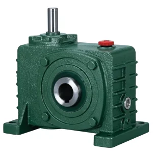
- Oil capacity: 0.4 L to 5.2 L across available frame sizes
- Reduction ratio: 1:10 to 1:60 (single stage)
- Vertical flange motor input for direct DC motor coupling
- Compact frame suits weight-limited panel-mounted robots
- Oil-bath lubrication; cast iron or aluminum housing variants
- Operating temperature: −40°C to +40°C ambient

Environmental Resistance in Desert and High-Irradiance Solar Field Conditions
The environmental stresses at large utility solar installations in the Middle East, North Africa, India, the American Southwest, Chile, and Australia are considerably more severe than those at typical industrial drive installations. Ambient air temperatures above 45°C, sustained UV irradiance on all exposed surfaces, and particulate loading from desert wind are the primary environmental factors that affect drive component life. The seal system on the single stage speed reducer is the first line of defense against all three: UV-stable lip seal elastomers maintain their flexibility and sealing contact pressure across the diurnal temperature swing rather than hardening and losing lip conformity as a standard rubber compound would over two to three years of outdoor exposure.
Ingress protection at the housing joints is a secondary consideration. WP-series integral cast housings have no parting-line gaskets along the primary load paths; the main leak points are the shaft seals and the breather plug, both of which can be addressed with higher-grade seal elastomers and a desiccant breather substituted for the standard open vent in high-dust environments. For installations in blowing-sand conditions in the Rajasthan solar belt or the Saudi Arabian Empty Quarter, specifying an IP55-or-higher motor rating paired with a sealed reducer with desiccant breather provides a combination that realistically reaches 5–8 year service intervals between planned overhauls — a maintenance cycle that aligns with the typical O&M contract structures at utility solar farms in those regions.
Integrating the Reducer into Brush Drive and Wheel Drive Subsystems
A solar panel cleaning robot typically carries two distinct drive subsystems: the traversal drive that moves the robot along the panel row, and the brush or wiper drive that spins the cleaning element at a speed calibrated to the panel surface material and the deposit type being removed. Both subsystems can employ a single speed worm gear reducer, though the torque and speed requirements differ. The traversal drive requires moderate torque at 20–80 rpm output; the brush drive may require higher speed — 200–600 rpm — with lower torque, in which case a smaller WP frame at a lower reduction ratio (1:10–1:15) provides the appropriate output.
Robot designers using a single speed reducer in both positions benefit from the commonality of mounting interface and lubrication type across the WP series. A single gear oil stock in the field maintenance kit covers both units; a single seal part number covers both shaft sizes if the frame dimensions are matched during design. For the drive wheel shaft, a hollow-bore output variant eliminates the coupling spider and shaft clamp that a solid output shaft requires, reducing part count and the periodic inspection that coupling element wear demands. In the robot structures used for tracker-mounted bifacial panel systems — increasingly common in utility-scale installations across Spain, Japan, and California — the reducer must also tolerate the gentle vibration generated by the tracker actuator and wind-induced panel resonance; the integral housing and oil-bath lubrication inherently damp this vibration without additional mounting isolation.

Maintenance Planning for Drive Reducers at Remote Solar Installations
Utility solar farms — whether in the Atacama Desert, the Thar Desert, or the Mojave — are typically located far from service centers, with O&M teams visiting the site on scheduled cycles rather than responding to individual equipment alerts. The maintenance strategy for any robot drive component must therefore prioritize long intervals, easily executed checks, and oil specifications that remain within viscosity limits across the full seasonal temperature range without requiring between-visit adjustments.
For a WP-series single speed reducer driving a cleaning robot in a high-ambient solar installation, synthetic ISO VG 220 gear oil provides the most practical lubricant: it maintains adequate film thickness at 50°C oil temperature while remaining pumpable at the near-zero morning temperatures that occur at high-altitude desert sites. The oil change interval with synthetic lubricant is typically 3,000–4,000 hours — approximately 18–24 months of daily-cycle robot operation — which aligns with the annual or bi-annual O&M visits that utility solar farm contracts provide. Seal inspection, breather check, and housing coating touch-up are the only additional items during those visits. This maintenance schedule is not dramatically different from what the same reducer would require in a standard factory installation, which is the baseline expectation for a correctly specified worm gear speed reducer in solar field duty.
Compatible Drive Components for Solar Robot Systems
A complete cleaning robot drive system needs components that are mechanically and electrically matched from motor through to drive wheel shaft. Two product families integrate directly with the WP-series reducers and are available from the same supply source.


À propos de nous
The product range covers agricultural gearboxes, worm gear reducers, planetary gear drives, power take-off shafts, hydraulic cylinders, gears, chains, and motors — manufactured within an ISO 9001:2015 certified quality system. Design and production capability spans a broad catalog of industrial and agricultural gearboxes and sub-assemblies produced in ductile iron, cast iron, cast steel, precision cast steel, and cast aluminum. Standard and non-standard mechanical parts — gears, sprockets, worm gears, pulleys, worms, and shafts — are produced in-house, supporting complete one-stop drivetrain supply for renewable energy, industrial automation, and infrastructure projects across global markets.
Atelier



Foire aux questions
Meta Description: How solar panel cleaning robot drive systems use a single speed reducer for precise traversal, self-locking on inclined panels, and low-maintenance desert operation.
Éditeur : PXY