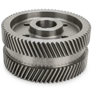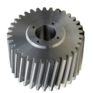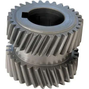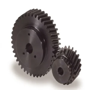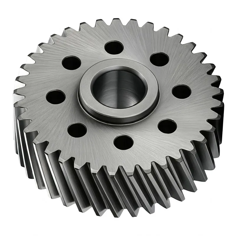
Engrenage hélicoïdal rectifié à bride EP-20CrMnTi
The EP-20CrMnTi Flange Ground Helical Gear is a precision-machined rotary transmission component engineered for applications where load capacity, positional accuracy, and long operational life must coexist in a compact drive assembly. Manufactured from 20CrMnTi chromium-manganese-titanium case-hardening steel and rated to DIN6 International Grade 5 accuracy, this helical gear is produced through a full gear-grinding final process that corrects heat-treatment distortion and achieves the tight tooth-profile and pitch tolerances demanded by servo-driven gearboxes, precision machine tools, and high-cycle industrial automation equipment.
The right-hand helix angle of 19°31’42” is the same geometry used throughout the EP helical gear and gear rack product family, meaning this helical gear meshes directly with the corresponding EP helical rack series for combined rotary-to-linear drive systems. Engineers designing helical rack and pinion drives — in gantry machines, portal CNC routers, or laser-cutting systems in Germany, Japan, Australia, and North America — can specify the rack and the helical pinion gear from the same product family to ensure tooth-geometry compatibility without additional design verification. The Module 2 standard across the YMCLK series allows straightforward inter-model substitution when tooth count is the only changing variable between application variants.
The series spans tooth counts from 26 to 37 in the standard YMCLK range and extends to 40 teeth in the YMCL series, covering a meaningful range of gear ratios and pitch-circle diameters within the Module 2 family. Bore diameters are standardised at 31.5 mm (H6 tolerance) for the shaft interface, and the flange outer diameter scales with tooth count across the range. All specifications shown in the tables below reflect the catalogue standard; non-standard tooth counts, modules, and bore geometries are available on drawing submission.
EP-20CrMnTi Flange Ground Helical Gear — Right-Hand Helix Angle 19°31'42"
DIN6 International Grade 5 · 20CrMnTi Alloy Steel · Overall Carburizing HRC55–60° · Gear Grinding · Flange-Mounted Design
Technical Specifications at a Glance
| Paramètre | Spécification |
|---|---|
| Accuracy Level | DIN6 International Grade 5 |
| Matériel | 20CrMnTi Alloy Steel (Case-Hardening Grade) |
| Tooth Profile | Helical teeth |
| Helix Angle | Right-hand 19°31'42" |
| Hardness Treatment | Overall carburizing HRC55–60° |
| Production Process | Gear grinding (after carburizing quench) |
| Module | 2 |
| Standard Bore (H6) | 31.500 mm |
| Flange Bolt-Circle Angle | 45° equally spaced |
Flange Outer Body Dimensions — YMCLK Series (Unit: mm)
All dimensions in millimetres. AH6 and BH6 are tolerance-class H6 bore and register fits.
| Code | Module | Tooth No. | AH6 | BH6 | C | D | E | F | G | H | je | J |
|---|---|---|---|---|---|---|---|---|---|---|---|---|
| YMCLK26 | 2 | 26 | 15 | 20 | 55.174 | 60.800 | 26 | 29.0 | 5.5 | 10 | 12 | 31.5 |
| YMCLK27 | 2 | 27 | 15 | 20 | 57.296 | 61.296 | 30 | 33.5 | 5.5 | 10 | 11 | 31.5 |
| YMCLK29 | 2 | 29 | 15 | 20 | 61.540 | 67.200 | 26 | 29.0 | 5.5 | 10 | 12 | 31.5 |
| YMCLK35 | 2 | 35 | 15 | 20 | 74.272 | 79.800 | 26 | 29.0 | 5.5 | 10 | 12 | 31.5 |
| YMCLK29-20 | 2 | 29 | 20 | 25 | 61.540 | 67.200 | 26 | 30.0 | 6.6 | 11 | 14 | 40 |
| YMCLK33 | 2 | 33 | 20 | 31.5 | 70.028 | 75.599 | 26 | 30.0 | 6.6 | 11 | 14 | 50 |
| YMCLK35 | 2 | 35 | 20 | 31.5 | 74.300 | 79.500 | 26 | 30 | 6.6 | 11 | 14 | 50 |
| YMCLK36 | 2 | 36 | 20 | 31.5 | 76.394 | 80.394 | 30 | 34.0 | 6.6 | 11 | 8 | 50 |
| YMCLK37 | 2 | 37 | 20 | 31.5 | 78.517 | 84.200 | 26 | 30.0 | 6.6 | 11 | 14 | 50 |
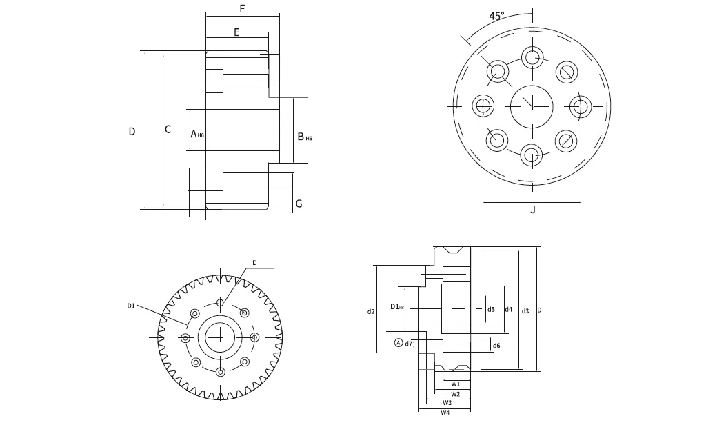
Shaft Bore & Keyway Dimensions — YMCL Series (Unit: mm)
| Code | Module | Tooth No. | d1H6 | d2 | d3 | d4 | d5 | d6 | d7 | W1 | W2 | W3 | W4 | DH6 | D1 |
|---|---|---|---|---|---|---|---|---|---|---|---|---|---|---|---|
| YMCL37 | 2 | 37 | 31.500 | 63 | 78.52 | 35 | 20 | 1.1 | 6.6 | 14 | 24 | 34 | 40 | 6 | 50 |
| YMCL40 | 2 | 40 | 31.500 | 63 | 84.88 | 35 | 21 | 1.1 | 6.4 | 14 | 26 | 31 | 37 | 6 | 50 |
All specifications subject to change without prior notice. Please confirm dimensional requirements before ordering. Non-standard configurations are available on drawing submission.
How a Flange-Mounted Helical Gear Works
UN helical gear transmits torque between parallel shafts through teeth that are cut at an angle to the rotation axis — in this case 19°31'42" to the right. Unlike spur gears, which engage all at once across the full tooth face, helical teeth enter contact progressively from one end of the tooth to the other. This gradual engagement means multiple tooth pairs share the transmitted load simultaneously at any instant, which has several measurable consequences: lower peak contact stress per tooth, significantly reduced operating noise, smoother torque transfer with less speed variation, and better tolerance of dynamic load spikes from the driven machine. The result is a gear type that is both stronger and quieter than an equivalent spur gear at the same module and pitch diameter — which is why the helical gear vs spur gear comparison almost always favours the helical type in precision and high-speed gearbox applications.
The flange body serves a structural purpose beyond mere axle support. The flanged outer ring — with its precisely bored central hub (d1H6) and 45°-spaced bolt holes — allows the gear to be located and clamped to a mating housing face without relying on interference fits alone. This makes the helical gear replaceable without disassembling the shaft or gearbox. In precision machine tool spindles and servo-driven transfer machines where gear wear is an expected maintenance item, flange-mount designs reduce downtime because the replacement procedure is a bolt-on operation rather than a press-fit overhaul. The DIN6 Grade 5 tooth accuracy maintained through gear grinding ensures that a replacement gear drops in without a tooth-mesh re-calibration cycle.

Cinq avantages clés en matière de performance
① DIN6 Grade 5 Gear-Ground Accuracy
Chaque helical gear in this series is finish-ground after carburizing quench, correcting the heat-treatment distortion that would otherwise degrade pitch and profile accuracy. The resulting DIN6 Grade 5 tolerance class ensures tooth-to-tooth error stays within limits that servo motion controllers can compensate for easily, giving repeatable positioning performance in precision helical gear drive trains used across European machine tool and semiconductor equipment sectors.
② 20CrMnTi Case-Hardened Core Toughness
20CrMnTi is specifically formulated for case-hardening applications. After carburizing to a case depth of approximately 0.8–1.2 mm, the surface reaches HRC55–60° while the core retains a tensile strength above 980 MPa. This combination makes the gear resistant to surface pitting — the dominant failure mode for high-cycle helical gear sets — while the tough core absorbs shock loads from sudden acceleration or load reversal without brittle fracture. It is a material choice made by helical gear manufacturers worldwide for automotive transmission and precision reducer applications.
③ Smooth, Low-Noise Helical Tooth Engagement
The 19°31'42" helix is consistent across the full EP helical gear series and the matching helical rack range, enabling drive systems to be assembled from pre-matched components without helix-angle mismatch concerns. Progressive tooth engagement — the defining characteristic of helical spiral gear designs — keeps contact ratio above 1.5 at all times, substantially reducing the cyclic noise and vibration that straight-cut gears generate, a critical factor for gearboxes mounted near precision measurement or inspection systems.
④ Flange Body for Fast, Reliable Installation
The integrated flange with 45°-spaced bolt holes allows the helical gear to be located and secured to a housing face in a single operation, with no requirement for a separate hub or locking collar. The H6 tolerance on both the central bore and the flange register diameter ensures a controlled interference or transition fit to the mating shaft and housing simultaneously, eliminating the runout error that can accumulate when three separate parts — gear blank, hub, and housing — are individually fitted in the field.
⑤ Family Compatibility with EP Helical Rack Series
The 19°31'42" right-hand helix and Module 2 standard match exactly to the EP helical rack family, making this gear the natural helical pinion gear for helical rack and pinion drive systems. Designers of gantry machines, automated dispensing systems, and linear axis drives in Canada, the Netherlands, South Korea, and Australia can specify both the rack and the helical gear pinion from the same product family — verified compatible geometry, single procurement source, consistent quality documentation.
Material & Heat Treatment
20CrMnTi is a chromium-manganese-titanium low-alloy case-hardening steel that has been the material of choice for automotive transmission gears, differential pinions, and precision speed reducer gears in Asia and Europe for decades. The titanium addition refines the austenite grain during carburizing, which prevents the grain growth that would otherwise coarsen the case microstructure and reduce contact fatigue life. Compared to plain carbon steels, 20CrMnTi achieves a deeper, more uniform carburized case in shorter cycle times, and its core hardenability ensures that the sub-case region retains adequate yield strength to support the hardened case under Hertzian contact loading. This is a material-selection consideration that separates purpose-built helical gear products from general-purpose pinion stock.
The heat treatment sequence — carburizing at 920–940°C, followed by direct quenching or re-quenching, and a final low-temperature temper at 150–200°C — drives the case hardness to HRC55–60° as specified. Post-quench gear grinding then removes the outer decarburized or distorted surface layer from the tooth flanks, exposing the fully hardened case beneath and correcting tooth geometry to DIN6 Grade 5. The combination of through-grain control from titanium alloying, deep uniform case from the controlled atmosphere furnace, and final ground tooth geometry defines a helical gearset that is genuinely engineered rather than merely produced — a distinction that users in precision manufacturing industries in Japan, Taiwan, and Germany recognise immediately from the dimensional consistency of the delivered parts.

Scénarios d'application
Precision CNC Machine Tool Spindles
High-speed spindle gearboxes on CNC machining centres and grinding machines require helical gears that transmit power smoothly without the torsional impulses that lead to chatter marks on the workpiece surface. The DIN6 grade and HRC55–60° case-hardened tooth surface of this series meets the accuracy and durability requirements of spindle transmission gears used in machine tools manufactured across Germany, Japan, and Taiwan.
Servo-Driven Helical Gear Reducer
Compact servo helical gear reducer assemblies — used in robotics end effectors, AGV steering drives, and automated assembly jigs — demand the highest combination of tooth accuracy and surface hardness to achieve the backlash and rigidity specifications their servo controllers require. This flange helical gear integrates cleanly into such reducers, with the flange body providing the locating register that holds the gear centred under load without fretting wear.
Helical Rack and Pinion Gantry Drives
When paired with the matching EP helical rack, this gear operates as the helical pinion gear in portal gantry axes for laser cutters, plasma tables, and pick-and-place gantries deployed in Australian, Dutch, and South Korean industrial facilities. The 19°31'42" helix compatibility with the rack series means the gear drop-in replaces a worn pinion without helix-angle recalculation, reducing field maintenance time significantly on long-running production machines.
Printing & Packaging Transfer Drives
Web-fed printing presses and horizontal form-fill-seal packaging machines use helical gear sets in their main transfer drives because progressive tooth contact suppresses the torsional oscillation that causes print banding or packaging film registration errors. The noise reduction from helical engagement is a secondary benefit in machinery installed near production workers — a compliance factor in Canadian and UK workplace noise regulation that plant engineers factor into gearbox selection.
Parallel Shaft Gearbox Stages
Multi-stage helical gear sets are the foundation of efficient parallel shaft gearboxes used in conveyor drives, fan drives, and mixers across heavy industry in Brazil, Colombia, and the UK. The high tooth-surface hardness of this series ensures that each gear stage contributes years of service before tooth flank wear accumulates to the point of backlash growth — a critical performance parameter in position-sensitive conveyor indexing systems.
Medical & Laboratory Positioning Stages
CT scanner tables, ophthalmic laser platforms, and laboratory liquid-handling gantries demand helical gears that produce minimal audible noise and no perceptible vibration during movement. The smooth engagement of this helical gear type, combined with the DIN6 pitch accuracy that keeps velocity variation low across each tooth cycle, makes it a natural fit for medical device drive trains in UK and German hospital-equipment manufacturing, where acoustic output is a regulatory criterion alongside positional accuracy.
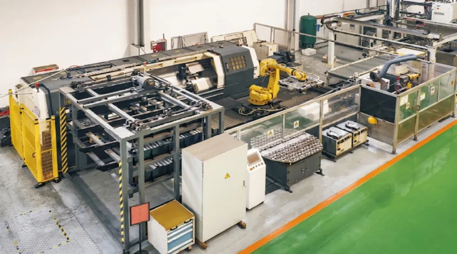
About Our Factory
Our production operation has built up more than ten years of concentrated expertise in mechanical power transmission manufacturing, with a particular depth in precision gear products — from standard catalogue helical gears through to custom-profiled gear sets produced to OEM engineering drawings. Certifié ISO 9001:2015, we operate documented process controls from raw material incoming inspection through carburizing furnace cycle management, gear grinding, and final gear-accuracy verification on gear-measurement centres traceable to national standards.
Our manufacturing range covers agricultural gearboxes, worm gear speed reducers, planetary gear drives, PTO shafts, hydraulic cylinders, roller chains, and electric motors. We also produce a comprehensive range of gearbox housings in ductile iron, cast iron, cast steel, precision investment-cast steel, and die-cast aluminium, together with sprockets, worm wheels, pulleys, worms, shafts, and both standard and non-standard mechanical components. Whether you need off-the-shelf helical gears from the catalogue or a fully engineered custom helical gearset for a dedicated parallel shaft gearbox design, our engineering and production teams can support the complete development and supply cycle.
Atelier



Produits associés
Helical Gear Series
Beyond this flange-mount variant, our complete helical gear range includes shaft-mount, hub-mount, and custom-profile configurations across a broad module and tooth-count selection. Sourcing your complete helical gearset from a single manufacturer ensures that helix angle, tooth form, and material specification are consistent across every stage — an important factor in gearbox efficiency calculation and noise prediction. Our helical gear suppliers team can advise on matching configurations for your specific gear ratio requirement.

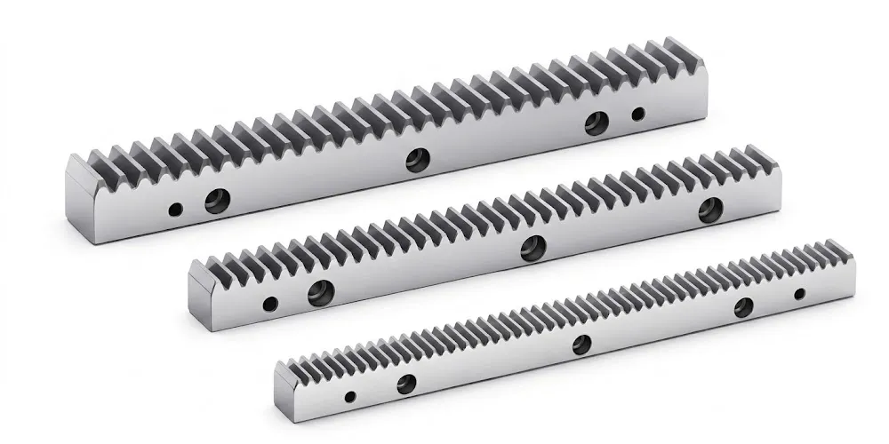
Crémaillère à engrenages hélicoïdaux
The matching gear rack series shares the same 19°31'42" helix angle and Module 2 standard as this helical gear, making them geometrically pre-verified as a helical rack and pinion pair. For linear drive systems — CNC gantry axes, laser-cutting bridges, or automated storage traversers — specifying both the rack and the helical pinion gear from the same production facility eliminates the tooth-form mismatch risk that arises when sourcing rotary and linear elements from separate vendors with different gear standards.
Foire aux questions
Éditeur : PXY