
AUTOMOTIVE & HEAVY EQUIPMENT — APPLICATION INSIGHT
Automotive paint and body shops run overhead power-and-free conveyors around the clock. This guide examines why a worm gear single speed reducer remains the most practical drive selection for these demanding continuous-duty environments — covering mechanical principles, material construction, selection parameters, maintenance practice, and compatible products for global OEM procurement.
Worm Gear Reducer
Automotive Paint Shop
Overhead Conveyor
Continuous Duty
The Overhead Conveyor Environment in Automotive Finishing
Paint shop and body shop operations in automotive plants represent some of the most mechanically demanding environments for drive equipment anywhere in manufacturing. Overhead power-and-free conveyor systems carry vehicle bodies — or body-in-white structures — through pre-treatment baths, electrocoat dip tanks, primer spray booths, base coat and clear coat application zones, and curing ovens that routinely operate at 160–200°C. The conveyor itself runs continuously, often 20 or more hours per day across multiple shifts, with drives that must maintain precise, low chain speed while delivering consistent torque against the combined weight of the carrier, the vehicle body, and any accumulated drag from guide rails and chain lubricant.
The drive station for a paint shop overhead conveyor typically sits at a point where horizontal chain tension must be converted into controlled pull through the loop. A single speed reducer — specifically, a right-angle worm gear speed reducer worm gearbox — fills this role because it simultaneously provides the speed reduction ratio needed to bring a standard motor speed (typically 1400–1450 RPM at 50 Hz, or 1700–1750 RPM at 60 Hz) down to a chain drive speed of 6–18 RPM, and because the worm gear geometry inherently prevents back-driving when the motor is de-energized, holding the loaded conveyor chain stationary without a secondary brake.
Automotive plants in Germany, the USA, South Korea, Brazil, Mexico, and Japan all operate overhead conveyor systems of broadly similar architecture. The dimensional and performance requirements for drive reducers in these facilities are well-standardized, which is why the single stage speed reducer families used in European VW Group plants are dimensionally interchangeable with those used in North American and Asian assembly facilities — as long as the center distance, ratio, shaft diameter, and mounting configuration are correctly specified.

Why a Single Speed Reducer Is Specified for Paint Shop Drives
The worm gear single speed reducer has been the dominant drive type in paint shop overhead conveyor applications for several practical reasons that have proved durable across decades of automotive production evolution. At the ratios used in conveyor drives — typically 1/20 through 1/60 — a single reduction worm reducer achieves the necessary speed drop in one gear mesh stage, keeping the gearbox compact and the maintenance item count low. There is no intermediate shaft, no additional bearing set, and no secondary gear stage that could wear independently and create diagnostic complexity.
The right-angle shaft arrangement of a single stage right-angle worm-gear speed reducer is the other critical advantage. Paint shop conveyors typically drive a caterpillar-type drive unit or a drive sprocket positioned at the top of a vertical drop section. The motor must attach horizontally or vertically to the conveyor’s structural steelwork, while the output shaft connects to the drive sprocket or chain dog. A right-angle worm speed reducer handles this geometry directly — no additional bevel stage or right-angle adapter is required, reducing the overall drive package depth and weight at each drive station.
Self-locking is the third defining characteristic. At reduction ratios of 1/30 and above, the lead angle of the worm thread is shallow enough that back-drive from the loaded chain cannot overcome the friction in the gear mesh. This means the conveyor chain holds its position when the motor is switched off — a safety-critical property in paint shop environments where uncontrolled load movement would swing vehicle bodies through spray booths and cause significant damage. In facilities across Germany, South Korea, and the USA, this inherent mechanical holding function removes the need for motor-integrated holding brakes on most non-emergency conveyor sections.
Structure de fabrication
The reducer housing is cast from HT200 grey cast iron, a material valued in overhead conveyor drive applications for its rigidity and vibration damping. Paint shop ovens create thermally cyclic conditions — the drive unit heats and cools through each production cycle — and grey cast iron’s coefficient of thermal expansion and mechanical damping characteristics make it more suitable than aluminium for this environment. Bearing bore diameters are finish-machined to H7 tolerance to maintain bearing position accuracy over the thermal cycles experienced in oven-proximity drive stations. The housing base or flange mounting face is machined flat to within 0.05 mm to ensure secure, rattle-free attachment to conveyor structural steelwork.
The worm shaft is forged from 20CrMnTi alloy steel, carburized to a case depth matched to the rated contact load, then hardened to 58–62 HRC at the thread surface. Thread grinding is performed after the full heat treatment cycle to remove distortion introduced by carburising. This post-grind sequence is the production step that separates a premium worm reducer from lower-grade units: distorted thread geometry from pre-grind-only manufacture leads to poor mesh contact, accelerated worm wheel wear, and elevated operating temperature — problems that emerge after several months of continuous duty in a paint shop conveyor drive and are expensive to diagnose and correct once the drive station is embedded in the conveyor structure.
The worm wheel is centrifugally cast from ZCuSn10Pb1 tin phosphor bronze, finish-hobbed to the correct module and pressure angle after casting. Phosphor bronze is chosen for its tribological compatibility with the hardened steel worm — the relatively softer bronze creates a controlled bedding-in process that improves mesh contact geometry over early operating hours, while the tin and lead content provides the boundary lubrication reserve needed when the oil film is momentarily insufficient during load transients. For overhead conveyor drives in paint shops where the worm gear reducer installation is typically at or above floor level, the wheel’s oil-bath contact arc is confirmed against mounting orientation to ensure adequate lubrication across all operating positions.
Input shaft bearings are deep-groove ball type, sized for the combined radial and thrust loads from the worm thread. Output shaft bearings are tapered roller type, selected to handle the large axial component generated by the worm wheel mesh. Double-lip nitrile rubber (NBR) oil seals at all shaft exits provide the dual containment needed in paint shop environments where paint mist, solvent vapour, and oven exhaust gases are present. The breather vent is positioned and sized to equalize internal pressure without permitting contaminated air from the surrounding environment to enter the housing — a detail that matters in phosphate pretreatment zones where the air carries corrosive acids.
Système de matériaux
The material selection for a single speed reducer deployed in a paint shop overhead conveyor drive reflects two competing requirements: the mechanical load capacity needed for continuous-duty chain pull, and the thermal and chemical resistance needed to survive proximity to oven exhaust, pretreatment chemistry, and paint overspray. Each component in the WP-series worm gear reducer gearbox addresses both requirements.
Housing surfaces exposed to chemical environments in pretreatment zones are protected by alkyd-based paint systems applied over a zinc-phosphate conversion coating on the cast iron substrate. For facilities specifying reducers for positions inside or immediately adjacent to electrocoat tanks — common in Korean and Japanese plants where the e-coat line is more compact — additional epoxy topcoat is specified to resist the ammonium-based e-coat bath chemistry.
| Composant | Matériel | Specification / Treatment | Relevance to Paint Shop Duty |
|---|---|---|---|
| Logement | HT200 Grey Cast Iron | CNC-machined bearing bores, H7 tolerance | Rigid, thermally stable, vibration-damping under variable oven cycle loading |
| Arbre à vis sans fin | Acier allié 20CrMnTi | Carburized, hardened 58–62 HRC, post-grind thread form | Wear-resistant thread surface sustains continuous-duty mesh without progressive profile loss |
| Roue à vis sans fin | ZCuSn10Pb1 Phosphor Bronze | Centrifugally cast, finish-hobbed | Controlled bedding-in; boundary lubrication reserve under load transients from conveyor chain tension variation |
| Input Bearings | Deep-groove Ball Bearing | ISO grade, grease-packed with sealed shield option | Handles radial and thrust load from worm at continuous motor speed |
| Output Bearings | Tapered Roller Bearing | Adjustable preload, ISO tolerance class | Manages large axial force component from worm wheel engagement; maintains shaft position under chain pull load |
| Joints d'arbre | Nitrile Rubber (NBR) | Double-lip, spring-loaded | Retains oil in chemically active paint shop atmosphere; resists mineral gear oil, phosphate bath splash |
| Lubrifiant | ISO VG 220 Mineral Gear Oil (standard) | Synthetic PAO option for oven-proximity units | Maintains viscosity across oven proximity temperature range 40–80°C ambient; extended intervals with PAO grade |

Selecting the Right Single Speed Reducer for Paint Shop Conveyor Duty
Specifying a single speed gear reducer for a paint shop overhead conveyor drive involves working through a defined sequence of parameters, starting with the conveyor’s chain pull and chain speed requirements. Because the worm gear reduction ratio directly controls both the output speed and the output torque, the ratio is the first calculated value — not a catalogue assumption. For a conveyor chain moving at 10 m/min with a 250 mm drive sprocket pitch diameter (giving an output shaft speed of approximately 12.7 RPM), a 1450 RPM motor requires a reduction ratio of approximately 1/114 — achievable only with a double-stage worm gear reducer. At 6 m/min chain speed with the same sprocket, the required output speed is 7.6 RPM, requiring a 1/191 ratio — again, double stage. At more typical 3–4 m/min conveyor speeds with smaller sprockets, the single stage ratios of 1/40 to 1/60 become appropriate.
Service factor selection is the step most frequently handled incorrectly on conveyor drive specifications. Overhead power-and-free conveyors experience load surges when chains accumulate slack at buffer zones and then pull taut against accumulated carriers. An appropriate service factor for this shock loading pattern is 1.5–1.75 applied to the calculated steady-state torque requirement, before comparing against the single speed worm reducer’s rated output torque. Applying a service factor of only 1.0 or 1.25 — common when the conveyor designer relies only on steady-state chain pull calculations — leads to premature worm wheel wear at buffer zones and in facilities where chain lubrication is insufficient to prevent stick-slip at startup.
| Selection Parameter | Typical Paint Shop Value | Design Impact |
|---|---|---|
| Required output speed | 7–25 RPM | Sets reduction ratio; drives frame size selection |
| Motor speed (50 Hz) | 1400–1450 RPM (4-pole) | Reference for ratio calculation; VFD-driven motors may vary |
| Chain pull (steady state) | 800–4,000 N depending on body weight and conveyor length | Combined with sprocket radius determines output torque requirement |
| Service factor | 1.5–1.75 (shock/buffer loading) | Applied to torque requirement before frame size confirmation |
| Thermal ambient | 40–80°C (oven proximity) | May require synthetic lubricant or derated thermal power rating |
| Mounting orientation | Input horizontal, output horizontal or downward | Controls oil fill level position; confirm with shaft direction variant code |
| Duty cycle | Continuous (S1) — 20+ hours/day | No cyclic thermal relief; thermal power rating must cover full S1 load without derating |
Recommended Products for Paint Shop Overhead Conveyor Drives
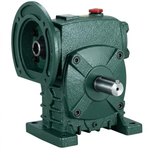
The EP-WPDS is a foot-mounted, flange-compatible worm gear single speed reducer with hardened tooth surface and a reduction ratio range of 1/5 through 1/60. Its input power range of 0.12 to 15 kW covers the motor sizes used in virtually all paint shop overhead conveyor drive stations — from small zone drives running 0.37 kW motors through to main line drives at 7.5–11 kW. The WPDS designation indicates a solid output shaft configuration with a standard keyway, suitable for direct coupling to drive sprockets via a rigid or semi-rigid hub.
For continuous-duty S1 service in automotive paint shops in Germany, the USA, South Korea, and Brazil, the EP-WPDS is typically selected at frame sizes 100–175 (center distance) with 1/40 or 1/50 ratios, producing output torques that match the chain pull requirements of most body-in-white conveyor systems handling vehicle bodies in the 400–600 kg loaded carrier weight range.
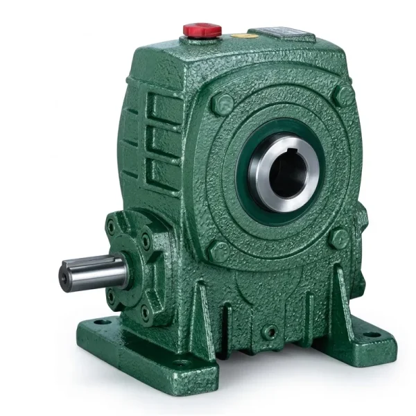
The EP-WPKA is a hollow-bore output single speed reducer, accepting the driven shaft directly through the output hub and eliminating the need for a projecting output shaft and separate coupling. This configuration is well-suited to conveyor drive stations where the drive sprocket shaft passes through the gearbox output hub — common in accumulating-type paint shop conveyors where the drive dog engages the chain from a shaft that traverses the entire drive station width. The unit weight range of 5 to 260 kg across frame sizes reflects the full range from small auxiliary zone drives up to main-line heavy-duty units.
For facilities in Japan and South Korea operating high-density shuttle conveyor systems with limited drive station footprint, the WPKA hollow-bore configuration eliminates the coupling overhang that would otherwise require additional clearance in the overhead steelwork envelope.
Installation and Maintenance in Automotive Paint Shop Conditions
Correct installation of a worm gear speed reducer worm gearbox in an overhead conveyor drive station requires attention to several details that are specific to the automotive paint shop environment. The reducer must be mounted on a rigid steel bracket welded or bolted to the conveyor’s overhead steelwork, with all four mounting feet in simultaneous contact with the bracket face before any bolts are tightened. Shimming any gap before final tightening prevents housing distortion that would misalign bearing bores and accelerate bearing wear — a failure mode that typically appears after 6–12 months in continuous S1 service.
Shaft alignment between the motor and the reducer input follows standard flexible coupling tolerance limits. For motor-flange (D-type) units where the motor attaches directly to the reducer input face, the pilot circle fit between motor register and reducer bore must be within the tolerance specified on the dimensional drawing — typically H7/g6 clearance fit. Misalignment at this interface creates a bending moment on the worm shaft, which transfers directly into the input bearing as additional axial load and reduces bearing life significantly.
Oil change intervals for paint shop duty depend on the thermal environment of the drive station. At normal conveyor drive positions remote from oven zones, ISO VG 220 mineral gear oil requires a first change at 200–300 operating hours (to remove bedding-in metal particles), then annually or at 3,000 hours thereafter. For drive stations within 2–3 metres of oven entry or exit sections — where ambient temperature regularly exceeds 60°C — the change interval shortens to 1,500 hours with mineral oil, or alternatively, a switch to synthetic PAO-based ISO VG 220 gear oil extends the interval to 5,000 hours and improves load-film thickness at elevated temperature. Automotive plants in Germany and the Netherlands commonly specify PAO lubricant as standard for all oven-zone conveyor drives as part of their predictive maintenance programs.

Common Fault Patterns in Paint Shop Conveyor Drives and Their Causes
Most frequently caused by overloading beyond the thermal power rating, oil level errors (too high creates churning heat; too low starves the mesh), or contaminated gear oil that has degraded past its useful viscosity range. In paint shop environments, check first that the oven-zone ambient temperature is not pushing the reducer beyond its thermal derating curve before attributing the issue to internal causes.
The most common maintenance action on paint shop overhead conveyor reducers, because seal lip wear accumulates steadily in the chemically active environment. Paint particles and phosphate bath residue abrade the seal lip over time. Shaft surface scoring at the seal seat — from prior seal failure — prevents the replacement seal from seating properly and must be addressed before re-sealing. Over-filling the reducer is the most easily corrected cause: check the oil level against the gauge mark for the actual mounting orientation.
Worm gear reducers on overhead conveyors that develop a periodic clunking or grinding noise at the output shaft frequency are typically showing early bearing wear or worm wheel tooth pitting — both consequences of prolonged operation with degraded lubricant or with occasional overload from buffer zone chain surges. Diagnosis begins with checking the oil condition and level, then listening for the noise frequency relative to output shaft rotation versus input motor speed to identify which component is generating the disturbance.
When a worm wheel shows visible tooth face scoring or unusual material transfer to the worm thread within the first year of S1 operation, the cause is almost always one of: under-specification of frame size relative to actual service torque, incorrect oil grade, insufficient initial oil-change interval (missed 200-hour first change), or operating temperature consistently above 80°C at the housing surface. Each root cause requires a different corrective action — resizing, relubrication, schedule adjustment, or repositioning of the drive station relative to oven exhaust, respectively.
Compatible Products for Complete Conveyor Drive Systems
A paint shop overhead conveyor drive system requires more than a single speed reducer in isolation. The following compatible products support complete drive system procurement from a single source, eliminating inter-supplier compatibility risk on motor-gearbox interfaces and chain drive components.
Matching a single speed reducer with a correctly flanged electric motor eliminates the shaft coupling alignment step and reduces drive station assembly time. IEC B5 and B14 flange motors sized from 0.12 kW to 15 kW pair directly with WP-series single speed reducers via standard pilot circle and bolt pattern dimensions. For variable-speed paint shop conveyors with VFD control — increasingly common in German and Japanese plants to enable zone-speed adjustment — confirm the motor’s VFD-compatible winding insulation rating before pairing with the inverter system.

Beyond the réducteur à vitesse unique series, the full worm gearbox range covers double-stage and universal-type configurations for applications where a single stage ratio is insufficient — such as very slow-speed accumulation zones or precision indexing stations within the paint shop. The WP series and NMRV compact units also serve ancillary conveyor functions including vent opening mechanisms, panel positioners, and chemical bath agitators. Sourcing the complete range from one manufacturer simplifies spares management and ensures dimensional interchangeability across retrofit and expansion projects.

À propos de notre usine de fabrication
Our manufacturing facility produces a broad range of industrial power transmission components, including worm gear reducers, agricultural gearboxes, planetary drives, power take-off shafts, hydraulic cylinders, gears, chains, and electric motors — all under a single ISO 9001:2015 certified quality management system. With over 20 years of production experience, our engineering team designs and manufactures gearboxes and assemblies in ductile iron, cast iron, cast steel, precision cast steel, and cast aluminium to meet OEM and standard dimensional requirements across multiple international standards — DIN, ISO, ANSI, JIS, and AGMA.
All gear cutting, heat treatment, CNC grinding, assembly, and outgoing inspection are performed in-house, giving us complete material traceability from raw casting to finished worm gear speed reducer unit. Our product range serves customers in North America, Europe (Germany, Italy, Poland, Spain), South America (Brazil, Colombia, Argentina), the Middle East, Southeast Asia, and Australia — including automotive OEM supply chains, industrial equipment manufacturers, and aftermarket replacement programs.
Custom single speed reducer specifications — including modified shaft dimensions, non-standard ratios, private-label packaging, and STEP file provision for integration CAD — are available for volume OEM programs. Technical support for motor-gearbox sizing, thermal rating verification, and mounting orientation review is provided as a standard service alongside product supply.
Atelier




Foire aux questions
Q1. What type of single speed reducer is most suitable for continuous-duty overhead conveyor drives in a German automotive paint shop operating at 20+ hours per day?
For continuous S1 duty in a German automotive paint shop, the right-angle worm gear single speed reducer in the WP series — specifically the WPDS foot-and-flange-mount configuration — is the most practical selection. Key criteria: the frame size must be confirmed against both the mechanical output torque requirement (including a 1.5–1.75 service factor for buffer zone shock loading) and the thermal power rating for the actual ambient temperature at the drive station position. For drive stations within oven proximity zones regularly exceeding 60°C ambient, synthetic PAO ISO VG 220 gear oil is specified over standard mineral grade, and the thermal rating must be confirmed at the elevated ambient rather than at the standard 25°C reference. Motor-flange input variants eliminate the coupling alignment step and are preferred in high-density conveyor layouts where drive station footprint is constrained by overhead steelwork spacing.
Q2. How do I calculate the correct worm gear reduction ratio for a paint shop overhead conveyor drive running at 8 metres per minute chain speed in a South Korean automotive assembly plant?
To find the required ratio, first determine the output shaft speed in RPM from the chain speed and drive sprocket dimensions. For a standard 200 mm pitch-circle-diameter drive sprocket at 8 m/min chain speed, the output shaft speed is approximately 12.7 RPM (8,000 mm/min divided by 200 mm × pi = 12.73 RPM). With a standard 4-pole 60 Hz motor at 1750 RPM input, the ratio required is 1750 / 12.73 = approximately 1/137 — this requires a double-stage worm reducer rather than a single stage unit. At 50 Hz (1450 RPM motor), the calculation gives 1450 / 12.73 = approximately 1/114, again requiring double stage. For single stage worm gear reducers (1/5 to 1/60 range), the chain speed must be at or above approximately 3–4 m/min with typical sprocket sizes used in South Korean overhead conveyor systems, or the sprocket diameter must be significantly larger than 200 mm to bring the ratio into single-stage range.
Which single speed reducer oil grade should I use for a body shop overhead conveyor drive station positioned near a curing oven in a Brazilian automotive plant running two-shift operations?
For a drive station near a curing oven in Brazil — where the combination of high ambient temperature and two-shift continuous operation creates an elevated thermal load on the reducer — the oil selection should be based on the actual housing surface temperature during steady-state operation rather than the nominal ambient. If the housing surface runs consistently above 60°C, ISO VG 220 synthetic PAO gear oil is the appropriate selection: it maintains its viscosity index across a wider temperature range than mineral oil, provides better load film at elevated temperature, and extends the change interval from the 3,000-hour mineral oil standard to approximately 5,000 hours. This extended interval reduces maintenance interventions on overhead-mounted drive units that require platform access for servicing — a practical benefit in Brazilian plants operating two-shift 16-hour production schedules where maintenance windows are limited.
Q4. Where can OEM plant engineers in the USA find a customized single speed reducer manufacturer that supplies worm gear drives sized specifically for paint shop overhead conveyor applications with hollow-bore output shafts?
OEM plant engineers in the USA sourcing customized single speed reducers for paint shop overhead conveyor applications should look for manufacturers who can demonstrate in-house worm thread grinding (post-heat-treatment), ISO 9001:2015 certification, and the ability to supply both standard catalogue and modified-specification units from the same production line. Key customization points for hollow-bore configurations include output bore diameter and tolerance to suit the conveyor sprocket shaft, keyway profile, and torque arm mounting arrangement. Requesting STEP file data for the hollow-bore output side during the specification phase allows the conveyor design team to verify clearances in the overhead steelwork model before committing to a unit. Manufacturers offering engineering review of the application — rather than just catalogue selection — are more reliable partners for conveyor drive procurement in automotive paint shop environments where downtime consequences are significant.
Q5. When is a worm gear single speed reducer more appropriate than a helical bevel reducer for driving the main chain in an automotive body shop overhead conveyor system in Japan?
A worm gear single speed reducer is more appropriate than a helical bevel unit for the main overhead conveyor chain drive in a Japanese body shop when three conditions align. First, the required reduction ratio falls in the 1/20 to 1/60 range, where a single worm stage achieves the full reduction compactly while a helical bevel unit would require two stages and a larger installation envelope in the overhead steelwork. Second, load-holding without a powered brake is required — the worm gear’s self-locking property at ratios of 1/30 and above keeps the loaded chain stationary when the motor is de-energized, which is a code-required safety function in Japanese automotive plant overhead conveyor systems under JISB8810 provisions. Third, where noise is less critical than in a clean-room environment, the moderate noise level of worm gear drives is acceptable, and the cost advantage over equivalent helical bevel units — which use more expensive gear geometry and manufacturing processes — is a factor in the total drive system budget for a paint shop that may have 40–80 individual drive stations along a single production loop.
Éditeur : PXY