
AUTOMOTIVE & HEAVY EQUIPMENT — APPLICATION INSIGHT
Utilisation des réducteurs à une seule vitesse dans les bancs d'essai de transmission finale des trains de roulement d'engins lourds
Undercarriage final drive assemblies for excavators, bulldozers, and crawler cranes undergo rigorous end-of-line torque and speed verification before installation. This guide examines how a single speed reducer functions as the load-application and speed-control element within final drive test stands — covering mechanical principles, manufacturing construction, material selection, test parameters, and product recommendations for global heavy equipment manufacturers and testing integrators.
Final Drive Test Stand
Heavy Equipment Undercarriage
Worm Gear Reducer
Continuous Duty Drive
What Is a Final Drive Test Stand and Why Does It Matter?
A final drive test stand is a purpose-built rig used to verify the performance, efficiency, noise signature, and leak-tightness of planetary reduction assemblies before they are installed in crawler-type heavy equipment. Excavators manufactured in Japan, Germany, South Korea, the USA, and Brazil each carry a final drive unit at the rear of each track frame — a multi-stage planetary gearbox that converts the relatively high-speed, low-torque output of a hydraulic motor into the slow, high-torque rotation needed to move the crawler track at 2–5 km/h under the full weight of the machine.
End-of-line testing of these planetary assemblies is non-negotiable for Tier 1 heavy equipment OEMs. A final drive that leaves the assembly line with incorrect mesh pre-load, inadequate oil fill, or a damaged planet gear will fail in the field under the combined load of machine weight and ground reaction force — causing unplanned downtime in mining and construction operations where daily lost production costs are measured in thousands of dollars. The test stand applies controlled input speed and output load to the assembled final drive, records torque, temperature, and noise at defined operating points, and flags units outside acceptance limits before they reach the track frame assembly station.
The drive train of a final drive test stand itself requires careful engineering. It must apply a specific, stable input speed to the final drive’s hydraulic motor port (or mechanical input shaft on some designs), while simultaneously applying a controlled resistive torque to the output sprocket. A single speed reducer is commonly used in the drive-side of the test stand as the precision speed-reduction element between the test motor and the final drive input — providing the ratio needed to bring the test motor’s operating speed range into alignment with the final drive’s intended input speed window, typically 200–800 RPM depending on the machine class under test.

The Role of a Single Speed Reducer in the Test Stand Drive Train
Within a final drive test stand, the single speed reducer occupies a position between the primary test motor and the final drive unit under test. The test motor — typically a variable-frequency controlled induction motor sized from 7.5 kW to 75 kW depending on the excavator class — runs at speeds between 700 and 1450 RPM during the test cycle. The final drive’s input shaft, however, must be driven at a significantly lower speed: 200–600 RPM for mid-size excavator final drives, and as low as 50–150 RPM for large mining excavator or bulldozer planetary assemblies with higher internal reduction ratios.
A single stage right-angle worm-gear speed reducer bridging the test motor output and the final drive input provides this speed step-down in a single, compact drive element. The worm gear reduction ratio — typically selected from the 1/5 to 1/20 range for test stand applications, where the final drive’s own internal ratio provides additional reduction — drops the motor shaft speed to the final drive input speed range. The right-angle output shaft orientation is particularly practical in test stand design: the test motor is usually mounted horizontally at one end of the stand frame, while the final drive input port faces upward or to the side. A single speed gear reducer with right-angle output eliminates the need for a secondary bevel stage or angled coupling to redirect the shaft.
For test stands designed to evaluate both mechanical and hydraulic final drives — common in Japanese and German OEM facilities that produce multiple machine lines on shared test equipment — the single speed worm reducer’s interchangeable shaft configuration (variants A through F in the WP series) allows a single test stand frame to accommodate different drive orientations by swapping the reducer shaft direction code rather than rebuilding the entire drive train. This configurability reduces tooling investment for OEM test equipment integrators and shortens changeover time when switching between machine models on a shared test line.
Structure de fabrication
Test stand reducers are subjected to repeated start-stop cycles, speed ramps, and directional reversals across multiple test sequences per shift. The HT200 grey cast iron housing used in the WP series provides the structural stiffness needed to maintain bearing bore alignment through these dynamic loading cycles without fatigue cracking or housing distortion. The monolithic casting design — a single-piece housing rather than a split or bolted assembly — is the preferred specification for test stand applications because it eliminates parting-line oil leakage paths that would contaminate the test stand floor and invalidate leak tests on the final drive unit under test.
For test stand service, the worm shaft thread profile accuracy is more critical than in standard conveyor or machine drive applications. Speed stability at the final drive input port is directly dependent on the quality of the worm mesh — thread pitch errors translate into cyclical velocity variation at the output shaft, which in turn produces false torque ripple readings in the test data acquisition system. WP series worm shafts are ground after the full heat treatment cycle on CNC gear-grinding equipment, achieving thread pitch accuracy that keeps velocity variation below the threshold detectable by typical test stand torque measurement channels.
Phosphor bronze worm wheels in test stand reducers accumulate more start-stop and reversal cycles per unit time than wheels in production machine drives. The ZCuSn10Pb1 bronze alloy’s combination of tin for load capacity and lead for boundary lubrication reserve makes it the material of choice for this duty. Centrifugal casting produces a denser bronze ring with fewer voids than static casting — relevant in test stand service because void-originated fatigue crack initiation at the tooth root is the dominant failure mode for worm wheels that experience repeated load direction reversals during test cycle changes.
Test stand environments combine hydraulic fluid mist from final drive leak tests, gear oil from the reducer itself, and compressed air from pneumatic clamping fixtures. Double-lip NBR oil seals at all shaft exits provide containment against this mixed contamination environment. The breather vent is specified with a sintered stainless filter element rather than a simple cap, preventing pressure build-up during extended test sequences while excluding fine metal particles from final drive machining operations that circulate in test cell air. For test stands in facilities handling large mining excavator final drives — common in Australia, Chile, and South Africa — an additional labyrinth seal on the output shaft provides a first barrier against abrasive dust ingress before the lip seal contact zone.
Système de matériaux
Material selection for single speed reducers deployed in final drive test stands must satisfy two sets of requirements simultaneously: the mechanical requirements imposed by the torque and speed loading of the test cycle, and the environmental requirements of the test cell — which typically includes hydraulic fluid exposure, temperature variation from cold-start to full-load warm condition, and intermittent water exposure from final drive washing stations adjacent to test equipment in Korean, German, and Japanese OEM facilities.
The complete material system — from housing casting to lubricant specification — is aligned in the WP series to address these combined demands, with options for elevated duty cycles in mining equipment OEM test facilities where test stand utilisation can exceed 18 hours per day.
| Composant | Material Grade | Key Treatment | Relevance to Test Stand Duty |
|---|---|---|---|
| Logement | HT200 Grey Cast Iron | CNC-machined bores, H7 tolerance; zinc-phosphate + alkyd coating | Vibration damping under load cycling; corrosion resistance against hydraulic fluid splash in test cells |
| Arbre à vis sans fin | Acier allié 20CrMnTi | Carburized, 58–62 HRC, thread-ground post heat treatment | Stable thread pitch accuracy supports low velocity variation critical for test data integrity |
| Roue à vis sans fin | ZCuSn10Pb1 Phosphor Bronze | Centrifugally cast bronze ring on steel spider hub; finish-hobbed | Dense casting structure resists fatigue crack initiation under repeated load-direction reversals during test cycle changes |
| Input Bearings | Deep-groove Ball Bearing | C3 radial clearance, grease fill with sealed option | Accommodates combined radial and axial load from worm thread engagement across speed ramp cycles |
| Output Bearings | Tapered Roller Bearing | Adjustable preload setting at assembly | Handles large axial thrust component from worm wheel; maintains shaft position accuracy for coupling alignment to final drive input |
| Primary Shaft Seals | NBR Double-Lip, Spring-Loaded | Additional labyrinth option for mining OEM test stands | Dual containment against hydraulic fluid and gear oil in mixed-fluid test cell environments |
| Lubrifiant | ISO VG 220 (mineral standard / PAO synthetic for high-cycle duty) | Breather with sintered stainless filter element | PAO grade selected for test stands with 18+ hours/day utilisation; extended change interval reduces stand downtime for oil maintenance |

Selecting the Correct Single Speed Reducer for Final Drive Test Stand Duty
The selection process for a single speed reducer in a final drive test stand differs from standard production machine selection in two significant ways. First, the test stand’s load profile is not steady-state: it cycles through speed ramps, load steps, and often reversal sequences as the test protocol progresses through each pass-fail checkpoint. This means the service factor applied to the calculated peak torque must account for both the shock element of load steps and the potential for load-direction reversals — typically producing a service factor of 1.5 to 2.0, higher than most production conveyor or mixer applications. Second, the accuracy of the speed delivered to the final drive input directly affects measurement validity: a worm gear reducer with poor mesh quality or excessive backlash will introduce velocity variation that corrupts the test stand’s efficiency and noise measurements.
For a test stand serving a 20-tonne class excavator final drive — a common configuration at Korean and Japanese OEM facilities — the final drive input speed is approximately 250–400 RPM. With a test motor rated at 1450 RPM, the required single speed reduction ratio is approximately 1/4 to 1/6, placing the selection within the lower end of single stage worm reducer ratios. At these ratios, worm gear efficiency is higher (typically 80–90%) than at ratios of 1/30 and above (50–70%), which is beneficial in test stands where the drive train’s own heat generation should be minimised to avoid thermal contamination of the final drive temperature measurement channels.
| Paramètre | Typical Test Stand Value | Selection Impact |
|---|---|---|
| Required output speed at final drive input | 50–600 RPM (by machine class) | Drives ratio selection; determines frame size together with torque requirement |
| Test motor speed | 700–1450 RPM (VFD-controlled) | VFD range determines actual speed variation across test cycle; reducer must suit full speed range |
| Peak torque at final drive input | 50–800 N·m depending on excavator class | Multiplied by service factor 1.5–2.0 before comparing to reducer output torque rating |
| Load cycle type | Stepped load with direction reversal | Requires higher service factor and worm wheel reversal fatigue evaluation |
| Test stand utilisation | 8–20 hours/day (multi-shift OEM lines) | High utilisation justifies PAO lubricant and shorter first oil change at 200–300 hours |
| Shaft connection to final drive | Flexible coupling or rigid adapter flange | Output shaft diameter and keyway must match test stand coupling specification; confirm h6 tolerance |
| Mounting orientation | Variable by machine class; input horizontal, output various | Shaft direction variant (A–F) must match actual test stand frame geometry; confirm oil fill position |
Recommended Products for Final Drive Test Stand Applications
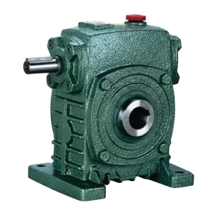
The EP-WPKS is a hollow-bore output single speed reducer with a solid input shaft, covering unit weights from 4 kg at the smallest frame through to 365 kg at the largest. Its hollow-bore output configuration is directly suited to final drive test stand applications where the test stand coupling shaft passes through the reducer output hub — a layout that reduces the overhang load on the reducer output bearing compared to a projecting solid shaft with a bolted coupling. This is particularly relevant for large excavator final drive test stands in facilities in Australia, South Korea, and Germany where the coupling element between the reducer and the final drive input must handle shock torques during load-step transitions in the test protocol.
The WPKS series spans the frame sizes needed for test stands covering mid-size to heavy-duty crawlers, with worm gear reduction ratios from 1/5 through 1/60 available across the range. The hollow-bore keyway dimensions in the WPKS output hub accommodate the shaft-diameter range of most OEM test coupling designs without custom modification.
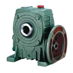
The EP-WPDKA combines a motor-flange input with a hollow-bore output — making it a dual-interface single speed reducer that eliminates both input coupling hardware and output shaft overhang simultaneously. For final drive test stands where the VFD-controlled test motor attaches directly to the reducer input flange and the test stand coupling shaft passes through the hollow output bore, the WPDKA configuration produces the most compact and structurally clean drive assembly of any WP series variant. The unit weight range of 5 to 350 kg spans from compact test stands for mini excavators through to heavy-duty rigs used for 50-tonne class crawler excavator final drive verification.
OEM test equipment integrators in Japan and the USA increasingly specify the WPDKA because it reduces test stand assembly time: the motor bolts directly to the reducer input face using standard IEC B5 flange dimensions, and the test coupling shaft slides into the output bore from the driven side — two interfaces established without separate coupling alignment procedures. This cuts stand changeover time when switching between different final drive models on a shared test rig.
Test Protocol Considerations That Affect Reducer Specification
The single speed reducer in a final drive test stand must function reliably across the full range of operating points defined by the test protocol — not just the nominal rated condition. Test protocols for crawler undercarriage final drives in OEM facilities typically include a break-in run at reduced load and speed, followed by a series of stepped load increases at constant speed, a temperature soak at rated load to confirm thermal stability of the final drive under test, a noise measurement at defined speed and load points, and a leak check after the thermal soak sequence. Each of these phases imposes different requirements on the drive-side single speed reducer.
During the break-in phase, the reducer must follow the test motor’s slow speed ramp without cogging — a worm gear’s sliding contact characteristic produces smooth output even at very low input speeds, which is an advantage over helical or spur gear reducers that can exhibit torque ripple during low-speed ramp-up with VFD control. During the noise measurement phase, the reducer’s own noise contribution must be below the threshold that would mask the final drive noise signature — WP series worm reducers, with their sliding mesh contact and absence of gear tooth impact loading, produce a lower structure-borne noise level than spur or helical alternatives of equivalent ratio, making them preferable on test stands where noise measurement is a primary pass-fail criterion.
The worm gear sliding contact provides smooth torque transfer at low speed, supporting accurate VFD-controlled slow ramps without velocity discontinuities that would disturb early-stage data logging on the final drive being evaluated.
Stepped torque increases at the test stand output create brief impulse loads on the single speed reducer. Service factor 1.5–2.0 must absorb these impulses without triggering worm wheel tooth fatigue. At low worm gear reduction ratios (1/5 to 1/10) used for high-speed final drive test inputs, the higher mesh efficiency reduces internal heat build-up during extended load-step sequences.
Extended operation at rated load elevates reducer housing temperature. The thermal mass of the cast iron housing moderates peak temperature rise during soak sequences. For test stands measuring final drive oil temperature as a test criterion, the reducer’s own thermal output must be accounted for when positioning the temperature sensors — the reducer and final drive should be thermally decoupled where possible by the test stand’s coupling arrangement.
The worm gear sliding contact mesh produces lower airborne noise than spur or helical stages at equivalent ratios and loads. This is the primary acoustic reason for specifying a worm speed reducer rather than an alternative drive type in test stand applications where final drive noise signature is a formal pass-fail criterion in the OEM’s quality procedure.

Installation Requirements and Maintenance Scheduling
Installing a worm gear single speed reducer in a final drive test stand follows the same mechanical principles as in production machine applications, but with additional attention to alignment accuracy and vibration isolation. The test stand frame must be welded or bolted steel fabrication of sufficient stiffness that deflection under peak test torque does not shift the reducer position relative to the final drive fixture — any positional shift translates into coupling misalignment that introduces shaft bending load into the reducer output bearing and produces a spurious torque signal in the test measurement channel.
Shaft alignment between the reducer output and the final drive input coupling should be verified with a dial indicator before each production run, particularly after the test stand is relocated or after any structural work on the test cell. For motor-flange input configurations (WPDKA), verify the motor register fit within IEC B5 pilot circle tolerances before tightening the flange mounting bolts — a loose pilot fit introduces radial play that produces cyclic misalignment at motor operating speed.
Oil change scheduling for test stand reducers in high-utilisation OEM facilities in Germany, Japan, South Korea, and Australia should be based on operating hours rather than calendar time. The first change at 200–300 hours removes metal particles from the worm wheel bedding-in process. Subsequent changes at 2,000 hours with mineral ISO VG 220 oil, or 4,000–5,000 hours with synthetic PAO ISO VG 220, keep the mesh lubricated through extended production runs without requiring stand downtime at inconvenient points in the test schedule. Oil samples taken at each change should be analysed for metal content — rising bronze particle concentration in the gear oil is an early indicator of worm wheel tooth wear that can be addressed by ratio re-evaluation or service factor correction before a failure occurs on the stand.
Compatible Products for Complete Test Stand Drive Systems
A final drive test stand drive system requires reliable compatibility between the test motor, the single speed reducer, and the coupling to the unit under test. The following product categories support complete drive system procurement from a single source, simplifying OEM test equipment integration.
Beyond the WP-series single speed reducer family, the full worm gearbox range covers double-stage configurations (ratios to 1/900) for test stands serving very-low-speed final drive applications such as large mining dozers and crawler cranes. Universal-type WPW series units provide multi-orientation input/output flexibility for test stand designs that must accommodate multiple machine classes with a single gearbox position. Sourcing the complete range from one manufacturing facility ensures dimensional interchangeability and shared spare parts across a test department’s full gearbox inventory.

Test stand primary motors paired with a single speed reducer must have VFD-compatible winding insulation and the correct IEC flange format to bolt directly to motor-flange reducer variants (WPDKA series). Our electric motor range covers IEC B5 and B14 flange configurations from 0.12 kW to 15 kW, with inverter-duty insulation class F winding standard across all frame sizes.

À propos de notre usine de fabrication
Our production facility specialises in industrial power transmission components — worm gear reducers, agricultural gearboxes, planetary drives, power take-off shafts, hydraulic cylinders, gears, chains, and electric motors — all manufactured under an ISO 9001:2015 certified quality management system. Our engineering and production teams have over 20 years of experience designing gearboxes and mechanical assemblies in ductile iron, cast iron, cast steel, precision cast steel, and cast aluminium to meet OEM and standard dimensional requirements across DIN, ISO, ANSI, JIS, and AGMA specifications.
All gear cutting, heat treatment, CNC worm thread grinding, assembly, and outgoing dimensional inspection are carried out in-house, providing full material traceability from raw casting to finished worm gear speed reducer. Our customers include heavy equipment OEM facilities, test equipment integrators, industrial plant engineers, and aftermarket replacement programs across North America, Europe (Germany, Italy, Poland), South America (Brazil, Colombia), the Middle East, Southeast Asia, Australia, and South Africa.
Foire aux questions
Q1. What single speed reducer ratio is correct for a final drive test stand in a Korean excavator manufacturing plant where the final drive input must run at 300 RPM from a 1450 RPM test motor?
For a 1450 RPM test motor driving a final drive input at 300 RPM, the required single speed reduction ratio is 1450 / 300 = approximately 1/4.8 — in practice, the nearest standard ratio is 1/5. This places the selection at the low end of the worm gear single speed reducer range, where mesh efficiency is highest (typically 85–90% at 1/5 ratio), which is beneficial in a test stand application because it minimises heat generation in the reducer drive train and avoids thermal contamination of the final drive temperature measurement. At the WP series 1/5 ratio with a 1450 RPM input, confirm the worm shaft speed rating for the selected frame size — high input speeds on small-frame worm reducers can exceed the rated worm shaft peripheral speed and accelerate worm wheel wear.
Q2. How does a worm gear single speed reducer contribute to lower noise readings during final drive noise testing at a German OEM heavy equipment assembly facility?
The worm gear mesh operates through sliding contact between the worm thread and wheel tooth rather than the rolling impact contact of helical or spur gear pairs. This sliding interface produces a lower impulse loading pattern per revolution, which means the structure-borne noise transmitted through the test stand frame from the drive-side single speed reducer is lower in amplitude than an equivalent helical or spur gear drive at the same ratio. In German OEM noise measurement protocols — which typically use a microphone array around the final drive housing and measure airborne noise at defined test points — the lower drive-side noise floor from a worm gear reducer gives the measurement system a wider margin to detect genuine final drive defects such as planet gear tooth damage or bearing defects, rather than masking these with drive train noise. Specifying a worm speed reducer over a helical alternative in the test stand therefore directly improves the measurement sensitivity and reduces false-pass rates.
Q3. Which single speed reducer configuration — solid shaft output or hollow bore — is better suited for connecting to the input shaft of a bulldozer final drive on a test stand in an Australian mining equipment facility?
For connecting to the input shaft of a bulldozer final drive on a test stand in an Australian mining equipment facility, the hollow-bore output configuration is the more practical choice in most stand designs. The final drive input shaft passes directly through the reducer output hub and is secured by a key and clamping arrangement, eliminating the need for a separate coupling element and its associated angular and parallel alignment requirements. This is particularly relevant in Australian mining equipment facilities where the final drive units being tested are large — input shaft diameters on 50-tonne class bulldozer final drives can reach 60–80 mm — and where the test stand fixture must be reconfigured rapidly between machine models. The hollow-bore WPKS or WPDKA series reducers accommodate different shaft diameters by changing the bore insert or coupling bush rather than replacing the entire gearbox, reducing changeover time on a shared test stand.
Q4. When should I apply a service factor of 2.0 to the torque calculation for a single speed reducer in a heavy equipment final drive test stand running stepped load protocols in Japan?
A service factor of 2.0 is appropriate for a final drive test stand reducer when the test protocol includes abrupt load steps — particularly when the torque application goes from zero to full rated load in under two seconds, which is common in step-load efficiency tests in Japanese OEM protocols. The instantaneous torque during a rapid load step can reach 2.0–2.5 times the steady-state value, depending on the drive train’s rotational inertia and the response time of the load control system. Applying a service factor of 2.0 ensures that the worm wheel’s tooth surface contact stress during the step event stays within the material’s fatigue limit. If the load steps are more gradual — ramp time greater than 5 seconds — a service factor of 1.5 is typically sufficient. Always base the calculation on the actual measured load step profile from the test stand controller rather than the nominal rated torque of the final drive unit under test, as some test protocols apply overload torques above the final drive’s design working load to verify margin.
Q5. Where can test equipment integrators in Germany find a customized single speed reducer manufacturer who can supply worm gear drives with non-standard ratios for multi-model final drive test stands?
Test equipment integrators in Germany and across the EU who need single speed reducers with non-standard ratios — for test stands that must cover multiple final drive input speeds across machine model families — should engage directly with manufacturing facilities that perform worm thread grinding in-house and can demonstrate the gear-cutting capability to produce non-standard tooth counts and module sizes outside the standard catalogue ratio steps. Key capabilities to evaluate: can the manufacturer produce the ratio you need between standard 1/5 and 1/60 steps? Can they supply 3D STEP files for the specific ratio unit to verify coupling clearances in the test stand model? Is ISO 9001:2015 quality documentation provided with each shipment to satisfy incoming inspection requirements at German OEM facilities? Direct factory engagement with a vertically integrated manufacturer — one who controls casting, machining, heat treatment, grinding, and assembly internally — provides the most reliable path to consistent quality and on-time delivery for test stand procurement programs where delivery delays halt final drive production lines.
Éditeur : PXY