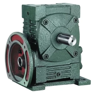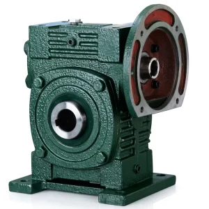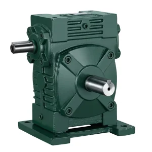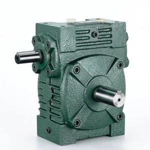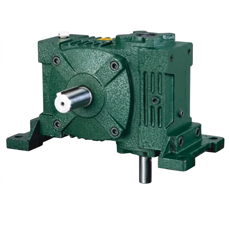
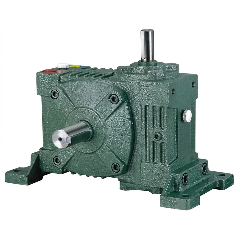
EP-WPWV-T ตัวลดความเร็วอเนกประสงค์
EP-WPWV-T เป็นเกียร์ทดรอบอเนกประสงค์ที่ทำจากเหล็กหล่อ สร้างขึ้นบนตัวเรือนสองแบบที่เสริมกันภายในตระกูลขนาด WPW เดียวกัน ได้แก่ WPWV ซึ่งให้เพลาส่งออกแนวตั้งจากอินพุตแนวนอน และ WPWT ซึ่งมีเพลาส่งออกติดตั้งด้านบนพร้อมรูส่งออกที่หันขึ้นด้านบน ทำให้เป็นตัวเลือกที่เหมาะสมเมื่อรูปทรงการติดตั้งต้องการการส่งออกในทิศทางที่เกียร์ทดรอบแนวนอนมาตรฐานไม่สามารถรองรับได้ ทั้งสองแบบมีขนาดเฟรม 11 ขนาดเดียวกัน (40 ถึง 250) อัตราส่วนลดรอบเดียวกันตั้งแต่ 1/5 ถึง 1/60 และขนาดอินเทอร์เฟซเพลาเดียวกัน ซึ่งช่วยลดความซับซ้อนในการออกแบบเครื่องจักรอย่างมากเมื่อจำเป็นต้องเปลี่ยนทิศทางการส่งออกระหว่างรุ่นผลิตภัณฑ์หรือข้อกำหนดเฉพาะภูมิภาค
ชุดลดความเร็วแบบเฟืองตัวหนอนนี้ มีน้ำหนักตั้งแต่ 5 กก. สำหรับขนาด 40 จนถึง 374 กก. สำหรับขนาด 250 ครอบคลุมการใช้งานตั้งแต่ไดรฟ์เครื่องมือขนาดเล็กและระบบลำเลียงเบา ไปจนถึงถังผสมขนาดใหญ่ โต๊ะหมุน และระบบกวนแบบแกนตั้ง ช่วงขนาดที่หลากหลายภายในตระกูลตัวเรือนเดียวกัน หมายความว่าวิศวกรที่กำหนดผลิตภัณฑ์นี้สำหรับการออกแบบเครื่องจักรใหม่ สามารถเลือกคลาสแรงบิดที่ต้องการได้อย่างแม่นยำโดยไม่ต้องซื้อเกินความจำเป็น ซึ่งเป็นปัจจัยสำคัญทั้งต่อต้นทุนอุปกรณ์และพื้นที่ติดตั้งที่มีอยู่ โดยเฉพาะอย่างยิ่งในการติดตั้งแบบกะทัดรัดหรือที่มีความสูงจำกัด
EP-WPWV-T ตัวลดความเร็วอเนกประสงค์
ชุดลดความเร็วแบบเฟืองตัวหนอน WPWV และ WPWT — ขนาด 40–250 | อัตราทด 1/5–1/60 | รับน้ำหนักได้สูงสุด 374 กก. | แบบติดตั้งแนวตั้งและแบบส่งกำลังออกด้านบน
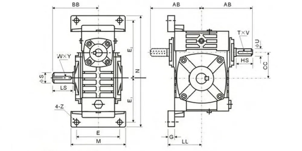
ข้อมูลจำเพาะทางเทคนิคของตัวลดความเร็วอเนกประสงค์ EP-WPWV-T
ขนาดทั้งหมดระบุเป็นมิลลิเมตร เว้นแต่จะระบุไว้เป็นอย่างอื่น ใช้แถบเลื่อนแนวนอนบนหน้าจอขนาดเล็กเพื่อดูคอลัมน์ทั้งหมด
| ขนาด | อัตราส่วน | เอบี | BB | ซีซี | แอลแอล | เอ็ม | เอ็น | อี | อี₁ | อี₂ | จี | ซ | เอชเอส | ยู | ที×วี | แอลเอส | เอส | น้ำหนัก (กก.) |
|---|---|---|---|---|---|---|---|---|---|---|---|---|---|---|---|---|---|---|
| 40 | 1/5 | 87 | 74 | 40 | 63 | 90 | 187 | 70 | 72 | 97 | 12 | 10 | 25 | 12 | 4×2.5 | 28 | 14 | 5 |
| 50 | 1/10 | 108 | 97 | 50 | 70 | 120 | 226 | 95 | 90 | 110 | 14 | 12 | 30 | 12 | 4×2.5 | 40 | 17 | 8 |
| 60 | 1/15 | 120 | 112 | 60 | 80 | 130 | 257 | 105 | 102 | 129 | 15 | 12 | 40 | 15 | 5×3 | 50 | 22 | 11 |
| 70 | 1/20 | 140 | 131 | 70 | 95 | 150 | 305 | 115 | 120 | 155 | 20 | 15 | 40 | 18 | 5×3 | 60 | 28 | 15.5 |
| 80 | 1/25 | 160 | 142 | 80 | 105 | 170 | 350 | 135 | 140 | 180 | 20 | 15 | 50 | 22 | 7×4 | 65 | 32 | 24 |
| 100 | 1/30 | 190 | 169 | 100 | 135 | 190 | 410 | 155 | 165 | 215 | 22 | 15 | 50 | 25 | 7×4 | 75 | 38 | 38 |
| 120 | 1/40 | 219 | 190 | 120 | 160 | 230 | 494 | 180 | 195 | 255 | 25 | 18 | 65 | 30 | 7×4 | 85 | 45 | 56 |
| 135 | 1/50 | 249 | 210 | 135 | 185 | 250 | 559 | 200 | 230 | 285 | 30 | 18 | 75 | 35 | 10×4.5 | 95 | 55 | 84 |
| 155 | 1/60 | 295 | 252 | 155 | 220 | 275 | 605 | 220 | 250 | 305 | 35 | 21 | 85 | 40 | 12×5 | 110 | 60 | 129 |
| 175 | 1/60 | 314 | 255 | 175 | 240 | 310 | 675 | 250 | 273 | 348 | 40 | 21 | 85 | 45 | 14×5.5 | 110 | 65 | 157 |
| 200 | 1/60 | 342 | 319 | 200 | 280 | 360 | 749 | 290 | 305 | 390 | 40 | 24 | 95 | 50 | 14×5.5 | 125 | 70 | 224 |
| 250 | 1/60 | 420 | 385 | 250 | 315 | 460 | 920 | 380 | 375 | 475 | 45 | 28 | 110 | 60 | 18×7 | 155 | 90 | 374 |
ข้อดีสำคัญ 5 ประการของตัวลดความเร็วอเนกประสงค์ EP-WPWV-T
① รูปทรงแนวตั้งและช่องระบายอากาศด้านบนในตระกูลเดียวกัน
ตัวเรือนสองแบบ — WPWV และ WPWT ตัวลดความเร็วอเนกประสงค์ — ให้ตัวเลือกการส่งออกทั้งแบบแนวตั้งและแบบเพลาบนจากแม่แบบขนาดเดียวกัน ผู้ผลิตเครื่องจักรสามารถเปลี่ยนทิศทางการส่งออกระหว่างรุ่นเครื่องจักรต่างๆ ได้โดยไม่ต้องจัดหาจากซัพพลายเออร์ใหม่หรือตรวจสอบขนาดอินเทอร์เฟซเพลาอีกครั้ง ความสม่ำเสมอนี้ช่วยลดความซับซ้อนในการจัดซื้อสำหรับผู้ผลิตอุปกรณ์ดั้งเดิม (OEM) ที่ผลิตเครื่องจักรหลายรุ่นสำหรับตลาดต่างๆ
② ตัวเลือกทิศทางเพลาแบบขยาย
ตัวลดความเร็วอเนกประสงค์ WPWT รองรับการกำหนดค่าทิศทางเพลาที่แตกต่างกันห้าแบบ (A–E) รวมถึงการจัดเรียงแบบเอาต์พุตคู่ ซึ่งมีความยืดหยุ่นในการจัดวางมากกว่าเกียร์ทดรอบแบบหนอนสำหรับงานหนักที่มีขนาดเทียบเท่ากันส่วนใหญ่ที่วางจำหน่ายทั่วไป สำหรับวิศวกรโรงงานในเยอรมนี เกาหลีใต้ และบราซิล ที่ต้องเผชิญกับข้อกำหนดทางเรขาคณิตของระบบขับเคลื่อนที่ไม่เป็นมาตรฐานอยู่เป็นประจำ ความหลากหลายของผลิตภัณฑ์ในแคตตาล็อกนี้จะช่วยลดความจำเป็นในการผลิตอะแดปเตอร์แบบกำหนดเอง
③ ความสามารถในการเบรกอัตโนมัติอัตราทดสูง
ที่อัตราส่วนลด 1/40 ขึ้นไป มุมนำที่ตื้นของเกลียวตัวหนอนจะสร้างแรงเสียดทานเพียงพอที่จะป้องกันการหมุนย้อนกลับภายใต้สภาวะรับน้ำหนักคงที่ส่วนใหญ่ สำหรับไดรฟ์แกนแนวตั้ง ซึ่งเป็นแอปพลิเคชันหลักของรุ่น WPWV และ WPWT คุณลักษณะนี้ช่วยลดความจำเป็นในการใช้เบรกยึดเชิงกลหรือไฟฟ้าแยกต่างหากในงานติดตั้งที่ต้องยึดน้ำหนักจำนวนมาก ซึ่งจะช่วยลดต้นทุนของระบบและจำนวนชิ้นส่วน
④ ขนาดส่วนต่อประสานเพลาที่สม่ำเสมอในทุกขนาด
ขนาดเส้นผ่านศูนย์กลางของเพลาขาเข้าและขาออก ขนาดร่องลิ่ม (T×V) และรูปแบบการติดตั้งสลักเกลียว เป็นไปตามรูปแบบการปรับขนาดที่คาดการณ์ได้ตลอดช่วงขนาด 40–250 เมื่อแอปพลิเคชันต้องการแรงบิดที่มากกว่าที่ระบุไว้ในตอนแรก ซึ่งเป็นผลลัพธ์ทั่วไปเมื่อภาระของกระบวนการเพิ่มขึ้นเมื่อเวลาผ่านไป การเพิ่มขนาดเฟรมให้ใหญ่ขึ้นจะต้องการเพียงการเปลี่ยนแปลงที่ตัวยึดมอเตอร์และข้อต่อเท่านั้น ไม่จำเป็นต้องออกแบบระบบขับเคลื่อนใหม่ทั้งหมด
⑤ ช่วงแรงบิดกว้าง — 5 กก. ถึง 374 กก.
ชุดเกียร์ทดรอบแบบหนอนขนาด 250 น้ำหนัก 374 กก. เป็นหนึ่งในชุดเกียร์ทดรอบมาตรฐานขนาดใหญ่ที่สุดที่มีจำหน่าย เหมาะสำหรับงานผสมในอุตสาหกรรมหนักและการลำเลียงขนาดใหญ่ ซึ่งหากไม่มีชุดเกียร์ทดรอบขนาดนี้จะต้องใช้เกียร์แบบสั่งทำพิเศษ การที่มีขนาดความจุนี้ในผลิตภัณฑ์มาตรฐานที่อยู่ในแคตตาล็อก หมายถึงระยะเวลารอคอยที่สั้นลง ขนาดชิ้นส่วนอะไหล่ที่ระบุไว้ และเส้นทางการจัดหาอะไหล่ที่ทราบแน่ชัด ซึ่งเป็นข้อดีที่สำคัญอย่างยิ่งต่อการดำเนินงานในอุตสาหกรรมตลอด 24 ชั่วโมง 7 วันต่อสัปดาห์ในเอเชียตะวันออกเฉียงใต้ ตะวันออกกลาง และออสเตรเลีย
หลักการทำงาน — วิธีการทำงานของเกียร์ทดรอบแบบเฟืองตัวหนอน WPWV และ WPWT
แก่นแท้ของทุกสิ่ง ตัวลดความเร็วอเนกประสงค์ ในสายการผลิต WPW นั้นประกอบด้วยเฟืองตัวหนอนสองตัว เพลาตัวหนอนที่แข็งแรงทนทาน – หมุนด้วยความเร็วรอบมอเตอร์ – มีเกลียวแบบเฮลิคอลที่เข้ากับโปรไฟล์ฟันโค้งของล้อตัวหนอนอย่างแม่นยำที่มุม 90 องศา การหมุนครบหนึ่งรอบของเพลาตัวหนอนจะทำให้ล้อเคลื่อนที่ไปข้างหน้าหนึ่งระยะฟันพอดี ดังนั้นความเร็วรอบเอาต์พุตจึงลดลงด้วยปัจจัยที่เท่ากับจำนวนฟันของล้อหารด้วยจำนวนการเริ่มต้นของเกลียวบนตัวหนอน นี่คือหลักการทางกลศาสตร์พื้นฐานในการเลือกอัตราส่วนลดของเฟืองตัวหนอน: ล้อ 60 ฟันที่มีตัวหนอนเริ่มต้นเดียวจะให้การลด 1/60; การเพิ่ม 10 ฟันจะให้การลด 1/10
ในรุ่น WPWV เพลาส่งกำลังของเฟืองตัวหนอนจะออกมาตั้งฉากกับฐานยึด โดยชี้ลงด้านล่างหรือไปด้านข้าง ขึ้นอยู่กับทิศทางการติดตั้ง รูปทรงเรขาคณิตนี้มีประโยชน์เมื่อชิ้นส่วนที่ถูกขับเคลื่อน (ใบพัดผสม โต๊ะหมุน ลูกกลิ้งสายพานลำเลียง) อยู่ต่ำกว่าเกียร์ในโครงสร้างเครื่องจักร ในรุ่น WPWT เพลาส่งกำลังจะยื่นขึ้นไปด้านบนผ่านส่วนบนของตัวเรือน ซึ่งเหมาะสำหรับงานที่แหล่งขับเคลื่อนอยู่ต่ำกว่าภาชนะบรรจุหรือโครงสร้างสายพานลำเลียง และเพลาส่งกำลังจำเป็นต้องยื่นขึ้นไปถึงชิ้นส่วนที่ถูกขับเคลื่อน ทั้งสองแบบยังคงใช้หลักการทางฟิสิกส์ของเฟืองตัวหนอนเหมือนกัน กล่าวคือ แรงบิดเอาต์พุตเท่ากับแรงบิดอินพุตคูณด้วยอัตราส่วนลดของเฟืองตัวหนอน ลดลงด้วยประสิทธิภาพเชิงกลของการเข้าคู่กันของเฟืองตัวหนอนที่อัตราส่วนลดนั้น
ประสิทธิภาพจะลดลงเมื่ออัตราส่วนลดเพิ่มขึ้น ซึ่งเป็นลักษณะพื้นฐานของระบบขับเคลื่อนเฟืองตัวหนอนที่แตกต่างจากระบบขับเคลื่อนแบบเกลียวหรือแบบดาวเคราะห์ โดยทั่วไปแล้ว ที่อัตราส่วนลด 1/5 ชุดเกียร์เฟืองตัวหนอนคุณภาพดีจะให้ประสิทธิภาพ 85–92% ที่อัตราส่วนลด 1/60 ประสิทธิภาพจะลดลงเหลือ 40–60% และชุดเกียร์มักจะล็อคตัวเองเมื่อหมุนย้อนกลับ สำหรับการใช้งานในช่วง WPWV และ WPWT เช่น การผสมแกนแนวตั้ง การจัดตำแหน่ง และการกำหนดตำแหน่งความเร็วต่ำ การแลกเปลี่ยนประสิทธิภาพนี้มักเป็นที่ยอมรับได้ เนื่องจากภาระเกิดขึ้นอย่างต่อเนื่องและพฤติกรรมการเบรกด้วยตนเองช่วยลดความจำเป็นในการใช้อุปกรณ์เบรกเสริม วิศวกรที่ประเมินสิ่งนี้ในฐานะตัวลดความเร็วเฟืองตัวหนอนอเนกประสงค์ขนาดใหญ่สำหรับระบบขับเคลื่อนสายพานลำเลียงต่อเนื่องที่ใช้งานหนัก ควรพิจารณาความจุความร้อนอย่างรอบคอบสำหรับอัตราส่วนลดที่สูงกว่า 1/30

มาตรฐานวัสดุและวิศวกรรมของตัวลดความเร็วแบบสากล
ตัวเรือนของเกียร์ทดรอบอเนกประสงค์ EP-WPWV-T ผลิตจากเหล็กหล่อสีเทาเกรด GB/T 9439 HT200 ซึ่งเป็นวัสดุที่ได้รับการคัดเลือกเนื่องจากมีความแข็งแรงในการรับแรงอัดสูง ความสามารถในการลดแรงสั่นสะเทือน และความสามารถในการขึ้นรูป ซึ่งทั้งหมดนี้มีความสำคัญต่อตัวเรือนเกียร์ที่ต้องรักษาการจัดแนวของรูแบริ่งภายใต้ภาระคงที่ตลอดการใช้งานต่อเนื่องหลายปี ลวดลายครีบภายนอกที่พบได้ทั่วไปในตัวเรือนเกียร์ทดรอบอเนกประสงค์ WPW ไม่ได้มีไว้เพื่อความสวยงามเท่านั้น แต่ครีบเหล่านี้ช่วยเพิ่มพื้นที่ผิวภายนอกประมาณ 30–40 ตัน เมื่อเทียบกับกล่องที่มีผนังเรียบ ช่วยเพิ่มประสิทธิภาพการระบายความร้อนแบบพาความร้อนโดยตรงในระหว่างรอบการทำงานต่อเนื่องในสภาพแวดล้อมที่ไม่มีการติดตั้งระบบระบายความร้อนแบบบังคับ
เพลาตัวหนอนผลิตจากเหล็กอัลลอย 20CrMnTi ผ่านกระบวนการคาร์บูไรซิ่งจนมีความหนาของชั้นผิว 0.8–1.2 มม. และชุบแข็งผิวจนมีความแข็ง 58–62 HRC ความแข็งระดับนี้ เมื่อรวมกับความเค้นตกค้างจากการอัดตัวที่เกิดจากกระบวนการคาร์บูไรซิ่ง จะช่วยต้านทานกลไกการสึกหรอแบบยึดติดและแบบขัดถู ซึ่งเป็นกลไกหลักที่เกิดขึ้นบนพื้นผิวสัมผัสของตัวหนอน โดยที่ความเร็วในการเลื่อนระหว่างตัวหนอนและล้อจะสูงกว่าการสัมผัสของเฟืองตรงหรือเฟืองเกลียวในระดับเดียวกันอย่างมาก ล้อตัวหนอนหล่อขึ้นจากบรอนซ์ฟอสฟอรัส ZCuSn10Pb1 บนดุมเหล็กหล่อเหนียว บรอนซ์ให้ความยืดหยุ่นและค่าสัมประสิทธิ์แรงเสียดทานต่ำที่จำเป็นต่อการปกป้องด้านข้างของตัวหนอนที่ผ่านการชุบแข็งในช่วงเริ่มต้นการใช้งานและตลอดอายุการใช้งาน ในขณะที่ดุมเหล็กหล่อเหนียวสามารถรับแรงบิดได้โดยไม่เสี่ยงต่อการแตกหักแบบเปราะ
ตัวอย่างการใช้งาน — อุปกรณ์ลดความเร็วอเนกประสงค์ WPWV และ WPWT เหมาะสำหรับใช้งานในสถานการณ์ใดบ้าง
โต๊ะหมุนดัชนี — เยอรมนีและญี่ปุ่น
โต๊ะหมุนกำหนดตำแหน่งความแม่นยำสูงที่ใช้ในเครื่องจักร CNC และสายการประกอบอัตโนมัติทั่วประเทศเยอรมนีและญี่ปุ่น ต้องการตัวลดเกียร์หนอนอัตราทดสูงที่มีระยะคลอนน้อยที่สุดและสามารถยึดจับได้อย่างมั่นคงเมื่อหยุดนิ่ง การกำหนดค่าเอาต์พุตด้านบนของ WPWT เหมาะสมกับงานนี้เป็นอย่างดี: เพลาส่งออกยื่นขึ้นไปที่ดุมโต๊ะโดยตรง อัตราทด 1/40–1/60 ให้แรงเสียดทานในการยึดจับที่จำเป็น และขนาดเพลาอินพุตที่สม่ำเสมอในขนาดเฟรมตัวลดความเร็วอเนกประสงค์ของ WPW ทำให้สามารถใช้หน้าแปลนมอเตอร์เดียวกันกับขนาดเส้นผ่านศูนย์กลางโต๊ะที่หลากหลายได้
ระบบขับเคลื่อนเครื่องผสมสารเคมีและเภสัชกรรม — สหรัฐอเมริกาและเกาหลีใต้
โดยทั่วไปแล้ว ระบบขับเคลื่อนของเครื่องปฏิกรณ์แบบกวนและถังผสมในโรงงานเคมีทั่วสหรัฐอเมริกาและเกาหลีใต้ จะติดตั้งมอเตอร์และเกียร์ไว้เหนือถัง โดยมีเพลาส่งกำลังยื่นลงมาผ่านหน้าแปลนเข้าไปในของเหลวในกระบวนการ ตัวลดความเร็วอเนกประสงค์ WPWV แบบส่งกำลังแนวตั้งเป็นแบบมาตรฐานสำหรับโครงสร้างนี้ ที่ขนาด 175–250 และอัตราส่วน 1/60 ตัวลดความเร็วอเนกประสงค์ EP-WPWV-T ให้ความเร็วรอบต่ำและแรงบิดสูงที่จำเป็นสำหรับการผสมของเหลวที่มีความหนืดสูงโดยไม่ต้องใช้เกียร์ขั้นกลาง และฟังก์ชันเบรกในตัวจะป้องกันไม่ให้ใบพัดหมุนอย่างอิสระเมื่อตัดไฟ
สายพานลำเลียงเหนือศีรษะและระบบขับเคลื่อนรถเข็น — ออสเตรเลียและเอเชียตะวันออกเฉียงใต้
ระบบสายพานลำเลียงเหนือศีรษะที่ใช้ในโรงงานพ่นสีรถยนต์ โรงงานแปรรูปอาหาร และโรงงานผลิตเสื้อผ้าในออสเตรเลีย มาเลเซีย และไทย ใช้เกียร์ทดรอบแบบหนอน (worm drive reducers) ในชุดขับเคลื่อนรถเข็น เพลาส่งกำลังด้านบนของ WPWT เข้าสู่ดุมล้อรถเข็นจากด้านล่าง ซึ่งเป็นรูปทรงที่ช่วยลดความจำเป็นในการใช้ข้อต่อมุมฉากหรือเฟืองดอกจอกขั้นกลาง ด้วยขนาด 60–100 และอัตราส่วน 1/20–1/30 เกียร์ทดรอบอเนกประสงค์ EP-WPWV-T ให้ความเร็วต่ำที่ควบคุมได้และแรงบิดคงที่ ซึ่งเป็นสิ่งที่ระบบขับเคลื่อนสายพานลำเลียงเหนือศีรษะต้องการสำหรับการขนส่งสินค้าอย่างราบรื่นโดยปราศจากการสั่นสะเทือนหรือความผันผวนของความเร็ว
อุปกรณ์ขับเคลื่อนประตูและวาล์ว — ตะวันออกกลางและบราซิล
โครงการบำบัดน้ำ โครงสร้างพื้นฐานการชลประทาน และท่อส่งกระบวนการทางอุตสาหกรรมทั่วตะวันออกกลางและบราซิล จำเป็นต้องใช้แอคชูเอเตอร์ที่มีกำลังสูงและทำงานช้าสำหรับประตูน้ำ วาล์วบอลขนาดใหญ่ และวาล์วผีเสื้อ ตัวลดความเร็วอเนกประสงค์ EP-WPWV-T ขนาด 120–200 เมื่อรวมกับมอเตอร์ลดเกียร์แบบหนอน จะให้คุณสมบัติที่รวมกันของอัตราทดเกียร์สูง การล็อคตัวเองเมื่อหยุดนิ่ง และเพลาส่งออกที่ติดตั้งในแนวตั้งหรือด้านบนซึ่งเชื่อมต่อโดยตรงกับอินเทอร์เฟซก้านวาล์วมาตรฐาน ทั้งหมดนี้โดยไม่ต้องใช้ระบบไฮดรอลิกที่ซับซ้อนซึ่งแอคชูเอเตอร์แบบใช้พลังงานไฟฟ้าต้องการ
ประสบการณ์กว่าสิบปีในการผลิตเกียร์ทดรอบแบบหนอน
โรงงานของเราผลิตอุปกรณ์ส่งกำลังเชิงกลมานานกว่าทศวรรษ โดยมีผลิตภัณฑ์หลากหลาย ตั้งแต่เกียร์บ็อกซ์สำหรับงานเกษตรกรรม เกียร์ทดรอบแบบหนอน เกียร์ทดรอบแบบดาวเคราะห์ เพลาส่งกำลัง กระบอกไฮดรอลิก เกียร์ เฟืองโซ่ และมอเตอร์ โรงงานดำเนินงานภายใต้มาตรฐาน ISO 9001:2015 โดยมีขั้นตอนการควบคุมคุณภาพที่บันทึกไว้ ครอบคลุมการตรวจสอบวัสดุขาเข้า การตรวจสอบขนาดระหว่างกระบวนการ และการทดสอบประสิทธิภาพขั้นสุดท้ายของเกียร์บ็อกซ์ทุกชิ้นก่อนจัดส่ง
การออกแบบและการผลิตครอบคลุมวัสดุที่หลากหลาย: เหล็กดัด เหล็กหล่อ เหล็กหล่อ เหล็กหล่อความแม่นยำสูง และตัวเรือนอะลูมิเนียมหล่อ ล้วนผลิตขึ้นเองภายในบริษัท รวมถึงเฟือง เฟืองโซ่ เฟืองตัวหนอน รอก เพลาตัวหนอน และชิ้นส่วนทางกลมาตรฐานและไม่มาตรฐาน การบูรณาการในแนวดิ่งนี้ทำให้เราควบคุมคุณภาพการหล่อ ความคลาดเคลื่อนในการกลึง และพารามิเตอร์การอบชุบความร้อนได้อย่างโดยตรง ซึ่งเป็นตัวแปรที่กำหนดความน่าเชื่อถือในระยะยาวของชุดเกียร์ตัวหนอนในการใช้งานต่อเนื่องในอุตสาหกรรม
เวิร์คช็อป




ผลิตภัณฑ์ที่เข้ากันได้กับระบบ — ชุดไดรฟ์ครบชุดจากผู้จำหน่ายรายเดียว
ตัวลดความเร็วอเนกประสงค์ EP-WPWV-T ใช้มาตรฐานอินเทอร์เฟซมอเตอร์ IEC และขนาดเพลามาตรฐานอุตสาหกรรมตลอดทั้งระบบ ทำให้ง่ายต่อการสร้างระบบขับเคลื่อนที่สมบูรณ์จากผลิตภัณฑ์ที่เข้ากันได้โดยไม่ต้องดัดแปลงแก้ไข
การนำตัวลดความเร็วอเนกประสงค์ EP-WPWV-T มาประกอบเข้ากับมอเตอร์ไฟฟ้าที่เหมาะสม จะทำให้ได้ตัวลดความเร็วแบบเฟืองตัวหนอนที่ขับเคลื่อนด้วยมอเตอร์ ซึ่งได้รับการจัดตำแหน่งไว้ล่วงหน้าและพร้อมติดตั้ง มอเตอร์ไฟฟ้าของเรามีให้เลือกทั้งแบบเฟสเดียวและสามเฟส ขนาด 0.18–22 กิโลวัตต์ เฟรม IEC B3/B5/B14 ซึ่งสามารถใช้งานร่วมกับขนาดเพลาอินพุตของ WPW ทุกขนาดได้โดยตรง การสั่งซื้อตัวลดความเร็วและมอเตอร์พร้อมกันจะช่วยลดขั้นตอนการกำหนดคุณสมบัติของข้อต่อเพลา และทำให้มีผู้ติดต่อทางเทคนิคเพียงรายเดียวสำหรับชุดขับเคลื่อนทั้งหมด ซึ่งจะช่วยให้การติดตั้งใช้งานในโครงการระหว่างประเทศที่ต้องการการสนับสนุนทางเทคนิคจากระยะไกลทำได้ง่ายขึ้น

ในกรณีที่การกำหนดค่า WPWV/WPWT ไม่เหมาะสมกับรูปทรงการติดตั้ง กลุ่มผลิตภัณฑ์เกียร์หนอนแบบขยายของเราครอบคลุมตระกูลตัวเรือน NMRV, RV, WD และ CW ตั้งแต่รุ่นตัวเรือนอะลูมิเนียมขนาด 4 กก. ที่ NMRV 25 ไปจนถึงรุ่นเหล็กหล่อสำหรับงานหนัก แต่ละตระกูลใช้วัสดุเฟืองหนอนและมาตรฐานการผลิตเดียวกันกับซีรี่ส์ WPW ทำให้ได้ประสิทธิภาพที่สม่ำเสมอในทุกประเภทเฟรม

คำถามที่พบบ่อย
คำถามที่ 1. จุดประสงค์ของการใช้ตัวลดความเร็วแบบอเนกประสงค์ เช่น EP-WPWV-T ในระบบขับเคลื่อนการผสมแนวตั้งสำหรับโรงงานเคมีในสหรัฐอเมริกาหรือเกาหลีใต้คืออะไร?
ในการใช้งานผสมแนวตั้ง ตัวลดความเร็วอเนกประสงค์จะแปลงเอาต์พุตความเร็วสูง แรงบิดต่ำ ของมอเตอร์ไฟฟ้ามาตรฐาน ให้เป็นแรงขับความเร็วต่ำ แรงบิดสูง ที่จำเป็นในการหมุนใบพัด ใบพัดแบบสมอ หรือใบพัดแบบริบบิ้นเกลียว ผ่านผลิตภัณฑ์เคมีที่มีความหนืดสูง การกำหนดค่าเอาต์พุตแนวตั้งของ WPWV จะนำเพลาส่งกำลังลงจากตัวลดความเร็วไปยังเพลาของถังโดยเฉพาะ ซึ่งตรงกับรูปทรงเรขาคณิตของการติดตั้งมอเตอร์เหนือถังที่ใช้ในเครื่องปฏิกรณ์แบบกวนส่วนใหญ่ ที่อัตราส่วน 1/60 มอเตอร์ 1400 รอบต่อนาที จะสร้างความเร็วรอบประมาณ 23 รอบต่อนาทีที่เพลาส่งกำลัง โดยมีแรงบิดที่เพิ่มขึ้นประมาณ 40 เท่า (โดยคำนึงถึงการสูญเสียประสิทธิภาพของตาข่าย) ซึ่งอยู่ในช่วงการทำงานสำหรับการผสมสารเคมีที่มีความหนืดปานกลางในถังกระบวนการที่ใช้ในโรงงานปิโตรเคมีทั่วชายฝั่งอ่าวของสหรัฐอเมริกาและเกาหลีใต้
คำถามที่ 2. ชุดเกียร์ทดรอบแบบหนอนสามารถเบรกตัวเองได้อย่างไร และเมื่อใดจึงมีประโยชน์สำหรับการขับเคลื่อนแกนแนวตั้งในโรงงานอุตสาหกรรมของออสเตรเลีย?
การเบรกตัวเองในชุดเกียร์หนอนเกิดขึ้นเมื่อมุมนำของเกลียวหนอนตื้นพอที่แรงเสียดทานระหว่างด้านข้างของเกลียวหนอนกับฟันเฟืองจะป้องกันไม่ให้แรงดึงกลับของเพลาอินพุต ในชุดเกียร์ลดความเร็วอเนกประสงค์ EP-WPWV-T ที่อัตราส่วน 1/40 ขึ้นไป สภาวะนี้จะเกิดขึ้นได้อย่างน่าเชื่อถือภายใต้กรณีโหลดคงที่ส่วนใหญ่ สำหรับโรงงานอุตสาหกรรมในออสเตรเลียที่ใช้การกำหนดค่า WPWV หรือ WPWT ในตัวขับประตู ลิฟต์กรรไกร หรือตัวขับสายพานลำเลียงแนวตั้ง การเบรกตัวเองช่วยลดความจำเป็นในการใช้เบรกแม่เหล็กไฟฟ้าแบบใช้พลังงานเพื่อยึดตำแหน่งเมื่อมอเตอร์หยุดทำงาน ซึ่งช่วยลดความซับซ้อนทางไฟฟ้าและการบำรุงรักษา วิศวกรควรตรวจสอบสภาวะการเบรกตัวเองที่มุมนำเฉพาะสำหรับอัตราส่วนและโหลดที่เลือก เนื่องจากแรงดึงกลับแบบไดนามิกภายใต้การสั่นสะเทือนหรือแรงกระแทกสามารถเอาชนะแรงเสียดทานสถิตได้แม้ในรูปแบบการล็อคตัวเองตามปกติ
คำถามที่ 3. ผู้ผลิตเครื่องจักรชาวเยอรมันควรเลือกขนาดตัวลดความเร็วแบบเฟืองตัวหนอนขนาดใดสำหรับโต๊ะหมุนแบบกำหนดตำแหน่งที่ต้องการแรงบิดเอาต์พุต 45 นิวตันเมตรที่ความเร็ว 30 รอบต่อนาที?
เริ่มต้นจากแรงบิดที่ต้องการ: 45 Nm ที่ 30 รอบต่อนาที ขับเคลื่อนด้วยมอเตอร์มาตรฐาน 1400 รอบต่อนาที หมายความว่าอัตราส่วนที่ต้องการคือ 1400 ÷ 30 ≈ 1/47 — ขั้นมาตรฐานที่ใกล้เคียงที่สุดในตัวลดความเร็วอเนกประสงค์ EP-WPWV-T คือ 1/50 กำลังไฟฟ้าขาเข้าที่ต้องการโดยประมาณคือ 45 × 30 × 2π / 60,000 ÷ ประสิทธิภาพ ≈ 0.18–0.22 kW ขึ้นอยู่กับประสิทธิภาพการทำงานของเฟืองที่อัตราส่วนนั้น จากข้อมูลขนาด ขนาด 60 (11 กก., AB=120 มม., เพลาส่งออก HS=40, U=15, T×V=5×3) ครอบคลุมระดับแรงบิดนี้ได้อย่างเหลือเฟือ สำหรับผู้ผลิตเครื่องจักรชาวเยอรมันที่ต้องการการกำหนดค่าเอาต์พุตด้านบน WPWT เพื่อให้เหมาะกับรูปทรงเรขาคณิตของดุมโต๊ะ ขนาด 60 ในการกำหนดค่าตัวลดความเร็วอเนกประสงค์ WPWT พร้อมมอเตอร์ 0.25 kW จะให้ระยะปลอดภัยที่เหมาะสมเหนือค่าต่ำสุดที่คำนวณไว้
คำถามที่ 4 วิศวกรซ่อมบำรุงในเอเชียตะวันออกเฉียงใต้จะหาตัวลดเกียร์ทดรอบขนาดใหญ่แบบอเนกประสงค์ที่มีขนาดเทียบเท่ากับหน่วย WPW ขนาด 175 ได้จากที่ไหน
ชุดเกียร์ทดรอบอเนกประสงค์ WPW มีรูปแบบมาตรฐานที่สอดคล้องกันในทุกผู้ผลิตที่ผลิตตามข้อกำหนดเดียวกัน สำหรับขนาด 175 ในชุดเกียร์ทดรอบอเนกประสงค์ WPWV หรือ WPWT ขนาดหน้าสัมผัสที่สำคัญที่ต้องตรวจสอบบนแผ่นป้ายชื่อคือ: AB=314 มม., BB=255 มม., เพลาอินพุต HS=85, U=45, T×V=14×5.5, เพลาเอาต์พุต LS=110, S=65 เกียร์ทดรอบอเนกประสงค์ EP-WPWV-T ขนาด 175 ใดๆ ที่มีข้อมูลบนแผ่นป้ายชื่อตรงกัน สามารถติดตั้งแทนที่ได้โดยไม่ต้องดัดแปลงเพลา วิศวกรซ่อมบำรุงในมาเลเซีย เวียดนาม ไทย หรืออินโดนีเซีย ที่ต้องการเกียร์ทดรอบแบบหนอนคุณภาพสูงเพื่อใช้แทนที่ ควรตรวจสอบรูปแบบการติดตั้ง (ขนาด Z และ G ในตาราง) และชนิดของน้ำมันที่ใช้เติม — น้ำมันเกียร์แร่ ISO VG 220 เป็นคำแนะนำมาตรฐานสำหรับขนาดเฟรมนี้
Q5. ควรดำเนินการติดตั้งชุดเกียร์ทดรอบแบบหนอนอย่างไรให้ถูกต้อง เมื่อติดตั้งชุด WPWT ไว้ใต้สายพานลำเลียงเหนือศีรษะในโรงงานแปรรูปอาหารของมาเลเซีย?
การติดตั้งเกียร์ทดรอบแบบหนอนในชุดลดความเร็วอเนกประสงค์ WPWT แบบส่งกำลังขึ้นด้านบน ใต้สายพานลำเลียงเหนือศีรษะ มีขั้นตอนสำคัญสามขั้นตอนที่แตกต่างจากการติดตั้งเกียร์ทดรอบแนวนอนแบบมาตรฐาน ขั้นแรก ตรวจสอบตำแหน่งการหล่อลื่นด้วยน้ำมัน: ในการติดตั้งแบบส่งกำลังขึ้นด้านบน ระดับน้ำมันในอ่างและตำแหน่งของปลั๊กระบายอากาศ/เติมน้ำมันจะเปลี่ยนไปเมื่อเทียบกับการติดตั้งแนวนอนแบบมาตรฐาน — ตรวจสอบแผนภาพการติดตั้งของผู้ผลิตเพื่อดูตำแหน่งมาตรวัดระดับน้ำมันที่ถูกต้องสำหรับทิศทางเพลาเฉพาะของคุณ ขั้นที่สอง ตรวจสอบให้แน่ใจว่าข้อต่อเพลาส่งกำลังอยู่ในแนวแกนเดียวกับดุมล้อสายพานลำเลียงภายใน 0.05 มม. TIR ก่อนขันน็อตให้แน่น เนื่องจากความคลาดเคลื่อนในชุดลดความเร็วอเนกประสงค์ WPWT จะไม่แก้ไขตัวเองและจะเร่งการสึกหรอของแบริ่ง ขั้นที่สาม ในสภาพแวดล้อมที่อบอุ่นและชื้นของโรงงานแปรรูปอาหารในมาเลเซีย ควรเลือกน้ำมันเกียร์สังเคราะห์ที่มีดัชนีความหนืดพื้นฐานสูงกว่า (ISO VG 220 สังเคราะห์) แทนที่จะใช้น้ำมันแร่ธรรมดา เพื่อรักษาระดับความหนาของฟิล์มให้เพียงพอที่อุณหภูมิอ่างน้ำมันสูงในระหว่างกะการผลิตอย่างต่อเนื่อง
พร้อมที่จะระบุรายละเอียดของตัวลดความเร็วอเนกประสงค์ EP-WPWV-T แล้วหรือยัง?
โปรดระบุความเร็วรอบขาเข้า แรงบิดขาออกที่ต้องการ อัตราส่วนลดรอบ และทิศทางการวางเพลาส่งกำลังที่ต้องการ ทีมงานด้านเทคนิคของเราจะตรวจสอบขนาดและการกำหนดค่าที่ถูกต้องสำหรับงานของคุณ
บรรณาธิการ: PXY