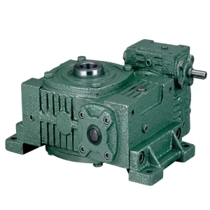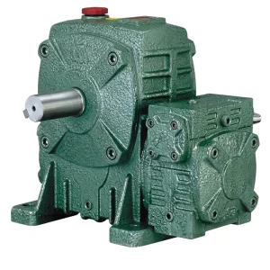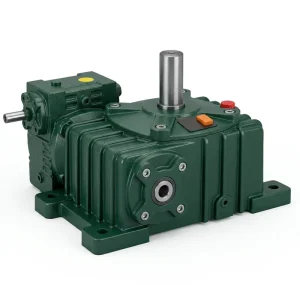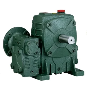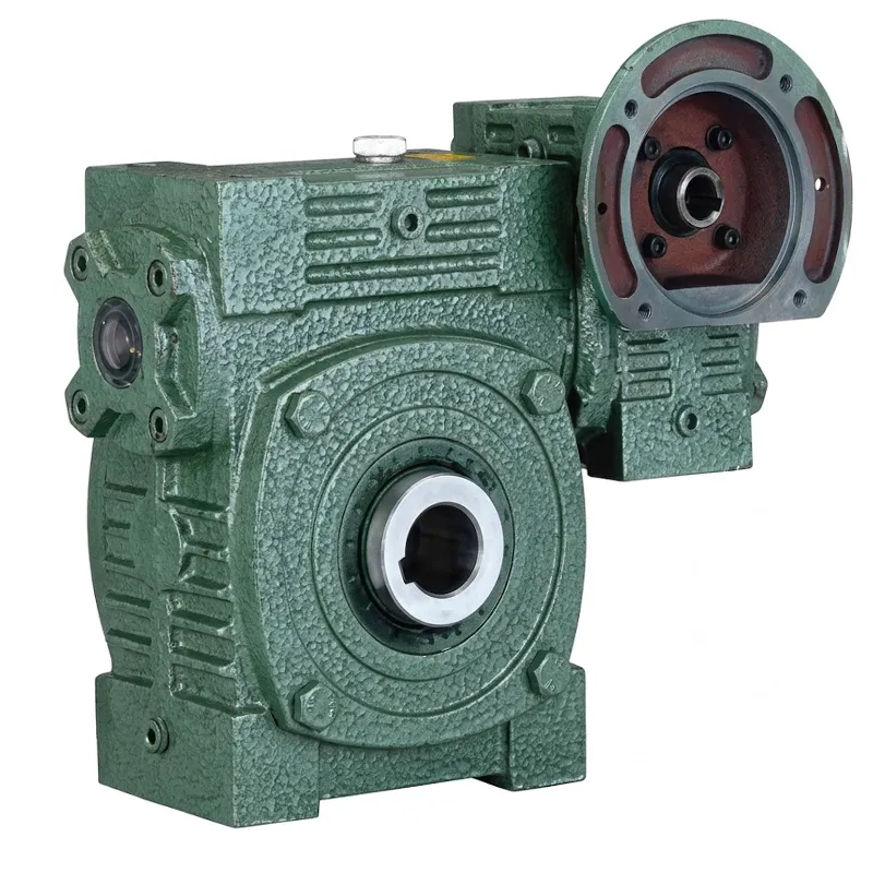
EP-WPWEDK ตัวลดความเร็วสองระดับ
EP-WPWEDK คือเกียร์ทดรอบแบบหนอนคู่ที่มีคุณสมบัติเด่นที่พบได้น้อยมากในรุ่นเดียวกัน นั่นคือ หน้าสัมผัสของมอเตอร์ที่ขึ้นรูปโดยตรงบนตัวเรือน รวมกับรูส่งออกกลวงที่รับเพลาขับได้โดยไม่ต้องใช้ข้อต่อแยกต่างหาก ข้อดีสองประการนี้ — การติดตั้งมอเตอร์โดยตรงและการส่งออกผ่านเพลา — ทำให้ WPWEDK เป็นเกียร์ทดรอบแบบสองความเร็วที่ติดตั้งง่ายที่สุดในตระกูล WPWED กำลังไฟฟ้าขาเข้ามีตั้งแต่ 0.12 กิโลวัตต์ในเฟรมขนาดกะทัดรัด 40-70 ไปจนถึง 5.5 กิโลวัตต์ในเฟรมขนาดใหญ่ 155-250 โดยมีน้ำหนักตั้งแต่ 18 กิโลกรัมในรุ่นที่เบาที่สุดไปจนถึง 450 กิโลกรัมในรุ่นที่หนักที่สุด ทำให้วิศวกรจัดซื้อมีผลิตภัณฑ์ตระกูลเดียวที่ปรับขนาดได้ตั้งแต่ระบบอัตโนมัติขนาดเล็กไปจนถึงไดรฟ์กระบวนการหนักแบบต่อเนื่อง
ระบบเฟืองตัวหนอนคู่แบบเรียงซ้อนให้ผลการลดรอบโดยรวมระหว่าง 1/200 ถึง 1/900 จากความเร็วรอบอินพุตของมอเตอร์ AC มาตรฐาน โดยไม่จำเป็นต้องมีส่วนประกอบตัวกลางภายนอก มีตัวเลือกทิศทางเพลาสามแบบ — A, B และ C — ครอบคลุมทั้งแบบรูเดี่ยวและแบบรูคู่ตรงข้ามกัน รองรับรูปทรงเรขาคณิตของเครื่องจักรได้หลากหลาย WPWEDK เหมาะอย่างยิ่งสำหรับผู้ที่ออกแบบเครื่องจักรต้องการติดตั้งมอเตอร์โดยตรงกับหน้าเกียร์ (โดยไม่ต้องใช้ขายึดมอเตอร์และข้อต่อแยกต่างหาก) ส่งเพลาขับผ่านรูเอาต์พุต และได้อัตราการลดรอบสูงมาก ซึ่งมีเพียงระบบขับเคลื่อนเฟืองตัวหนอนคู่เท่านั้นที่สามารถทำได้ในขนาดที่เทียบเท่ากัน
ระบบส่งกำลังอุตสาหกรรม · ซีรีส์ความเร็วคู่
EP-WPWEDK ตัวลดความเร็วสองระดับ
รูกลวงแบบติดตั้งหน้าแปลน ตัวลดความเร็วสองเท่า ซึ่งประกอบด้วยชุดเฟืองตัวหนอนสองชุดอยู่ภายในตัวเรือนเหล็กหล่อเสริมเหล็กที่มีร่อง พร้อมหน้าแปลนมอเตอร์ในตัว มีให้เลือกตั้งแต่รุ่นเริ่มต้นน้ำหนัก 18 กก. ไปจนถึงรุ่นสำหรับงานหนักน้ำหนัก 450 กก. และให้อัตราส่วนลดเกียร์ตัวหนอนสูงสุดถึง 1/900 สำหรับงานขับเคลื่อนอุตสาหกรรมความเร็วต่ำที่ต้องการประสิทธิภาพสูงทั่วโลก
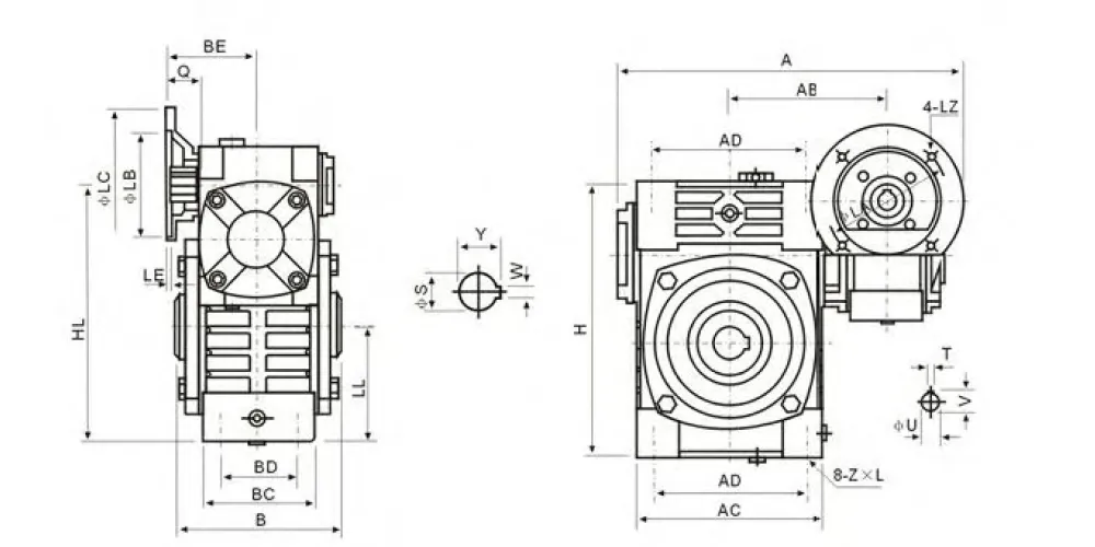
ข้อมูลจำเพาะทางเทคนิค — ชุดเกียร์ทดรอบสองความเร็ว รุ่น EP-WPWEDK
ขนาดภายนอกทั้งหมดระบุเป็นมิลลิเมตร น้ำหนักระบุเป็นกิโลกรัม ระยะห่างระหว่างรูยึดหน้าแปลนมอเตอร์ตามที่ระบุไว้ ขนาดเพลาอินพุต T×V และขนาดรูเอาต์พุต W×Y ระบุเป็นมิลลิเมตร
| ตัวลดความเร็วสองเท่า
ขนาด |
กำลังไฟฟ้า (กิโลวัตต์) | อัตราส่วน | เอ | เอบี | บี | เป็น | เอซี | บีซี | โฆษณา | บีดี | เอชแอล | แอลแอล | ชม | ซ×แอล | หน้าแปลนมอเตอร์ (LA×LB) | รูทางเข้า T×V (มม.) | ขนาดรูทางออก กว้าง×ยาว (มม.) | น้ำหนัก (กก.) |
|---|---|---|---|---|---|---|---|---|---|---|---|---|---|---|---|---|---|---|
| 40-70 | 0.12 | 1/200 | 314 | 153 | 130 | 75 | 152 | 86 | 125 | 65 | 200 | 90 | 215 | M10×25 | 115×95 | 4×12.8 | 8×33.3 | 18 |
| 50-80 | 0.18 | 1/200 | 314 | 144 | 150 | 83 | 169 | 102 | 140 | 70 | 235 | 105 | 250 | M12×28 | 115×95 | 4×12.8 | 10×38.3 | 28 |
| 60-100 | 0.37 | 1/200 | 387 | 175 | 160 | 91 | 216 | 117 | 180 | 90 | 290 | 130 | 310 | M12×30 | 130×110 | 5×16.3 | 12×43.3 | 44 |
| 70-120 | 0.37 | 1/300 | 425 | 193 | 175 | 109 | 256 | 124 | 220 | 100 | 345 | 155 | 370 | เอ็ม14×32 | 130×110 | 5×16.3 | 14×48.8 | 66 |
| 0.75 | 1/400 | 445 | 193 | 175 | 111 | 256 | 124 | 220 | 100 | 345 | 155 | 370 | เอ็ม14×32 | 165×130 | 6×21.8 | 14×48.8 | 66 | |
| 80-135 | 0.75 | 1/500 | 499 | 226 | 210 | 125 | 296 | 147 | 260 | 110 | 400 | 185 | 425 | เอ็ม16×35 | 165×130 | 6×21.8 | 18×64.4 | 101 |
| 1.5 | 1/600 | 499 | 226 | 210 | 125 | 296 | 147 | 260 | 110 | 400 | 185 | 425 | เอ็ม16×35 | 165×130 | 8×27.3 | 18×64.4 | 101 | |
| 100-155 | 1.5 | 1/800 | 570 | 269 | 256 | 148 | 345 | 185 | 280 | 120 | 458 | 203 | 461 | เอ็ม16×35 | 165×130 | 8×27.3 | 20×74.9 | 139 |
| 120-175 | 2.2 | 1/900 | 631 | 287 | 282 | 181 | 374 | 192 | 320 | 140 | 518 | 223 | 521 | เอ็ม16×35 | 215×180 | 8×31.3 | 22×85.4 | 196 |
| 3.0 | 1/900 | 631 | 287 | 282 | 181 | 374 | 192 | 320 | 140 | 518 | 223 | 521 | เอ็ม16×35 | 215×180 | 8×31.3 | 22×85.4 | 196 | |
| 135-200 | 3.0 | —— | 680 | 318 | 320 | 202 | 412 | 230 | 360 | 150 | 580 | 245 | 575 | เอ็ม20×36 | 215×180 | 8×31.3 | 22×90.4 | 285 |
| 4.0 | —— | 680 | 318 | 320 | 202 | 412 | 230 | 360 | 150 | 580 | 245 | 575 | เอ็ม20×36 | 215×180 | 8×31.3 | 22×90.4 | 285 | |
| 155-250 | 5.5 | —— | 815 | 380 | 400 | 247 | 500 | 285 | 420 | 180 | 705 | 300 | 700 | เอ็ม24×42 | 265×230 | 10×41.3 | 28×116.4 | 450 |
ขนาดวงกลมรูยึดหน้าแปลนมอเตอร์ระบุเป็น LA×LB (เส้นผ่านศูนย์กลางวงกลมระยะห่าง × เส้นผ่านศูนย์กลางวงกลมรูยึด, มม.) ขนาดรูทางเข้า T×V = ความกว้างร่องลิ่ม × ความลึกร่องลิ่ม ขนาดรูทางออก W×Y = เส้นผ่านศูนย์กลางรู × ความลึกรู โปรดติดต่อทีมวิศวกรของเราสำหรับขนาดรูที่ไม่เป็นมาตรฐานและอัตราส่วนที่กำหนดเอง
ข้อดีสำคัญ 5 ประการของเกียร์ทดรอบสองความเร็ว EP-WPWEDK
ฐานยึดมอเตอร์แบบรวม
ตัวเรือนเกียร์ทดรอบสองความเร็ว WPWEDK มีหน้าหน้าแปลนมอเตอร์ที่ผ่านการกลึงมาเป็นคุณสมบัติมาตรฐาน ทำให้สามารถติดตั้งมอเตอร์ IEC ที่เข้ากันได้โดยตรงกับเกียร์โดยไม่ต้องใช้อะแดปเตอร์ ซึ่งช่วยลดความเสี่ยงจากการเยื้องศูนย์ของเพลาที่เกิดจากแผ่นยึดมอเตอร์แยกต่างหาก และลดความสูงโดยรวมของชุดขับเคลื่อนเมื่อติดตั้ง ซึ่งเป็นข้อได้เปรียบที่สำคัญในฐานเครื่องจักรที่มีพื้นที่จำกัดและการออกแบบตู้แบบปิด
เอาต์พุตแบบกลวงทะลุ
รูทางออกกลวงช่วยให้เพลาขับผ่านเข้าไปในกล่องเกียร์ได้โดยตรง ทำให้ไม่จำเป็นต้องใช้อุปกรณ์เชื่อมต่อทางออกใดๆ การออกแบบนี้ช่วยลดขนาดโดยรวมตามแนวแกนของระบบส่งกำลังได้อย่างมาก เมื่อเทียบกับชุดเพลาตันที่ติดตั้งข้อต่อแบบก้ามปูหรือแบบจาน และช่วยขจัดสาเหตุหลักประการหนึ่งของการเยื้องศูนย์ในการใช้งานเฟืองตัวหนอนอัตราทดสูงในเครื่องจักรอุตสาหกรรมที่เคลื่อนที่ช้า
อัตราส่วนถึง 1/900 ในหน่วยเดียว
ชุดเฟืองตัวหนอนสองชุดที่เรียงต่อกันภายในตัวเรือนเดียวกัน ทำให้ได้อัตราส่วนโดยรวมระหว่าง 1/200 ถึง 1/900 ซึ่งเป็นช่วงที่หากใช้กรรมวิธีแบบดั้งเดิมจะต้องใช้เกียร์บ็อกซ์แบบขั้นตอนเดียวขนาดใหญ่มาก หรือใช้สองชุดแยกกันต่อกัน สำหรับผู้ผลิตเครื่องจักรที่ต้องการความเร็วรอบต่ำมาก WPWEDK คือโซลูชันที่มีประสิทธิภาพด้านพื้นที่มากที่สุดเท่าที่จะทำได้ในปัจจุบัน เกียร์หนอนทดรอบ สถาปัตยกรรม.
ระบบล็อคตัวเองโดยธรรมชาติเมื่อรับน้ำหนัก
รูปทรงเกลียวหนอนทำให้เกิดการล็อคตัวเองโดยธรรมชาติ กล่าวคือ แรงที่กระทำต่อเพลาส่งออกไม่สามารถทำให้เกลียวหนอนหมุนย้อนกลับได้ ซึ่งเป็นประโยชน์อย่างยิ่งในการใช้งานกับกลไกเปิดปิดประตู ลิฟต์แนวตั้ง และการใช้งานที่ต้องการแรงดึงยึด ซึ่งหากไฟฟ้าดับจะต้องไม่ทำให้เกิดการเคลื่อนไหวที่ควบคุมไม่ได้ คุณลักษณะนี้ถูกสร้างขึ้นในรูปทรงของตัวขับ ไม่ใช่ส่วนเสริมที่จัดหาแยกต่างหาก และไม่จำเป็นต้องติดตั้งเบรกยึดเพิ่มเติมในการใช้งานส่วนใหญ่ในประเภทนี้
18 กก. ถึง 450 กก. — ครอบคลุมทุกช่วงน้ำหนัก
ขนาดเฟรมทั้งเก้าขนาด ตั้งแต่ 40-70 ไปจนถึง 155-250 ครอบคลุมทุกระดับน้ำหนักและแรงบิดภายในกลุ่มเครื่องกวนแบบสองขั้นตอน นักออกแบบเครื่องจักรสามารถกำหนดกลุ่มผลิตภัณฑ์เดียวได้ตลอดทั้งสายผลิตภัณฑ์ ตั้งแต่เครื่องกวนขนาดเล็กในห้องปฏิบัติการไปจนถึงเครื่องผสมวัสดุขนาดใหญ่ และเข้าถึงขนาดอินเทอร์เฟซ เอกสารประกอบ และกลยุทธ์อะไหล่ที่สม่ำเสมอจากแหล่งเดียว แทนที่จะต้องจัดการกับซัพพลายเออร์หลายราย
หลักการทำงานของเกียร์ทดรอบแบบหนอนคู่
กำลังไฟฟ้าขาเข้าผ่านหน้าแปลนมอเตอร์ IEC มาตรฐานที่ยึดติดกับพื้นผิวที่ผ่านการกลึงของตัวเรือนเกียร์ทดรอบสองความเร็ว WPWEDK เพลาของมอเตอร์จะขบกับเฟืองตัวหนอนหลักผ่านการเชื่อมต่อแบบร่องลิ่มบนเพลาที่มีรูขาเข้า (ขนาด T×V ในตารางข้อมูลจำเพาะ) เฟืองตัวหนอนหลักจะขบกันที่มุม 90° กับล้อเฟืองตัวหนอนฟอสฟอรัสบรอนซ์หลัก แปลงการหมุนความเร็วสูงของมอเตอร์ให้เป็นการหมุนที่ลดลงในขั้นแรกบนเพลาตัวกลาง เพลาตัวกลางจะรับเฟืองตัวหนอนรอง ซึ่งจะขับเคลื่อนล้อเฟืองตัวหนอนรองต่อไป — ล้อเฟืองนี้ยึดติดกับเพลาที่มีรูส่งออกกลวง ทำให้ได้ความเร็วเอาต์พุตสุดท้ายที่ลดลงอย่างมาก
เนื่องจากอัตราส่วนโดยรวมเป็นผลคูณของอัตราส่วนในแต่ละขั้นทั้งสอง ทำให้ตัวลดความเร็วสองระดับ WPWEDK สามารถลดอัตราทดเกียร์ได้ในระดับที่แทบจะเป็นไปไม่ได้เลยหากใช้เฟืองตัวหนอนและล้อเพียงคู่เดียวที่มีขนาดตัวเรือนเท่ากัน การจัดเรียงนี้มีประสิทธิภาพเทียบเท่ากับ... เกียร์หนอนลดรอบสองชั้น ในความหมายทางวิศวกรรมอย่างแท้จริง: ชุดลดเกียร์สองชุดที่ทำงานแยกจากกันทางกลไก ต่อกันเป็นอนุกรม โดยใช้ถังเก็บน้ำมันหล่อลื่นร่วมกัน และใช้ตัวเรือนเหล็กหล่อสีเทาแบบมีครีบร่วมกัน ซึ่งให้ทั้งความแข็งแรงของโครงสร้างและพื้นที่ผิวที่เพียงพอสำหรับการระบายความร้อนในรอบการทำงานมาตรฐาน ประสิทธิภาพของชุดลดเกียร์นี้ โดยทั่วไปอยู่ในช่วง 45–65% ขึ้นอยู่กับอัตราส่วนและภาระ หมายความว่าสำหรับการใช้งานกำลังสูงอย่างต่อเนื่อง ต้องตรวจสอบพิกัดความร้อนควบคู่ไปกับพิกัดแรงบิดทางกลก่อนที่จะยืนยันขนาดเฟรม
รูทางออกกลวงของ ตัวลดความเร็วสองเท่า ชิ้นส่วนได้รับการกลึงให้ได้ความคลาดเคลื่อนระดับ H7 ทำให้มั่นใจได้ถึงการประกอบที่แน่นหนาหรือการเปลี่ยนผ่านที่เชื่อถือได้กับเส้นผ่านศูนย์กลางเพลามาตรฐาน ขนาดรูเพลาส่งออก W×Y (เส้นผ่านศูนย์กลางรู × ความลึกของรูในหน่วยมิลลิเมตร ตามที่ระบุในตารางพารามิเตอร์) กำหนดขนาดเพลาขับสูงสุดที่ตัวเครื่องสามารถรองรับได้ ขนาดร่องลิ่มทั้งในรูทางเข้า (Q, U, T×V) และรูทางออก (S, W×Y) ได้รับการกำหนดมาตรฐานไว้ในตัวลดความเร็วสองระดับ WPWEDK ทั้งหมด ทำให้การเลือกเพลาและลิ่มในขั้นตอนการออกแบบง่ายขึ้น
ข้อมูลจำเพาะวัสดุและคุณภาพการผลิตของเกียร์ทดรอบสองความเร็ว
ตัวเรือนของชุดลดความเร็วสองระดับ WPWEDK ผลิตจากเหล็กหล่อสีเทาคุณภาพสูง ซึ่งได้รับการคัดเลือกเนื่องจากมีคุณสมบัติที่ดีเยี่ยมทั้งด้านการขึ้นรูป การลดแรงสั่นสะเทือน และความเสถียรของขนาดภายใต้ภาระความร้อนแบบวัฏจักรที่เกิดขึ้นจากการทำงานในอุตสาหกรรมอย่างต่อเนื่อง ขนาดเฟรมที่หนักกว่า โดยเฉพาะขนาด 135-200 และ 155-250 สามารถเลือกใช้เหล็กดัดหรือเหล็กหล่อได้ ในกรณีที่ต้องการความทนทานต่อแรงกระแทกสูงหรืออุณหภูมิแวดล้อมสูงขึ้น ซึ่งทำให้เกินขีดจำกัดด้านความร้อนและเชิงกลของเหล็กหล่อสีเทามาตรฐาน ตัวเรือนอะลูมิเนียมหล่อก็มีให้เลือกใช้สำหรับขนาดเฟรมที่เบากว่า ในการใช้งานที่น้ำหนักโดยรวมของชุดขับเคลื่อนเป็นข้อจำกัด เช่น ชุดขับเคลื่อนเครื่องกวนแบบติดตั้งเหนือศีรษะในอุตสาหกรรมอาหาร
เพลาตัวหนอนทั้งสองข้างผลิตจากเหล็กกล้าชุบแข็งผิว 20CrMnTi หรือโลหะผสมที่เทียบเท่า โดยผ่านกระบวนการตีขึ้นรูปและกลึงขึ้นรูป อบชุบแข็งจนมีความหนาของชั้นผิว 0.8–1.2 มม. และชุบแข็งจนมีความแข็ง 58–62 HRC ที่ด้านข้างเกลียวตัวหนอน การเจียรเกลียวหลังการอบชุบความร้อนทำให้ด้านข้างเกลียวมีความแม่นยำตามมาตรฐาน DIN 3975 ซึ่งเป็นตัวกำหนดการกระจายความเค้นสัมผัสและระดับเสียงขณะใช้งานโดยตรง ล้อตัวหนอนผลิตจากโลหะผสมบรอนซ์ฟอสฟอรัสดีบุกสูง (โดยทั่วไปเทียบเท่า ZCuSn10P1) โดยวิธีการหล่อแบบเหวี่ยงหนีศูนย์กลาง ขึ้นรูปให้ได้รูปทรงที่พอดีกับเพลา และติดตั้งเข้ากับเพลาโดยใช้ลิ่มขนาน การจับคู่เหล็กกับบรอนซ์นี้เป็นมาตรฐานทั่วไป ผู้ผลิตเกียร์ทดรอบแบบหนอน เป็นที่ยอมรับในระดับสากล และมีคุณสมบัติที่ได้รับการบันทึกไว้อย่างดี ทั้งในด้านพฤติกรรมการใช้งานในช่วงเริ่มต้นที่ควบคุมได้ และค่าสัมประสิทธิ์แรงเสียดทานที่คงที่ในระยะยาว
รูส่งกำลังแบบกลวงได้รับการตกแต่งให้มีความคลาดเคลื่อนตามมาตรฐาน H7 และร่องลิ่มของรูเป็นไปตามมาตรฐาน JS9 ซึ่งสอดคล้องกับแนวทางการประกอบตามมาตรฐาน ISO 286 สำหรับการประกอบแบบกดเบาหรือการเลื่อนด้วยเพลามาตรฐานทั่วไป ตลับลูกปืนเม็ดกลมร่องลึกถูกใช้ที่เพลาตัวหนอนหลัก และตลับลูกปืนลูกกลิ้งเรียวหรือแบบสัมผัสเชิงมุมถูกใช้ที่ตำแหน่งกลางและตำแหน่งส่งออกเพื่อรองรับแรงโหลดทั้งแนวรัศมีและแนวแกนที่เกิดขึ้นเมื่อเพลาขับส่งผ่านทั้งแรงบิดและแรงดัดผ่านรู ระบบสีภายนอก — สีรองพื้นและสีทับหน้า — มีให้เลือกในสีเขียวมาตรฐาน และในสีขาวหรือสีน้ำเงินสำหรับโรงงานที่การกำหนดรหัสสีของระบบขับเคลื่อนสนับสนุนโปรแกรมการบำรุงรักษาหรือความปลอดภัย
สถานการณ์การใช้งานของตัวลดความเร็วสองเท่า
WPWEDK ตัวลดความเร็วสองเท่า เหมาะอย่างยิ่งสำหรับงานที่โครงสร้างเครื่องจักรได้รับประโยชน์จากการที่มอเตอร์ยึดติดกับหน้าเกียร์โดยตรง และเพลาขับผ่านรูทางออก ซึ่งเป็นการกำหนดค่าที่ช่วยลดชิ้นส่วนเชื่อมต่อสองชิ้น และลดจำนวนการตรวจสอบการจัดแนวโครงสร้างระหว่างการติดตั้งและการบำรุงรักษา ต่อไปนี้คือตัวอย่างการใช้งานที่มีปริมาณมากที่สุดในกลุ่มลูกค้าทั่วโลกของเรา
🌀 เครื่องผสมแบบพายและริบบิ้น
เครื่องผสมผงขนาดใหญ่ เครื่องผสมแบบริบบิ้น และเครื่องอบแห้งแบบใบพัดที่ใช้ในอุตสาหกรรมยา การแปรรูปอาหาร และเคมีภัณฑ์ จะติดตั้ง WPWEDK เข้ากับโครงเครื่องผสมโดยตรง โดยยึดมอเตอร์เข้ากับหน้าแปลนของเกียร์ อัตรากำลังสูงช่วยให้เพลาคนกวนหมุนด้วยความเร็วรอบต่ำมาก ซึ่งเป็นความเร็วรอบที่กระบวนการเหล่านี้ต้องการ โดยทั่วไปอยู่ที่ 3–20 รอบต่อนาที ในขณะที่รูภายในกลวงช่วยให้เพลาของเครื่องผสมสามารถติดตั้งได้โดยไม่ต้องใช้ข้อต่อภายนอก ซึ่งจะทำให้การซีลเพลาแบบปิดสนิทซึ่งพบได้ทั่วไปในรุ่นที่ใช้ในสภาพแวดล้อมที่ถูกสุขอนามัยหรืออันตรายในเนเธอร์แลนด์และสหราชอาณาจักรมีความซับซ้อนมากขึ้น
🏗️ ชุดขับเคลื่อนเสริมสำหรับเครนและรอก
ระบบขับเคลื่อนเสริมสำหรับการหมุนด้วยความเร็วต่ำ รางเลื่อนดรัมสายเคเบิล และแท่นเข้าถึงเพื่อการบำรุงรักษาบนเครนเหนือศีรษะในท่าเรือของออสเตรเลียและโรงงานเหล็กของบราซิล ใช้คุณสมบัติการล็อคตัวเองของ WPWEDK เพื่อรักษาระตำแหน่งภายใต้น้ำหนักเมื่อไม่ได้จ่ายไฟ เกียร์ทดรอบแบบเฟืองตัวหนอนสำหรับงานหนัก ในขนาดเฟรม 120-175 และ 135-200 สามารถรับแรงรัศมีต่อเนื่องที่เกิดจากงานเหล่านี้ได้โดยไม่เกิดความล้าของแบริ่งตลอดอายุการใช้งานทั่วไป 15 ปี ซึ่งเป็นอายุการใช้งานที่คาดหวังสำหรับระบบช่วยยกของเครน
🌾 การแปรรูปอาหารสัตว์และพืชอาหารสัตว์
เครื่องพลิกหญ้าหมัก เครื่องลำเลียงผสมอาหารสัตว์ และสายพานลำเลียงป้อนเครื่องอัดเม็ดในฟาร์มโคนมและฟาร์มปศุสัตว์ในแคนาดาและออสเตรเลีย ทำงานภายใต้แรงกระแทกเป็นช่วงๆ จากการอุดตันและการอัดแน่นของวัสดุ ตัวเรือนหล่อขึ้นรูปหนาและที่นั่งแบริ่งขนาดใหญ่ของ WPWEDK สามารถรับมือกับภาระเกินพิกัดชั่วคราวเหล่านี้ได้อย่างน่าเชื่อถือตลอดวงจรการทำงานตามฤดูกาล และหน้าแปลนมอเตอร์แบบรวมช่วยให้การเปลี่ยนเกียร์ทำได้ง่ายขึ้นในช่วงเวลาการบำรุงรักษาในฤดูเก็บเกี่ยว ซึ่งจำเป็นต้องลดเวลาหยุดทำงานให้น้อยที่สุด
⚙️ ระบบขับเคลื่อนท้ายสายพานลำเลียงความเร็วต่ำ
สายพานลำเลียงแบบบิน สายพานลำเลียงแบบกลุ่ม และสายพานลำเลียงแบบโซ่ลากใต้ดินในอุตสาหกรรมเหมืองแร่และวัสดุก่อสร้าง ล้วนอาศัยเทคโนโลยีของ WPWEDK เกียร์หนอนแรงบิดสูง ส่งออกด้วยความเร็วรอบเพลาต่ำมาก เพื่อให้มั่นใจได้ว่าการเคลื่อนที่ของผลิตภัณฑ์เป็นไปอย่างควบคุมได้โดยไม่ลื่นไถลหรือติดขัด รูภายในกลวงช่วยให้รับเพลาท้ายของสายพานลำเลียงได้อย่างสะดวก และสามารถติดตั้งเกียร์บ็อกซ์บนโครงดรัมท้ายได้โดยไม่ต้องมีโครงสร้างรองรับมอเตอร์แยกต่างหากที่ด้านใดด้านหนึ่งของสายพานลำเลียง ในการดำเนินงานแปรรูปแร่ในเกาหลีใต้และโคลอมเบีย
🚰 ตัวขับปั๊มและวาล์ว
ชุดขับปั๊มความเร็วต่ำสำหรับของเหลวหนืด เช่น กากน้ำตาล สารละลายกาว และยางมะตอย รวมถึงกลไกตัวขับวาล์วแบบหลายรอบในโรงกลั่นและโรงบำบัดน้ำเสีย ใช้เฟรม WPWEDK Double Speed Reducer ขนาดเล็กกว่า (40-70 ถึง 80-135) ซึ่ง... เกียร์หนอนแบบเอาต์พุตคู่ ให้ความเร็วเอาต์พุตที่แม่นยำและเสถียร ซึ่งตัวควบคุมกระบวนการแบบวงเปิดสามารถใช้งานได้อย่างมั่นใจโดยไม่ต้องใช้การป้อนกลับจากตัวเข้ารหัส เอาต์พุตแบบล็อคตัวเองช่วยรักษาระตำแหน่งของวาล์วได้อย่างน่าเชื่อถือในระหว่างที่ไฟฟ้าดับ ซึ่งเป็นข้อกำหนดการทำงานที่สำคัญอย่างยิ่งในการติดตั้งวาล์วปิดกั้นที่ได้มาตรฐานความปลอดภัยทั่วสหราชอาณาจักรและเนเธอร์แลนด์
เกี่ยวกับเรา - ผู้ผลิตเกียร์ทดรอบสองความเร็ว
ประสบการณ์การผลิตด้านระบบส่งกำลังเชิงกลกว่าสิบปีเป็นพื้นฐานในการตัดสินใจทุกอย่างของเรา ตั้งแต่การคัดเลือกวัตถุดิบไปจนถึงการตรวจสอบแรงบิดในการประกอบขั้นสุดท้าย ขอบเขตการผลิตของเราครอบคลุมถึงเกียร์บ็อกซ์สำหรับงานเกษตรกรรม ตัวลดความเร็วแบบหนอนรวมถึงระบบขับเคลื่อนแบบดาวเคราะห์ เพลาส่งกำลัง กระบอกไฮดรอลิก เฟืองความแม่นยำ โซ่ลูกกลิ้ง เฟืองโซ่ และมอเตอร์ไฟฟ้า ทำให้เรามีความเข้าใจในระดับระบบเพื่อให้คำแนะนำเกี่ยวกับวิธีการใช้งาน เกียร์ทดรอบหนอนสองความเร็ว เป็นการบูรณาการเข้ากับระบบขับเคลื่อนของเครื่องจักร แทนที่จะขายชิ้นส่วนจากแคตตาล็อกแยกต่างหาก
กระบวนการผลิตดำเนินการภายใต้มาตรฐาน ISO 9001:2015 ครอบคลุมทุกขั้นตอน ตั้งแต่การตรวจสอบวัสดุขาเข้า การหล่อ การกลึง การอบชุบความร้อน การประกอบ และการทดสอบก่อนการจัดส่ง วัสดุตัวเรือนที่ใช้ได้ ได้แก่ เหล็กดัด เหล็กหล่อ เหล็กหล่อ เหล็กหล่อความแม่นยำสูง และอลูมิเนียมหล่อ ซึ่งทั้งหมดผลิตหรือจัดหาภายใต้ข้อกำหนดวัสดุที่บันทึกไว้พร้อมใบรับรองจากโรงงานที่ตรวจสอบย้อนกลับได้ ชิ้นส่วนเกียร์ เช่น เพลาหนอน ล้อหนอน เฟือง สไปลซ์ และหนอน ผลิตขึ้นภายในบริษัทหรือภายใต้ข้อตกลงการว่าจ้างช่วงที่ควบคุมอย่างใกล้ชิด โดยมีการเก็บรักษาบันทึกการตรวจสอบขนาดสำหรับแต่ละชุดการผลิต ข้อกำหนดเฉพาะที่กำหนดเอง เช่น ขนาดรูที่ไม่เป็นมาตรฐาน อัตราส่วนพิเศษ ฐานยึดที่ดัดแปลง และสีที่ไม่ตรงกับในแคตตาล็อก ได้รับการยอมรับเป็นคำขอทางวิศวกรรมทั่วไปสำหรับขนาดเฟรม WPWEDK ทุกขนาด
เวิร์กช็อป



ผลิตภัณฑ์และส่วนประกอบระบบที่เกี่ยวข้อง
หน้าแปลนมอเตอร์แบบรวมของ WPWEDK ออกแบบมาเพื่อรองรับมอเตอร์เฟรมมาตรฐาน IEC ได้โดยตรง และรองรับการลดเกียร์เดี่ยวแบบเต็มรูปแบบ เกียร์ทดรอบหนอน ช่วงราคานี้ครอบคลุมการใช้งานที่มีอัตราส่วนต่ำกว่า ซึ่งมักพบควบคู่ไปกับชุดสองขั้นตอนในแคตตาล็อกของโรงงานส่วนใหญ่ การจัดหาทั้งสองอย่างจากโรงงานเดียวกันช่วยลดความซับซ้อนของเอกสาร ลดความผันแปรของระยะเวลานำส่ง และรับประกันความเข้ากันได้ของขนาดหน้าแปลนโดยไม่ต้องใช้อะแดปเตอร์ที่วัดหน้างาน

มอเตอร์ไฟฟ้า
มอเตอร์เหนี่ยวนำแบบเฟรม IEC ในรูปแบบหน้าแปลน B5 และ B14 ขนาดพอดีกับขนาดหน้าแปลนขาเข้าของ WPWEDK ตลอดช่วงกำลังไฟฟ้า 0.12 kW ถึง 5.5 kW เมื่อสั่งซื้อเป็นชุดที่เข้ากัน มอเตอร์ไฟฟ้า ตัวลดเกียร์หนอนสองความเร็ว ในการประกอบชิ้นส่วน การจัดแนวของเพลามอเตอร์กับรูทางเข้าของเกียร์ และการล็อกของลิ่ม จะได้รับการตรวจสอบจากโรงงานก่อนการจัดส่ง ซึ่งช่วยลดความเสี่ยงของข้อผิดพลาดในการประกอบที่หน้างาน ซึ่งมักเกิดขึ้นเมื่อจัดหามอเตอร์และเกียร์แยกกัน

ช่วงเกียร์หนอนแบบขั้นเดียว
สำหรับงานที่ต้องการความเร็วในอัตราส่วนระหว่าง 1/5 ถึง 1/100 นั้น ตระกูล NMRV, WP และ WPS แบบลดรอบเดียวจะให้โซลูชันที่กะทัดรัดและมีประสิทธิภาพมากกว่า WPWEDK แบบสองรอบ อุปกรณ์ลดขนาดหนอนคุณภาพสูง และ ตัวลดจำนวนหนอน nmrv สายการผลิตใช้มาตรฐานหน้าแปลนมอเตอร์แบบเดียวกันกับ WPWEDK ทำให้การระบุโซลูชันที่มีต้นทุนต่ำที่สุดในแต่ละจุดอัตราส่วนของผลิตภัณฑ์ทำได้ง่าย ดูรายละเอียดเพิ่มเติมได้ในเกียร์หนอนแบบครบชุด
คำถามที่พบบ่อย
คำถามที่ 1 — ข้อดีของการใช้หน้าแปลนมอเตอร์แบบรวมอยู่ในตัวของชุดลดความเร็วสองระดับ เมื่อเทียบกับการใช้ขายึดมอเตอร์แยกต่างหาก สำหรับการใช้งานในระบบขับเคลื่อนเครื่องผสมในโรงงานแปรรูปอาหารในสหราชอาณาจักรคืออะไร?
หน้าแปลนมอเตอร์แบบรวมที่กลึงขึ้นโดยตรงในตัวเรือนเกียร์ช่วยรักษาความเที่ยงตรงของเพลามอเตอร์กับเฟืองตัวหนอนให้อยู่ภายในค่าความคลาดเคลื่อนของรูในตัวเรือน ซึ่งโดยทั่วไปจะดีกว่า 0.05 มม. TIR ตัวยึดแยกต่างหากจะทำให้เกิดค่าความคลาดเคลื่อนเพิ่มเติมที่ข้อต่อสลักเกลียวแต่ละจุด — ตัวยึดกับเกียร์บ็อกซ์, มอเตอร์กับตัวยึด — ซึ่งอาจส่งผลให้เกิดแรงกดในแนวรัศมีบนตลับลูกปืนเฟืองตัวหนอนหลักเนื่องจากการจัดแนวที่ไม่ถูกต้อง ในการใช้งานที่เกี่ยวข้องกับอาหารในสหราชอาณาจักร ซึ่งต้องใช้ตัวเรือนมอเตอร์ที่มีระดับการป้องกัน IP65 หรือสูงกว่าที่ประกบเข้ากับเกียร์บ็อกซ์ได้อย่างแนบสนิท หน้าแปลนแบบรวมยังช่วยลดความซับซ้อนของวิศวกรรมข้อต่อแบบปิดผนึกที่ส่วนต่อประสานระหว่างมอเตอร์และเกียร์บ็อกซ์โดยการลดจำนวนพื้นผิวการปิดผนึกที่แยกจากกัน
Q2 — ฉันจะกำหนดขนาดเฟรมตัวลดความเร็วคู่ WPWEDK ที่เหมาะสมสำหรับเครื่องผสมแบบริบบิ้นที่ทำงานที่ความเร็วรอบ 5 RPM ในโรงงานผสมยาในประเทศเนเธอร์แลนด์ได้อย่างไร?
เริ่มต้นด้วยความเร็วของมอเตอร์ — มอเตอร์มาตรฐาน 4 ขั้ว 50 Hz ทำงานที่ประมาณ 1440 รอบต่อนาที — แล้วหารด้วยความเร็วเอาต์พุตที่ต้องการเพื่อให้ได้อัตราส่วนที่ต้องการ: 1440 ÷ 5 = 288 ดังนั้น ตัวลดความเร็วแบบสองระดับ WPWEDK อัตราส่วน 1/300 จึงเป็นตัวเลือกมาตรฐานที่ใกล้เคียงที่สุด ถัดไป คำนวณแรงบิดเอาต์พุตที่เพลาเครื่องปั่นของคุณต้องการที่ 5 รอบต่อนาที และตรวจสอบว่าแรงบิดเอาต์พุตที่กำหนดของขนาดเฟรมที่เลือกนั้นเกินกว่าค่านี้อย่างน้อยด้วยปัจจัยการใช้งานของคุณ (1.25 สำหรับโหลดที่สม่ำเสมอและราบเรียบ 1.5 สำหรับการใช้งานที่แปรผันหรือกลับทิศทางในการผสมแบบเป็นชุดในอุตสาหกรรมยา) สุดท้าย ยืนยันว่าขนาดรูเอาต์พุต W×Y สามารถรองรับเส้นผ่านศูนย์กลางเพลาเครื่องปั่นของคุณได้ โดยมีความยาวของร่องลิ่มที่เพียงพอสำหรับแรงบิดที่ส่งผ่าน
คำถามที่ 3 — การกำหนดทิศทางการหมุนของเพลาแบบใดของตัวลดความเร็วสองระดับ EP-WPWEDK เหมาะสมที่สุดสำหรับเครื่องผสมแบบใบพัดเหนือศีรษะที่ติดตั้งบนถังแปรรูปในโรงงานผลิตนมของออสเตรเลีย?
การจัดวางแบบ A — โดยมีรูส่งกำลังกลวงชี้ลงด้านล่างและหน้าแปลนมอเตอร์อยู่ด้านบน — เป็นการจัดเรียงมาตรฐานสำหรับชุดขับเคลื่อนใบพัดกวนแบบติดตั้งเหนือศีรษะ การจัดวางแบบนี้ทำให้จุดศูนย์ถ่วงของมอเตอร์อยู่เหนือจุดศูนย์ถ่วงของเกียร์โดยตรง ช่วยให้มอเตอร์อยู่ห่างจากน้ำกระเด็นและไอน้ำในกระบวนการผลิต และทำให้รูส่งกำลังกลวงชี้ลงในแนวตั้งเพื่อรับเพลาใบพัดกวนด้วยการยึดร่องลิ่มที่ง่ายที่สุด ในการใช้งานในฟาร์มโคนมของออสเตรเลียซึ่งมีการล้างทำความสะอาดแบบ CIP (clean-in-place) เป็นประจำ การติดตั้งมอเตอร์แบบแนวตั้งด้านบนยังช่วยให้ช่องระบายอากาศของมอเตอร์อยู่ห่างจากน้ำแรงดันสูงที่พ่นไปที่ด้านล่างของเกียร์อีกด้วย
คำถามที่ 4 — เมื่อใดที่เกียร์ทดรอบแบบหนอนคู่จึงเป็นตัวเลือกที่ดีกว่าเกียร์ทดรอบแบบเฟืองเฉียงสำหรับการขับเคลื่อนสายพานลำเลียงความเร็วต่ำในโรงงานแปรรูปวัสดุก่อสร้างในโคลอมเบีย?
เดอะ เกียร์ทดรอบแบบหนอนคู่ ชุดลดความเร็วคู่ WPWEDK มีข้อดีในด้านต้นทุนการซื้อโดยรวม ช่วงอัตราส่วน และระบบล็อคตัวเองในตัวที่อัตราส่วนการลดความเร็วสูงมาก ซึ่งโดยทั่วไปจะสูงกว่า 1/100 ในขณะที่ชุดเฟืองเกลียว-เฟืองเฉียงที่มีอัตราส่วนและความสามารถในการรับแรงบิดเทียบเท่ากันนั้น เป็นการออกแบบหลายขั้นตอนที่ซับซ้อนกว่า มีประสิทธิภาพสูงกว่า (โดยทั่วไป 85–95%) แต่มีต้นทุนต่อหน่วยสูงกว่ามาก มีพื้นที่ติดตั้งมากกว่าในสองหรือสามแกน และไม่มีระบบล็อคตัวเองในตัว หมายความว่าต้องระบุเบรกแยกต่างหากสำหรับสายพานลำเลียงที่เอียง ในกระบวนการแปรรูปวัสดุก่อสร้างในโคลอมเบีย ซึ่งต้นทุนรวมในการเป็นเจ้าของอุปกรณ์นั้นมีความสำคัญอย่างยิ่งต่อประสิทธิภาพที่เกินความจำเป็น ชุดลดความเร็วคู่ WPWEDK จึงเป็นตัวเลือกที่เหมาะสมสำหรับชุดขับท้ายสายพานลำเลียงที่ทำงานที่ความเร็วรอบต่ำกว่า 5 รอบต่อนาที ด้วยความสามารถในการรับแรงบิดที่เพียงพอ เอาต์พุตที่ล็อคตัวเองได้ ราคาที่แข่งขันได้ และการบำรุงรักษาที่ง่าย
Q5 — ควรระบุประเภทสารหล่อลื่นและช่วงเวลาการเปลี่ยนถ่ายอย่างไรสำหรับเกียร์ทดรอบสองความเร็ว WPWEDK ที่ใช้งานในสายการผลิตบรรจุภัณฑ์ในเกาหลีใต้ซึ่งทำงานสองกะในอุณหภูมิแวดล้อมสูง?
สำหรับการทำงานแบบสองกะ โดยมีอุณหภูมิแวดล้อมอยู่ในช่วง 35–45 °C ซึ่งเป็นอุณหภูมิปกติของโรงงานบรรจุภัณฑ์ในเกาหลีใต้ที่ไม่มีเครื่องปรับอากาศในช่วงฤดูร้อน แนะนำให้ใช้น้ำมันเกียร์สังเคราะห์โพลีอัลฟาโอเลฟิน (PAO) ISO VG 220 มากกว่าน้ำมันแร่ น้ำมันสังเคราะห์จะรักษาระดับความหนืดไว้ได้ที่อุณหภูมิการทำงานสูง ลดแรงเสียดทานภายใน และลดอุณหภูมิการทำงานของเกียร์ลง 8–12 °C เมื่อเทียบกับน้ำมันแร่ที่มีความหนืดระดับเดียวกัน ซึ่งจะช่วยยืดอายุการใช้งานของแบริ่งและซีลโดยตรง ระยะเวลาการเปลี่ยนถ่ายน้ำมันสังเคราะห์โดยทั่วไปอยู่ที่ 6,000–8,000 ชั่วโมง เทียบกับ 3,000–4,000 ชั่วโมงสำหรับน้ำมันแร่ภายใต้สภาวะการทำงานเดียวกัน การตรวจสอบซีลกันรั่วทุกครั้งที่เปลี่ยนถ่ายน้ำมันยังคงเป็นกิจกรรมการบำรุงรักษาที่ให้ผลตอบแทนสูงสุด ไม่ว่าจะเป็นน้ำมันประเภทใดก็ตาม
Q6 — ทีมจัดซื้อในบราซิลควรจัดหาตัวลดเกียร์หนอนสองความเร็วแบบทดแทนที่ได้รับการรับรองสำหรับชุดขับเคลื่อนเครื่องกวนที่มีอยู่เดิมจากที่ใด โดยมีแบบร่างขนาดและเอกสารวัสดุครบถ้วน?
แนวทางที่น่าเชื่อถือที่สุดสำหรับการจัดหา เกียร์ทดรอบหนอนสองความเร็วแบบเปลี่ยนทดแทน ในประเทศบราซิล วิธีการที่เหมาะสมที่สุดคือการติดต่อโรงงานผลิตที่ได้รับการรับรองมาตรฐาน ISO 9001:2015 โดยตรง โดยให้ข้อมูลป้ายชื่อของชิ้นส่วนเดิม เช่น ขนาดเฟรม อัตราส่วน กำลังไฟฟ้าขาเข้า ทิศทางเพลา และขนาดที่สำคัญ พร้อมด้วยรูปถ่ายของการจัดวางการติดตั้งและการเชื่อมต่อรูเอาต์พุต ผู้ผลิตที่ได้รับการรับรองจะตรวจสอบความเข้ากันได้ของขนาดกับแบบร่างการผลิต ออกเอกสารยืนยันขนาดอย่างเป็นทางการ และจัดหาใบรับรองวัสดุและบันทึกการตรวจสอบที่จำเป็นภายใต้ขั้นตอนการรับรองผู้จัดจำหน่ายของบราซิลสำหรับอุปกรณ์โรงงานในอุตสาหกรรมเคมี อาหาร และเหมืองแร่ ควรขอเอกสารบันทึกการทดสอบจากโรงงานที่แสดงการทำงานโดยไม่มีโหลดก่อนจัดส่งสำหรับชิ้นส่วนทดแทนใดๆ ที่มีจุดประสงค์เพื่อใช้กับอุปกรณ์กระบวนการที่สำคัญ
บรรณาธิการ: PXY