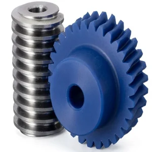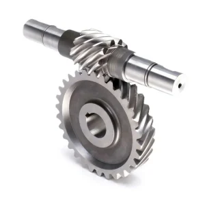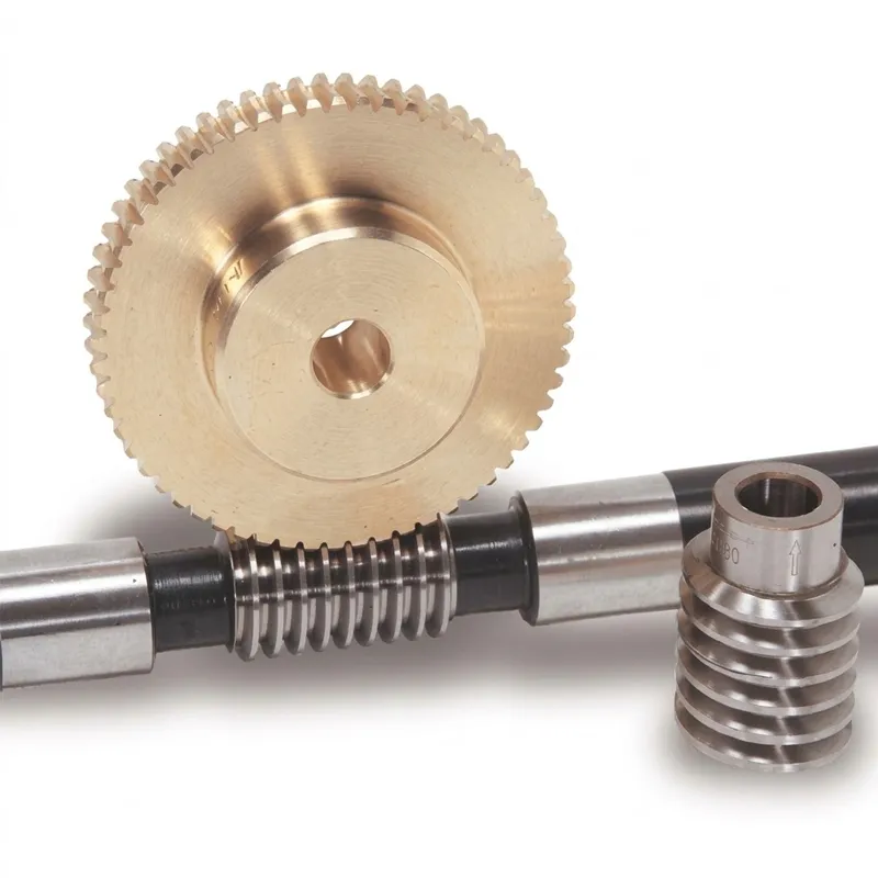
Engrenages à vis sans fin EP-Duplex
The EP-Duplex Worm Gear series is engineered for high-precision transmission systems requiring adjustable backlash and zero-clearance operation. Featuring a unique dual-lead design, these gears allow for precise center distance adjustment via axial shifting of the conical worm or rotation of an eccentric hub. Assembly is simplified with stamped orientation arrows on both the worm and wheel to ensure correct alignment, while a reference V-groove (60°, 0.3mm deep) on the tooth tip facilitates accurate positioning for near-zero backlash (±0.045). Available in configurations like the split-worm (System Ott) or split-wheel designs, they offer superior load capacity and rigidity. Ideal for CNC machines, rotary tables, and precision instruments, EP-Duplex Worm Gears ensure smooth, backlash-free performance in demanding applications.
PRECISION BACKLASH-ELIMINATING DRIVE COMPONENTS — WORM GEAR SERIES
Engrenages à vis sans fin EP-Duplex
Une ingénierie de précision duplex worm gear system — tapered worm thread geometry enabling near-zero backlash adjustment (±0.045 mm) through axial or rotational positioning, designed for CNC machine tool tables, precision indexing systems, metrological equipment, and any application where backlash elimination in a worm drive is a primary specification.
Technical Specifications — EP-Duplex Worm Gear Series
Core parameter reference. Custom worm hand, module, wheel tooth count, housing bore, and adjustment method available through our OEM programme.
| Paramètre | EP Series Value | Notes |
|---|---|---|
| Product Type | Duplex Worm Gear Set (conical worm) | Backlash-adjustable worm drive |
| Worm Type | Conical (tapered) duplex worm | Thread thickness varies axially |
| Backlash Specification | ±0.045 mm (near-zero) | At reference tooth / nominal center distance "a" |
| Adjustment Methods | Eccentric hub / Axial shift / System Ott / Dual disk wheel | Four options per housing design |
| Reference Tooth Marking | V-groove (60°, 0.3 mm deep) on tip peripheral | Identifies zero-backlash reference position |
| Assembly Orientation | Arrow stamped on worm and worm wheel | Both arrows must point same direction (Fig. 3) |
| Matière vermifuge | Case-hardened steel (58–62 HRC, ground) | Ra ≤ 0.4 μm thread surface |
| Matériau de roue à vis sans fin | Phosphor bronze (CuSn10P) / Nylon / POM (option) | Per application load and duty cycle |
| Worm Hand | Right-hand (RH) standard; LH on request | Both drive directions supported |
| Zero-Adjustment Mark | Marking groove (Markierungsrille) on worm shaft | Aligns with null-backlash center distance |
| Autobloquant | Yes, at low lead angles | Lead angle dependent |
| Certification de qualité | ISO 9001:2015 | Factory-wide QMS |
What Is a Duplex Worm Gear?
UN duplex worm gear is a specialised worm gear configuration designed specifically to eliminate — or reduce to a controllable minimum — the backlash that is inherent in conventional cylindrical worm drives. In a standard worm gear set, tooth-flank clearance is necessary to prevent tooth jamming due to manufacturing tolerances and thermal expansion, but this clearance appears as positioning deadband or lost motion in the output shaft. For CNC machine tables, telescope drives, metrological instruments, and precision actuators, this lost motion is directly equivalent to positioning error and is therefore unacceptable. The duplex worm gear solves this problem by using a conical (tapered) worm whose thread thickness varies along its length, so that axial displacement of the worm shaft moves the tooth contact point into a tighter mesh region, progressively removing the backlash without requiring component replacement.
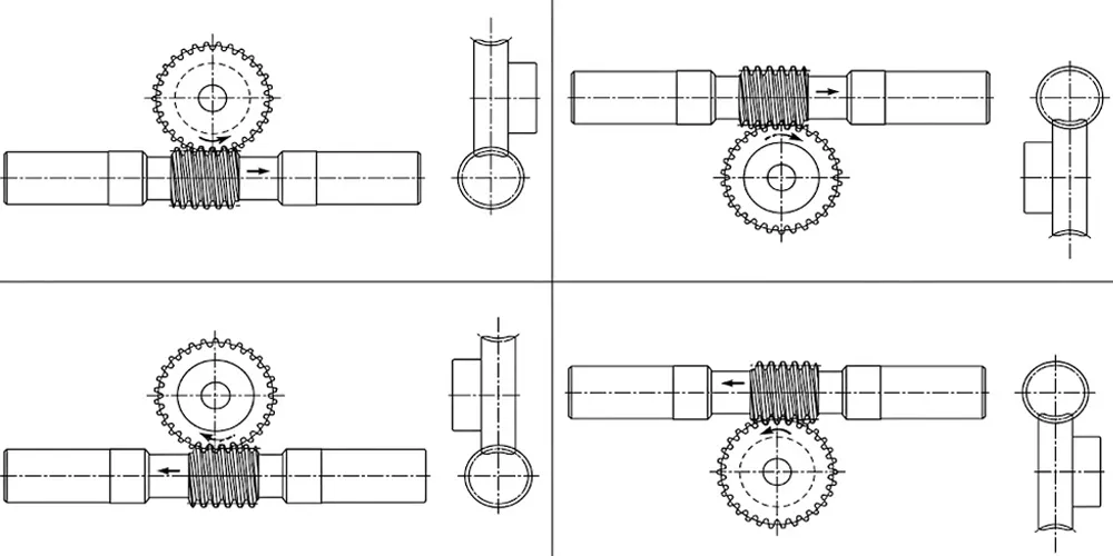
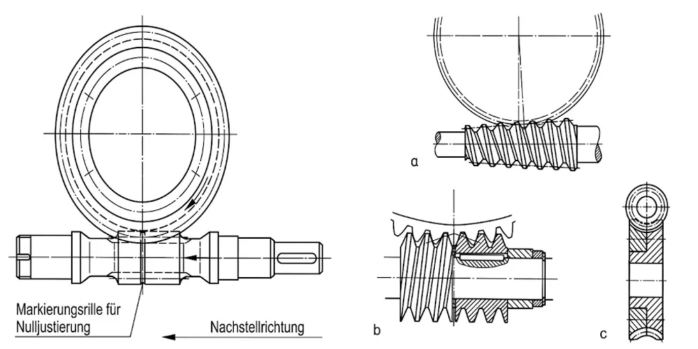
La série EP duplex worm gear draws on four established backlash adjustment methods documented in precision engineering practice. The first adjusts center distance by rotating an eccentric hub that cradles both the worm shaft and the worm gear wheel — a compact, non-invasive method suitable for sealed gearbox housings. The second uses axial shifting of a conical worm (Fig. 2a): as the worm moves axially, the varying thread thickness brings the flanks into tighter engagement with the wheel. The third divides the worm into two halves (Fig. 2b, System Ott): the two half-worms are rotated or axially displaced relative to each other so that one flank of each half contacts opposite tooth flanks of the wheel simultaneously, eliminating all clearance. The fourth divides the worm wheel into two disks (Fig. 2c) that are turned close to each other so that their combined tooth flanks grip the worm thread from both sides.
Each of these methods achieves the same engineering objective — near-zero backlash — through different physical mechanisms, giving the machine designer flexibility to select the approach that best fits the housing geometry, adjustment frequency, and assembly tooling available in their production environment.
Five Engineering Advantages of the Duplex Worm Gear System
① Near-Zero Backlash — Adjustable to ±0.045 mm
The defining technical property of the duplex worm gear is its adjustable near-zero backlash specification. When the reference tooth of the conical worm is aligned with the worm wheel center of rotation and the center distance is set to the designated value "a," the gear set delivers a backlash of approximately ±0.045 mm — achievable in production assembly without component lapping, selective fitting, or post-assembly rework. This specification positions the duplex worm gear as the standard choice for CNC rotary tables, precision dividing heads, and indexing fixtures used in machine tool and metrology applications across Germany, Japan, and North America where positioning repeatability under 0.05 mm is a baseline production requirement.
② Field-Adjustable Without Component Replacement
Unlike zero-backlash approaches requiring matched pairs or lapping, the duplex worm gear maintains its low-backlash specification through simple mechanical adjustment. As tooth wear gradually increases backlash over service life, the operator restores the original specification by shifting the worm axially or rotating the eccentric hub — adjustments performable in the field with standard tooling, often without removing the gearbox from the machine. This field-adjustability substantially lowers lifetime maintenance cost compared to alternatives requiring complete gear set replacement when backlash exceeds the acceptable limit.
③ Multiple Adjustment Methods — Design Flexibility
The four documented adjustment configurations — eccentric hub center distance variation, conical worm axial shift, System Ott dual half-worm, and dual disk worm wheel — give the machine designer genuine flexibility in how the backlash adjustment mechanism integrates into the housing and drive train. The conical worm axial shift method suits sealed gearboxes accessible only from the shaft end; the dual disk wheel method suits configurations where the worm shaft position is fixed and adjustment must come from the wheel side. No single universal duplex worm gear configuration fits all installation geometries, which is why the EP series covers all four.
④ Arrow-Mark Assembly System — Error-Proof Installation
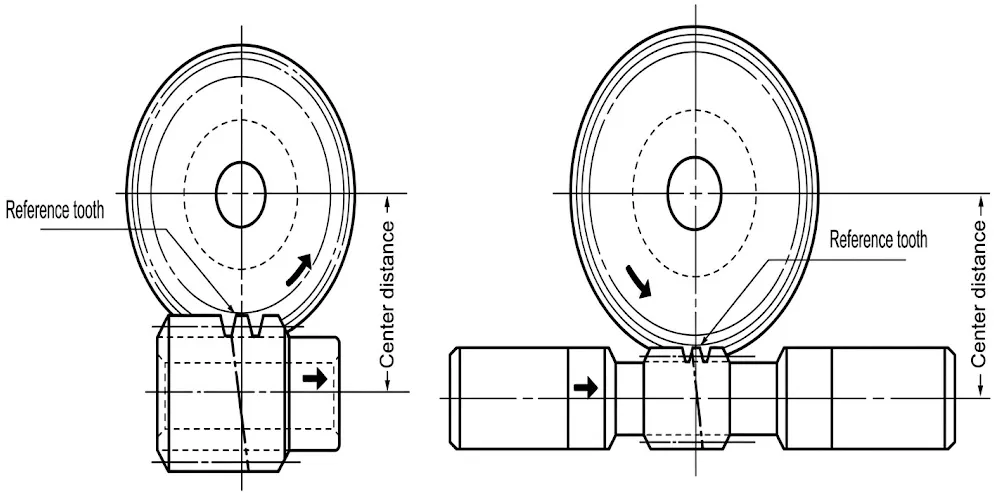
Correct assembly orientation is critical in a duplex worm gear set because the tapered thread means only one axial position produces the minimum-backlash condition. An orientation arrow is stamped on both the duplex worm and the worm wheel. When assembling, the operator aligns the arrow on the worm wheel front face with the arrow direction on the worm shaft — both arrows must point in the same direction (Fig. 3). If orientation is incorrect, the center distance "a" deviates from the average value, making the gear group difficult to mesh and preventing proper tooth engagement. This built-in verification system prevents costly assembly errors without requiring specialist setup equipment.
⑤ Reference Tooth V-Groove — Repeatable Zero-Backlash Positioning
The reference tooth of the duplex worm gear is marked with a V-groove (60°, 0.3 mm deep) on the tip peripheral of the tooth. This groove designates the reference tooth whose position, when aligned with the worm wheel center of rotation and the center distance set at value "a," produces the near-zero backlash condition (±0.045 mm). The V-groove allows rapid, unambiguous identification of the reference tooth during assembly or readjustment — an important time-saving feature when the gear set must be dismantled for maintenance and reassembled to specification, particularly for equipment in metrology laboratories in the UK, South Korea, and Australia.
How a Duplex Worm Gear Eliminates Backlash — The Four Methods
The fundamental question in understanding the duplex worm gear is how the duplex configuration extends the purpose of a standard worm drive. A standard worm gear transmits torque between 90°-crossed shafts at high reduction ratios, with inherent backlash from the tooth flank clearance. The duplex worm gear addresses this by cutting the worm with a conical (tapered) thread rather than a cylindrical one: thread thickness increases along the worm's length, so advancing the worm axially tightens the contact and removes flank clearance.
Method 1 — Eccentric Hub Center Distance Variation (Fig. 1)
The worm shaft and worm gear wheel are cradled in an eccentric hub. Rotating the hub changes the center distance between the two gear axes, moving the worm thread into tighter engagement with the wheel tooth flanks. A zero-adjustment marking groove (Markierungsrille für Nulljustierung) on the worm shaft and an adjustment direction indicator (Nachstellrichtung) guide the operator to the correct null-backlash center distance without measurement instruments. This method suits sealed gearbox housings where the eccentric hub is accessible from outside by rotating a single adjustment element.
Method 2 — Axial Shift of Conical Worm (Fig. 2a)
The worm is ground with a controlled conical taper along its length. Moving the worm axially within its bearing housing shifts the contact zone along the tapered thread flanks, bringing thicker thread sections into engagement with the wheel teeth and reducing tooth flank clearance. A single axial adjustment screw controls the worm position, and the backlash can be set to any value between the full-loose and full-tight positions. It is the preferred method in standard industrial duplex worm gear reducers where worm shaft accessibility is guaranteed by the gearbox design.
Method 3 — System Ott: Division of Worm in Two Halves (Fig. 2b)
The worm is divided into two axial halves. The two half-worms are rotated or shifted relative to each other on a common shaft — one half-worm contacts the left flank of each wheel tooth, the other contacts the right flank simultaneously, eliminating all clearance on both flanks at once. System Ott is the highest-precision variant of the duplex worm gear family, specified in telescope mounts and scientific instrument drives where any positional uncertainty is unacceptable.
Method 4 — Division of Wheel into Two Disks (Fig. 2c)
The worm wheel is split into two axial disks on the same hub. The two disks are rotated slightly relative to each other so their tooth flanks grip the worm thread from both sides simultaneously. This adjustment comes from the wheel side of the drive, making it suitable for configurations where the worm shaft position is fixed — for example a motor-integrated worm shaft that cannot be shifted axially. Turning the two disks close together until flank contact is achieved on both sides removes backlash without modifying the worm or its bearings.
A practical question when specifying a duplex worm gear is: can a worm gear go both directions? Yes — worm gears drive in either rotational direction depending on the worm thread hand (RH or LH) and motor direction. The duplex adjustment mechanism is direction-neutral and eliminates backlash equally in both drive directions, making the duplex worm gear ideal for bidirectional servo-driven precision positioning axes.
Assembly Verification — Orientation Arrows and Reference Tooth
Correct assembly of a duplex worm gear set is more critical than for a standard cylindrical worm drive, because the conical geometry means that only a specific rotational orientation of the worm relative to the wheel produces the intended backlash value. Two verification steps must be followed in sequence during initial installation and any subsequent reassembly after maintenance.
Step 1 — Verifying Assembly Orientation (Fig. 3)
An orientation arrow is stamped on the front face of both the duplex worm and the worm wheel. During assembly, the worm wheel is positioned so that its arrow mark on the front face aligns directionally with the arrow on the worm shaft — both arrows must point in the same direction. If the orientation is reversed, the center distance "a" will deviate above the average value, causing difficulty in gear engagement and preventing the tooth flanks from seating correctly. The arrow-mark system prevents assembly error without any measurement instruments or setup gauges.
Step 2 — Verifying Reference Position (Fig. 4)
A V-groove (60°, 0.3 mm deep) is cut into the tip peripheral of the reference tooth on the duplex worm gear. This groove identifies the one tooth whose position, when aligned with the center of rotation of the worm wheel with the center distance set to the specified value "a," produces a backlash of approximately ±0.045 mm. The V-groove is visible to the naked eye and allows rapid identification without magnification, enabling service technicians to re-establish the zero-backlash position quickly during field maintenance — the final check before the gearbox is closed and returned to service.
Material Specification — Precision Gear Materials for Duplex Worm Drives
Material selection for a duplex worm gear is stricter than for a standard worm gear, because the near-zero backlash specification depends on the dimensional stability of both worm and wheel tooth flanks over service life. Wear at the flank surfaces directly translates to increased backlash, defeating the purpose of the duplex configuration. What is the best plastic material for gears in lower-load duplex worm applications? For precision drives, the material hierarchy runs from phosphor bronze (highest load, best dimensional stability) through nylon worm gear variants down to plastic worm wheel configurations for the lightest precision instrument applications.
Worm (Screw) — Case-Hardened Steel, Ground
The conical duplex worm is manufactured from case-hardened steel — typically 20CrMnTi or equivalent — ground to the required conical thread profile after hardening. Case hardening produces a hard surface layer (58–62 HRC) over a tough core, giving the worm thread wear resistance to maintain dimensional integrity over the high sliding-contact duty of a worm mesh. The precision ground finish achieves Ra ≤ 0.4 μm required for the near-zero backlash condition to be reproducible across assembled gear sets without selective fitting.
Worm Wheel — Phosphor Bronze
The worm wheel is hobbed from phosphor bronze (CuSn10P or equivalent), which provides low friction against hardened steel, adequate compressive strength (yield strength approximately 200 MPa), and good conformability at the mesh interface. Phosphor bronze's lower hardness allows the wheel tooth to conform under initial running-in loads — bringing the contact patch to its full design area — while remaining dimensionally stable under sustained rated load. Bronze worm wheel production for precision drives is the established material standard globally for the duplex worm gear worm wheel.
Polymer Option — Nylon and POM for Lightweight Variants
For lighter-duty precision applications — scientific instrument drives, optical positioners — a nylon worm gear or plastic worm wheel variant can be specified. A nylon worm wheel against a hardened steel conical worm provides adequate wear resistance for intermittent, low-load duty while offering lubricant-free operation and lower weight. POM (Polyacetal) offers better dimensional stability than nylon in small-bore configurations, making it the preferred plastic worm drive wheel material where bore tolerance maintenance is critical across the temperature range. All material grades are processed under our ISO 9001:2015 certified QMS.
Application Scenarios — Where Duplex Worm Gears Are Specified
Le duplex worm gear is not a general-purpose drive component. Its engineering justification is specific: applications where the backlash of a standard worm gear is the binding constraint on system performance and where periodic re-adjustment over service life is preferable to component replacement.
CNC Machine Tool Rotary Tables
CNC machining centre rotary tables and 4th/5th axis units require positioning accuracy below 0.05° and backlash well below 0.1 mm to meet dimensional tolerances of aerospace and automotive precision machining. The duplex worm gear with eccentric hub adjustment or conical worm axial shift is the standard drive configuration for these tables — used in machine tool factories across Germany, Japan, South Korea, and Canada where tight angular positioning is a production baseline requirement.
Precision Indexing and Dividing Heads
Indexing fixtures, dividing heads, and precision rotary positioners used in gear manufacturing, gear inspection, and multi-axis measurement systems specify the duplex worm gear for its ability to maintain angular positioning repeatability over tens of thousands of indexing cycles. The field-adjustable backlash specification means the dividing head can be returned to original accuracy after extended service without a workshop overhaul — a practical benefit for production environments in the UK, Australia, and Southeast Asia.
Telescope and Astronomical Instrument Drives
Telescope equatorial mount drives and observatory tracking systems use System Ott dual half-worm duplex worm gear configurations to achieve near-zero positional uncertainty needed for long-exposure astrophotography. A standard worm gear with 0.1 mm backlash would produce visible star trailing in long exposures. System Ott eliminates this, and the adjustment mechanism allows field recalibration when temperature changes affect center distance — a real operational requirement for outdoor observatory equipment in variable-climate locations.
Coordinate Measuring Machines (CMM)
CMM rotary axes require the drive stage to introduce zero lost motion into the measurement loop. The duplex worm gear with dual disk wheel adjustment is used in CMM rotary positioning stages where the worm shaft is motor-mounted and adjustment must come from the wheel side. The V-groove reference tooth system allows calibration traceability to be maintained across service intervals — an important requirement for metrology equipment in ISO/IEC 17025 accredited laboratories.
Radar Antenna and Satellite Positioners
Military and civil radar antenna drives and satellite dish positioners use duplex worm gear drives for high reduction ratio, self-locking position hold, and adjustable near-zero backlash that prevents antenna hunting in closed-loop control systems. The field-adjustable design is particularly valuable for remote antenna installations in Canada, Australia, and the Middle East where full gearbox replacement represents a major logistics cost.
Medical Imaging and Radiotherapy Equipment
Radiotherapy gantry rotation drives and medical imaging positioning systems use precision duplex worm gear stages because positioning error translates directly to clinical risk. The ±0.045 mm backlash specification backed by ISO 9001:2015 certified production documentation satisfies the dimensional accuracy requirements of medical device drive systems regulated under IEC 60601 and FDA 21 CFR Part 820 frameworks across global markets.
Related Products — One-Source Drive System Supply
Beyond the EP duplex worm gear series, we manufacture complementary drive components that complete a full precision drive train specification — all traceable to the same ISO 9001:2015 certified quality system.
Engrenage à double hélice
In multi-stage drive trains where a duplex worm gear stage handles the final right-angle high-ratio reduction, a double helical gear stage is often used upstream to handle the first speed reduction from the prime mover at higher efficiency. The opposing helix angles of the double helical gear cancel axial thrust, keeping upstream shaft bearings simple while delivering load capacity at the motor-adjacent stage. Our double helical gear series is dimensionally compatible with the EP drive system portfolio, supporting single-supplier procurement for the complete drive chain.

Porte-bagages
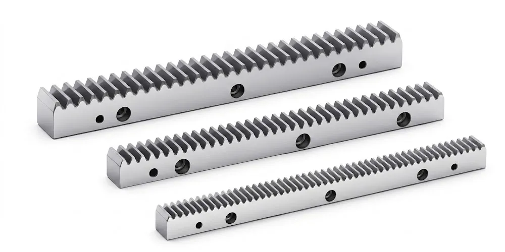
Where the rotary output of a duplex worm gear reduction stage drives a linear axis — as in a CNC table linear feed axis or gantry system — our gear rack series provides the matching pinion-to-rack interface at the output. Metric module racks in steel, stainless steel, and engineering polymer grades are available across module sizes compatible with the pinion spur gear driven by the worm wheel output shaft. Single-supplier sourcing of both the precision worm stage and the linear output stage simplifies qualification documentation and incoming inspection management for precision machine builders.
Order and Trade Information
Minimum Order Quantity
Standard duplex worm gear sets carry a baseline MOQ. Mixed configurations — different adjustment methods, worm hands, or wheel tooth counts — can be combined into a single order totalling approximately USD 1,500. For engineering evaluation and first-article qualification, 1–5 pcs samples are available at sample pricing. Very small orders of 1–2 pcs for prototype or spare requirements can be assessed individually, with per-unit cost higher at sub-baseline quantities.
Lead Time
Standard catalogued duplex worm gear configurations: 10–25 working days. High-precision ground worm variants or custom center distance specifications: 30–60 working days. Custom OEM configurations from customer drawing: 20–45 working days. Sample and first-article orders (1–5 pcs): 7–25 working days, with complex or high-precision configurations assessed individually before lead time confirmation.
Incoterms and Payment
Standard component orders: EXW, FOB, CIF, and DAP available. Samples and urgent spare parts: EXW / FCA / DAP / courier service. FCA, CFR, CPT, CIP, and DDP negotiable for established procurement programmes. Payment: T/T and L/C both accepted. Packing: precision gear sets individually protected in cartons with cushioning; wooden packing available for bulk orders.
OEM / Custom Programme
Full OEM and custom duplex worm gear production from customer engineering drawings or physical samples. MOQ for custom configurations depends on module, material, precision class, and adjustment mechanism. Drawing approval precedes production release. Full dimensional and material certification documentation, including worm conicity parameter verification, is provided at delivery for every custom batch to support machine tool and medical device OEM qualification requirements.
About Our Precision Drive Manufacturing Capability
With over ten years of specialised expertise in precision mechanical power transmission, our facility produces a full range of industrial drive components under a single ISO 9001:2015 certified quality management framework. Our manufacturing portfolio spans agricultural gearboxes, worm gear reducers, planetary drive systems, power take-off shafts, hydraulic cylinders, drive chains, gears of all types, and industrial motors — each designed and built in-house with traceable dimensional documentation.
On the structural side we produce gearbox housings and assemblies in ductile iron, grey cast iron, cast steel, precision cast steel, and cast aluminium. Our component range includes gears, sprockets, worm gears, pulleys, shafts, and worms in standard and non-standard configurations. For the EP duplex worm gear series, we operate CNC worm grinding equipment capable of the precision ground thread surface (Ra ≤ 0.4 μm) required for the ±0.045 mm backlash specification, with conical worm geometry verified by dimensional inspection documented in the delivery certification package.
Direct factory supply — no intermediary trading layer — keeps procurement lead times competitive and documentation packages complete for customers qualifying our products into regulated supply chains in Germany, Japan, South Korea, Canada, Australia, and the UK.
Atelier




Foire aux questions
Éditeur : PXY