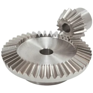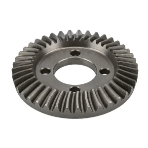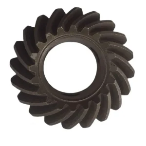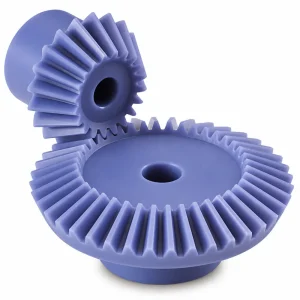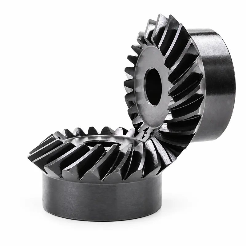
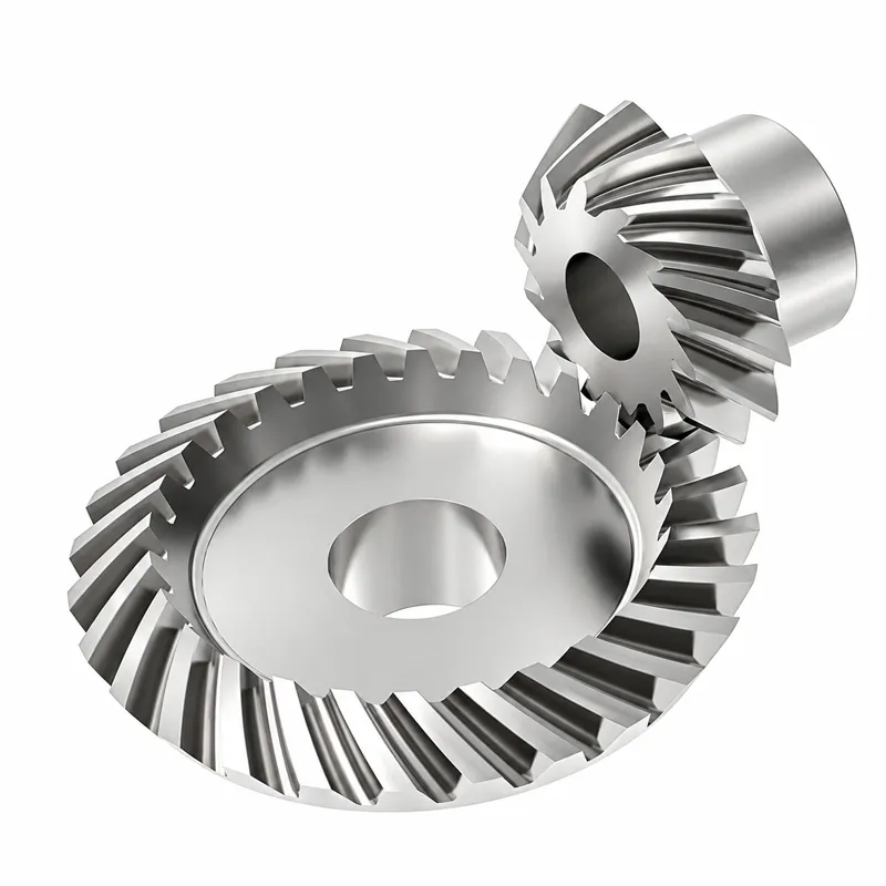
EP-Spiral Bevel Gear
The EP-Spiral Bevel Gear series delivers high-precision power transmission for demanding applications in automatic control machines, semiconductor equipment, medical devices, solar energy systems, and machine tools. Available in standard modules including M3, M4, M5, M8, and M12, these gears are manufactured from versatile materials such as Brass, C45 Steel, Stainless Steel, Copper, POM, Aluminum, and Alloy. To ensure superior durability and smooth operation, teeth undergo hardening, milling, or grinding processes, achieving precision grades of DIN6 to DIN9 with tight tolerances ranging from 0.001mm to 0.1mm. Comprehensive surface treatments—including Zinc/Nickel plating, Passivation, Oxidation, Anodizing, Geomet, Dacromet, Black Oxide, Phosphatizing, Powder Coating, and Electrophoresis—provide excellent corrosion resistance.
EP-Spiral Bevel Gear — Precision Curved-Tooth Angular Drive Components for High-Speed, Low-Noise Transmission
The EP-Spiral Bevel Gear is a technically advanced angular power transmission component engineered for applications where smooth engagement, reduced noise, and sustained load capacity must coexist within a compact gear envelope. Unlike straight-tooth bevel gears that produce sudden impact at tooth entry, the spiral bevel gear's curved tooth geometry ensures progressive, multi-tooth contact throughout each mesh cycle — distributing load across a greater contact area, lowering transmission error, and dramatically reducing the vibration signature of the drive. Available in module sizes M3, M4, M5, M8, M12 and additional configurations, with materials spanning Brass, C45 steel, Stainless steel, Copper, POM, Aluminum, and Alloy grades, this series addresses the full spectrum of industrial demands from semiconductor handling equipment in South Korea and Japan to machine tool spindle drives in Germany, solar tracking systems in Australia, and medical device actuators in the United States and Canada. Each spiral bevel gear is manufactured to DIN6 through DIN9 precision grades, with tooth treatments including hardening, milling, and precision grinding — supported by ISO, DIN, ANSI, JIS, and BS standards compliance across the entire product family.
Technical Specifications — EP-Spiral Bevel Gear
The table below consolidates the full technical specification for the EP-Spiral Bevel Gear series. All parameters are verified production standards, not nominal estimates. Engineers specifying a spiral bevel gear for a new application should use the module range, precision grade, and tooth treatment data below as the primary baseline for gear mesh calculations and housing design review.
| EP-Spiral Bevel Gear — Complete Technical Specification | |
|---|---|
| Parametr | Value / Detail |
| Model Number | M3, M4, M5, M8, M12 and etc. |
| Tworzywo | Brass, C45 steel, Stainless steel, Copper, POM, Aluminum, Alloy, and so on |
| Obróbka powierzchni | Zinc-plated, Nickel plated, Passivation, Oxidation, Anodization, Geomet, Dacromet, Black Oxide, Phosphatizing, Powder Coating, Electrophoresis |
| Standard | ISO, DIN, ANSI, JIS, BS, and Non-standard |
| Precision Grade | DIN6, DIN7, DIN8, DIN9 |
| Teeth Treatment | Hardened, Milled, or Ground |
| Tolerance | 0.001 mm – 0.01 mm – 0.1 mm |
| Finish | Shot/sandblast, heat treatment, annealing, tempering, polishing, anodizing, zinc-plated |
| Items Packing | Plastic bag + Cartons or Wooden Packing |
| Payment Terms | T/T, L/C |
| Production Lead Time | 20 business days for sample; 25 business days for bulk |
| Samples | Available; express shipping cost covered by client |
| Aplikacja | Automatic controlling machinery, semiconductor industry, general industry machinery, medical equipment, solar energy equipment, machine tool |
The bevel gear pressure angle for the EP-Spiral series is standardised at 20° across all module sizes, consistent with ISO and DIN reference geometry. Custom pressure angle configurations between 14.5° and 25° are available under the non-standard programme, allowing tooth strength and contact ratio to be optimised for specific pitch line velocity and torque load combinations — a service frequently requested by spiral bevel gear manufacturers' customers in the machine tool and precision automation sectors.
How Does a Spiral Bevel Gear Work — The Engineering Behind Curved-Tooth Angular Drive
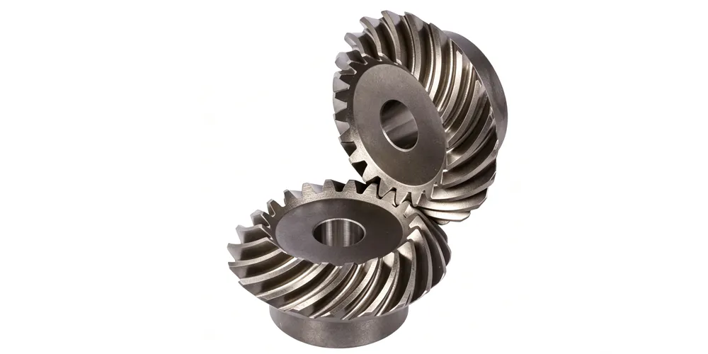
A spiral bevel gear operates on the same conical pitch surface principle as any bevel gear, but its defining characteristic is the spiral angle in bevel gear geometry — the angle at which the tooth trace crosses the pitch cone element. In a spiral bevel gear, this angle typically falls between 25° and 45°, creating a curved tooth profile that wraps partially around the cone face. As the gear rotates, each tooth enters mesh progressively from the toe toward the heel rather than engaging the full face width simultaneously. This gradual engagement profile is the root cause of the spiral bevel gear's superior performance in high-speed, noise-sensitive applications: contact ratio is higher than a straight bevel counterpart, the effective load per unit tooth width is lower, and the transition force through each mesh cycle is far smoother.
The mechanical result of this geometry is that a spiral bevel gear can carry significantly more torque relative to its size compared to a straight bevel gear of identical module and face width, because load is shared across multiple teeth simultaneously. This is one of the primary bevel gear advantages that makes the spiral form the dominant choice in high-performance gearboxes — automotive differentials, right angle spiral bevel gearbox assemblies for industrial machinery, and helicopter main rotor transmission stages all exploit this property. The spiral bevel gear set's directional characteristics are worth noting: unlike hypoid spiral bevel gears (where shaft axes are offset), a true spiral bevel gear set has intersecting axes, meaning no sliding along the tooth face in the lengthwise direction and therefore better mechanical efficiency than a hypoid arrangement when both are operating at comparable pitch line velocities. For engineers comparing bevel gear vs spur gear performance, the spiral bevel gear occupies a distinct position: it transmits power between non-parallel, intersecting shafts — something no spur or helical parallel-shaft gear can achieve — while matching or exceeding the noise performance of a high-quality helical gear stage.
The gear ratio of bevel gear pairs in the EP-Spiral series follows straightforward tooth count arithmetic, identical to other bevel types: ratio equals the driven gear's tooth count divided by the driving pinion's tooth count. What distinguishes the spiral form is the ability to achieve this ratio at substantially higher pitch line velocities — routinely 35 m/s in ground-tooth configurations and beyond in aerospace-grade applications — without the noise and dynamic load penalties that limit straight bevel gears to lower speed duties. This makes the spiral bevel gear the natural selection when the drive ratio requirement and the speed requirement must both be satisfied within the same gear mesh.
Five Key Advantages of the EP-Spiral Bevel Gear
① Progressive Multi-Tooth Engagement
The curved tooth trace of a spiral bevel gear ensures that at least two teeth are in contact simultaneously throughout the mesh cycle, raising the contact ratio above 1.5 in well-designed spiral bevel gear sets. This continuous load sharing reduces peak Hertzian contact stress per tooth, extends fatigue life, and eliminates the impact noise associated with single-tooth entry — the defining acoustic and reliability advantage over straight bevel designs that makes the spiral form standard in all high-cycle industrial and automotive precision bevel gear applications.
② Wide Module Range — M3 to M12+
With available module sizes including M3, M4, M5, M8, and M12 (plus additional configurations on request), the EP-Spiral Bevel Gear covers a broad torque envelope within a single product family. Smaller modules suit precision instrument drives and semiconductor handling equipment, while larger modules handle the structural demands of machine tool head drives and general industry gearboxes. This span eliminates the need to qualify multiple gear suppliers across a product line.
③ DIN6–DIN9 Accuracy with Ground Tooth Finish
Precision grades DIN6, DIN7, DIN8, and DIN9 are standard, with tooth finish options of hardened, milled, or ground surfaces. Spiral bevel gear grinding to DIN6 achieves sub-micron pitch error, enabling operation at pitch line velocities beyond 25 m/s without tonal noise. Dimensional tolerances from 0.001 mm to 0.1 mm are selectable based on application duty, giving design engineers precise control over backlash, thermal expansion allowances, and preload margins within the assembled gearbox housing.
④ Comprehensive Surface Treatment Options
Eleven surface treatment processes are available: Zinc-plating, Nickel plating, Passivation, Oxidation, Anodization, Geomet, Dacromet, Black Oxide, Phosphatizing, Powder Coating, and Electrophoresis. This catalogue of surface options allows the spiral bevel gear to be tailored for specific corrosion environments — Geomet and Dacromet for outdoor machinery in humid climates, Nickel plating for chemical-exposure environments, Black Oxide for machine tool applications where residual oil film corrosion protection is standard practice in European manufacturing facilities.
⑤ Flexible Lead Times and Multi-Standard Compliance
Sample production in 20 business days and bulk delivery in 25 business days, with T/T and L/C payment terms, supports both prototype validation and serial production scheduling globally. Compliance with ISO, DIN, ANSI, JIS, and BS standards means a single spiral bevel gear design can be certified for use across European, North American, and Asian market standards without re-engineering — a significant advantage for OEM customers building globally distributed product lines
Material Engineering for the EP-Spiral Bevel Gear Series
Material selection for a spiral bevel gear is a multi-variable decision that balances tooth contact fatigue life, bending strength, surface finish capability, weight, and environmental resistance. The EP-Spiral series addresses this by offering seven primary material families, each matched to a distinct category of duty and environment.
C45 steel is the workhorse grade across the industrial segment. With through-hardening capability to approximately 50 HRC and excellent machinability, C45 allows spiral bevel gear cutting on milling machine and hobbing centres to achieve DIN7 or DIN8 grade accuracy cost-effectively for general industry machinery and machine tool head drives. Where higher contact fatigue resistance is required — gearboxes operating at the upper end of the M12 module range or under high-frequency load cycling — alloy steel grades (20CrMnTi, 42CrMo4) are specified, enabling case-hardening depths of 0.8–1.5 mm with surface hardness of 58–62 HRC and retained toughness in the core. Stainless steel spiral bevel gears resist chemical attack and humid environments, making them the standard choice for solar energy tracking drive units exposed to outdoor weathering in Australia and the Netherlands, and for food and pharmaceutical conveyor right angle drives in Canada and the United Kingdom. Brass and copper offer outstanding machinability, natural corrosion resistance, and low friction against steel counter-gears, positioning them as the natural choice for instrument and timing drives where smooth operation and long lubrication intervals matter more than ultimate load capacity. POM (acetal polymer) brings the benefits of low running noise and zero-lubrication capability to medical equipment drives and semiconductor wafer handling equipment in South Korea and Japan — environments where oil contamination is simply not acceptable. Aluminum alloy spiral bevel gears reduce rotating inertia for rapid-cycle automation applications and weight-sensitive portable equipment designs in which mass reduction delivers measurable energy efficiency benefits across long production runs.
Installation Guidance — How to Install a Spiral Bevel Gear Correctly
Correct installation of a spiral bevel gear is more demanding than fitting a parallel-shaft gear stage because the conical geometry introduces both radial and axial force components at the mesh, and these must be balanced precisely through bearing selection, shaft positioning, and preload adjustment. Understanding how to install a precision bevel gear of the spiral type starts with recognising that mounting distance — the axial position of each gear's pitch apex relative to the intersection point of the two shaft axes — is the most critical assembly dimension.
The installation sequence for a spiral bevel gear set in a right angle spiral bevel gearbox follows these principal steps. First, mount the pinion shaft assembly in its bearings and set pinion preload through a collapsible spacer or shimmed solid spacer arrangement, targeting a rolling drag torque of 1.0–2.0 N·m at the pinion shaft. Record the achieved preload before introducing the ring gear. Second, position the ring gear carrier to achieve the specified backlash — for the EP-Spiral series, standard backlash for M5 gears is in the range of 0.10–0.20 mm measured at the ring gear rim perpendicular to the tooth face. Backlash is set by adjusting ring gear carrier shims or threaded adjustment rings. Third, verify tooth contact pattern using engineer's blue or gear marking compound on six to eight ring gear teeth. A correct spiral bevel gear contact pattern under light load appears centred lengthwise on the tooth face, covering 50–65% of the face length, and positioned toward the midpoint of the tooth height. Avoid patterns that concentrate entirely at the toe or heel under no-load conditions — these shift to destructive edge contact under full torque. Fourth, torque all housing fasteners to specification and recheck backlash after torquing, as housing distortion can alter the assembled backlash by 0.01–0.03 mm. This sequence holds whether the gearbox housing is cast iron, cast aluminum, or precision cast steel, and regardless of whether the spiral bevel gear set is a standard ratio or a non-standard ODM configuration.
Spiral Bevel Gear Application Scenarios — Where Curved-Tooth Performance Delivers
The precision bevel gear application landscape for the EP-Spiral series covers six distinct sectors, each exploiting a different aspect of the spiral tooth geometry's performance envelope. The following application cards outline the primary use cases and the specific spiral bevel gear characteristics that make this product the correct technical choice in each context.
⚙ Automatic Controlling Machinery
Robotic arm wrist joints, CNC tool changers, and automated guided vehicle steering modules all require a spiral bevel gear that delivers angular redirection of motor torque within tight packaging constraints while maintaining positional repeatability over millions of cycles. The progressive contact ratio of the spiral bevel gear eliminates the dwell-and-impact cycle of straight bevel engagement, protecting servo encoder feedback from vibration-induced position errors in high-cycle automation applications across factories in Germany, Japan, and South Korea.
💡 Semiconductor Industry Equipment
Wafer handling robots, lithography stage drives, and pick-and-place systems in semiconductor fabs operate in cleanroom environments where particulate generation from gear wear is unacceptable. POM and stainless steel spiral bevel gear variants operating without lubrication eliminate oil mist contamination risk while delivering the precise angular positioning that sub-micron lithography stages demand. These specifications are standard in semiconductor equipment installed in facilities in South Korea, Japan, and Taiwan, where the EP-Spiral series' DIN6 accuracy grade satisfies the transmission error budgets typical of cleanroom automation design.
☀ Solar Energy Tracking Systems
Single-axis and dual-axis solar tracker drives use a right angle spiral bevel gearbox to convert motor rotation into the tilting motion of the panel array. The spiral bevel gear's continuous multi-tooth contact absorbs the dynamic shock loads generated when wind gusts act on large panel arrays — a load profile that causes rapid tooth wear in straight bevel alternatives. Stainless steel or Geomet-coated alloy steel versions of the EP-Spiral series are selected for solar farms in coastal and high-humidity regions in Australia and the Netherlands where long-term corrosion resistance directly determines system maintenance intervals.
🏥 Medical Equipment Drives
Surgical robot joints, diagnostic imaging gantry drives, and infusion pump mechanisms all depend on a precision bevel gear that generates minimal noise, sustains accurate angular positioning, and tolerates sterilisation procedures without dimensional change. POM and stainless spiral bevel gear configurations meet these requirements simultaneously — POM for noise and cleanliness in dispensing applications, stainless for autoclave resistance in surgical instruments. Medical equipment installed in hospitals across Canada, the United Kingdom, and the United States is a primary market for these specifications.
🔩 Machine Tool Head Drives
Milling machine spindle head drives, boring head angular drives, and grinding machine pivot axes have historically been among the most demanding spiral bevel gear applications because surface finish on the machined workpiece is directly sensitive to any periodic error in the gear drive. Spiral bevel gear grinding to DIN6 grade using the EP-Spiral series' ground tooth finish option achieves pitch errors below 3 µm on M5 gears, satisfying the transmission error budgets of high-precision machine tool builders in Germany and Japan where axis drive quality is a primary differentiator in the finished machine's specification sheet.
🏭 General Industrial Gearboxes
Right angle helical bevel gearboxes and standard right angle spiral bevel gearbox housings across conveyor systems, packaging machinery, and processing plant drives use spiral bevel gear sets at their core angular change-of-direction stage. The gear ratio of bevel gear pairs in these gearboxes typically ranges from 1:1 to 5:1, covering the majority of industrial drive ratio requirements when combined with a parallel helical pre-reduction stage. C45 steel at DIN8 accuracy is the standard industrial specification, with alloy steel upgrade available for heavy-duty cycling duties.
About Our Facility — Precision Gear Engineering Since Over a Decade
Our production facility brings more than ten years of accumulated expertise in mechanical power transmission to the manufacturing of the EP-Spiral Bevel Gear series and the broader range of drive components that surround it. The product range spans agricultural gearboxes, worm gear reducers, planetary drive assemblies, power take-off shafts, hydraulic cylinders, roller chains, sprockets, and industrial motors — a comprehensive catalogue built on the same ISO 9001:2015 quality management foundation that underpins every spiral bevel gear we ship.
We design and manufacture industrial and agricultural gearbox assemblies in ductile iron, cast iron, cast steel, precision cast steel, and cast aluminum, alongside standard and non-standard precision mechanical parts including gears, worm gears, worms, pulleys, and transmission shafts. This integration of gear machining and gearbox manufacturing under one roof means we understand both how a spiral bevel gear behaves as an isolated component and how it interacts with the housing, bearings, shafts, and seals that form the complete assembly. For spiral bevel gear customers in the machine tool, solar energy, semiconductor, and medical equipment sectors, this breadth provides a single point of technical accountability from tooth profile specification through to final assembly dimensional verification — a genuinely rare capability among spiral bevel gear manufacturers in the global industrial supply market.
Warsztat




Compatible Drive Components — Complete System from a Single Source
A spiral bevel gear rarely functions as a standalone unit. In the majority of industrial and automation gearbox architectures, it operates alongside helical parallel-shaft stages that handle primary speed reduction, and downstream linear drive elements that convert the rotary output into positional movement. Sourcing all of these components from the same precision gear manufacturing facility guarantees dimensional compatibility, matched accuracy grades, and consistent material and surface finish standards across the full drivetrain assembly.
Podwójne koło zębate śrubowe
In multi-stage helical bevel gearboxes and right angle helical bevel gearboxes, a double helical gear (herringbone) stage handles the primary torque multiplication step on the parallel input shaft, before the spiral bevel gear redirects the drive axis through 90°. The herringbone tooth geometry cancels axial thrust completely — an important feature when the downstream spiral bevel gear mesh is already generating combined radial and thrust loads on its own bearing set. Matching the double helical gear module and accuracy grade to the spiral bevel gear stage from the same source eliminates interface tolerance accumulation and simplifies assembly documentation across the gearbox design.

Listwa zębata
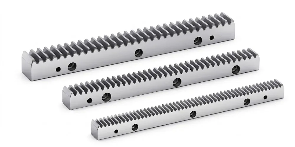
When the output shaft of a spiral bevel gearbox needs to drive a linear positioning system — a machine tool axis, a solar tracker's tilt mechanism, or an automated warehouse crane — a gear rack and mating pinion converts the rotary bevel gear output into controlled linear displacement. The accuracy grade of the gear rack must be matched to the spiral bevel gear stage upstream to prevent rack pitch error from becoming the limiting factor in the overall positional accuracy of the linear axis. We manufacture gear racks in the same facility using consistent material and finish standards, ensuring that the combined spiral bevel gear and gear rack system delivers the positional accuracy and surface life that the application demands.
Frequently Asked Questions — EP-Spiral Bevel Gear
Redaktor: PXY