
FIELD DIAGNOSTICS & FAILURE GUIDE
A structured breakdown of the mechanical, operational, and material factors behind in-season round baler PTO shaft failures — and how operators can detect the warning signs before a breakdown stops the harvest.
Mid-season failure of a round baler PTO shaft is one of the most disruptive events in a hay or forage operation. The breakdown typically happens at the worst possible moment — during the narrow weather window between cuttings, when every available hour of dry conditions is critical. Yet in most cases the failure was not sudden. The physical evidence almost always points to a fault that had been developing for days or even weeks: a U-joint that was already clicking at engagement, a slip clutch that had been releasing inconsistently, or a telescoping tube whose internal spline was corroded enough to bind at turning angles. Understanding the specific failure mechanisms behind a round baler PTO shaft breakdown helps operators recognise these early signals and act before a component gives out in the field.
This guide examines the principal causes of in-season driveshaft failure across the main baler platform categories — including John Deere, CASE IH, and Krone round balers — and covers the manufacturing factors, operational patterns, and maintenance gaps that combine to shorten driveline service life.
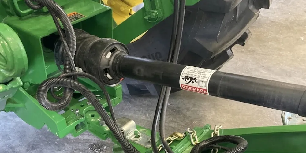
The Mechanics Behind Mid-Season Failure
A round baler PTO shaft does not fail the way a structural component fails under a single overload. Driveshaft failure is almost always a fatigue process — repeated stress cycles gradually degrade a component until it can no longer carry the peak loads it encounters during dense crop conditions. The universal joint cross is the most common failure point. Each rotation of the shaft puts the cross through two complete bending cycles at the operating articulation angle. At 1000 RPM over a ten-hour baling day, that amounts to over one million bending cycles per day of operation. When the bearing cups run dry due to missed lubrication intervals, the contact stress at the needle roller surfaces rises sharply, accelerating both wear and fatigue crack initiation at the cup shoulder — the weakest cross-section of the hardened steel cross body.
Telescoping tube failure is less common but more damaging when it occurs. If the inner and outer tube profiles are corroded or contaminated with crop material, the tubes bind at operating angles rather than sliding freely. The shaft then operates at an artificially elevated angle across the constant-velocity joint, increasing the cyclic velocity variation transmitted to the baler gearbox input shaft. Over time this repetitive angular loading damages the gearbox input bearing — a failure that is significantly more expensive to repair than the driveshaft itself. Operators who notice stiffness in the telescoping action early in the season and ignore it are typically the ones dealing with gearbox repairs before the second cut.
Root Cause Analysis: Common Failure Modes
| Failure Mode | Primary Cause | Early Warning Sign | Downstream Risk |
|---|---|---|---|
| U-joint cross fracture | Dry bearing cups, fatigue crack | Clicking at engagement, vibration | Yoke ear damage, full shaft replacement |
| Slip clutch glazing | Repeated overload above rated torque | Inconsistent release, slipping at normal load | Gearbox overload, disc replacement |
| Telescoping tube binding | Corrosion, crop ingestion, dry splines | Stiff manual extension, knocking sound | Elevated angle load on CV head, gearbox bearing wear |
| Guard tube failure | UV degradation, crop wrap impact | Cracks, missing end cones | Operator safety risk, crop fire hazard |
| Weld seam crack at yoke | Undersized shaft for actual torque load | Visible surface crack, vibration on acceleration | Sudden shaft separation under load |
| Lockback collar jamming | Corrosion, crop debris in collar groove | Difficult disengagement, collar sticking | Inability to detach shaft safely in the field |
Manufacturing Construction and Failure Susceptibility
The way a round baler PTO shaft is constructed directly determines how it responds to field conditions over a season. Shafts built to lower manufacturing tolerances — particularly at the U-joint bearing cup bore — develop play earlier because the needle rollers are not seated against a precision-ground surface. Once play develops, the cross rocks inside the yoke ear during each rotation cycle, applying an impact load against the cup shoulder rather than a pure rolling contact. This transitions the contact mode from fatigue-limited rolling to impact-fatigue, dramatically shortening the remaining service life of the joint.
The telescoping tube cross-section profile is another construction variable that affects failure risk. Star and lemon profiles, when machined to close tolerances, maintain low sliding friction throughout the operating range. Profiles that are worn or undercut in production — a sign of inadequate tooling control — allow relative movement between the inner and outer tubes under torque, creating fretting wear at the tube contact surfaces. This fretting wear produces fine metallic debris that acts as an abrasive inside the tube, accelerating deterioration with each working hour. On a shaft exposed to the moisture levels typical of early-season baling in northern Europe or the US Pacific Northwest, this process runs significantly faster than on shafts operating in dry grain-belt conditions.
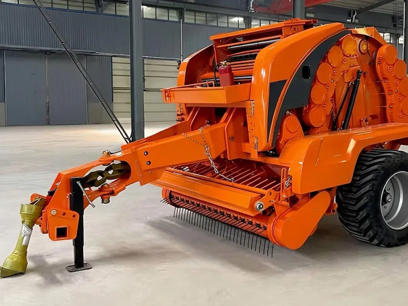
Material System: Where Under-Specification Creates Risk
Material selection at the component level has a measurable effect on how early mid-season failures occur. The U-joint cross is the most material-critical component in the driveshaft assembly. A cross manufactured from 20CrMnTi carburised steel — case-hardened to 58–62 HRC at the surface with a ductile core — can absorb the impact peaks that occur during slug feeding without crack initiation at the surface. A cross made from plain carbon steel heat-treated to a through-hardened condition is uniformly brittle and fractures rather than deforming when an overload spike bypasses the slip clutch. In practice, this material difference often separates a $40 cross repair from a $400 full shaft assembly replacement.
| Część | Correct Material Spec | Failure Risk with Substandard Material |
|---|---|---|
| U-joint cross | 20CrMnTi carburised, 58–62 HRC surface | Brittle fracture at overload peaks, cup shoulder cracking |
| Bearing cups | 52100 bearing steel, precision ground | Spalling, premature needle roller wear |
| Telescoping tubes | Q345 cold-drawn, epoxy or galvanised | Surface rust, binding, fretting debris |
| Jarzma | SAE 1045 forged, normalised | Ear crack propagation, yoke distortion under shock |
| Guard tube | UV-stabilised HDPE | Early embrittlement, crop fire risk |
Operational Factors That Accelerate Failure
Incorrect PTO Speed
Running a 1000 RPM baler input at 540 RPM does not reduce wear — it increases torque demand for the same power output by nearly double, loading the driveline far beyond its operating design point. Conversely, running a 540 RPM baler above its rated input speed generates heat in the gearbox and causes bearing cage fracture at the input shaft. Most CASE IH and John Deere 9-Series round balers specify 1000 RPM operation; confirming the correct tractor PTO output speed before engagement is a fundamental check that is regularly skipped on borrowed or unfamiliar equipment.
Excessive Operating Angle
Every degree above the manufacturer’s recommended maximum articulation angle increases cyclic velocity variation at the baler input — and raises the bending load on the U-joint cross by approximately the square of the angle. A standard driveshaft that works correctly at 15° will experience roughly four times the bending stress at 30°. Operators who regularly turn at the headland without disengaging the PTO, or who use a tractor with an incompatible hitch geometry for the baler’s tongue length, are consistently operating the shaft above its rated angle. This is particularly common in smaller paddocks in New Zealand, the UK, and northern France where headland space is limited.
Missed Lubrication
The U-joint bearing cups and the telescoping tube splines both require regular EP grease replenishment. Most manufacturers specify a greasing interval of 8 hours of operation for the U-joints and 20 hours for the spline profile under normal conditions — more frequently in wet or silage baling environments where water contamination washes grease out of the needle roller contact zone. A dry U-joint running at 1000 RPM generates frictional heat in the bearing cup that causes the needle rollers to pit and spall within a single working shift. By the time vibration and noise are audible, the cup bore is already damaged and the cross must be replaced.
Replacement Shaft Built for CASE IH Round Balers
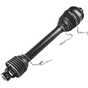
EP PTO Shaft for CASE IH Round Balers
Engineered as a direct-fit round baler PTO shaft replacement for CASE IH round baler platforms. The assembly uses a 20CrMnTi carburised cross with precision-ground 52100 bearing cups, Q345 cold-drawn telescoping tubes with corrosion-resistant coating, and an overload-protected slip clutch. The front yoke accommodates 1-3/8 in. × 6 spline and 1-3/8 in. × 21 spline tractor outputs — covering the range of CASE IH tractors commonly paired with these balers across North America, Australia, and Western Europe. The guard assembly carries CE certification and meets ASABE S331 guarding requirements.
Diagnosing a Round Baler PTO Shaft Before It Fails
The most effective way to avoid a mid-season breakdown is a structured pre-shift check that takes less than five minutes. The physical condition of the shaft tells most of the story before any failure produces audible noise. The following diagnostic sequence covers the highest-risk failure points in order of the likelihood that a problem will be present:
Step 1 — U-joint Radial Play
With the shaft stationary and the tractor PTO disengaged, grip each joint cross firmly and attempt to move it radially within the yoke. Any perceptible movement — even 0.3 mm — indicates bearing cup wear. A cross that has measurable play will fail within a short number of operating hours under full baling load.
Step 2 — Telescoping Action
Manually compress and extend the shaft through its full travel range. The movement should be smooth and consistent with light hand force. If the tubes stick, require significant effort to move, or produce a scraping sound, the spline contact surfaces need immediate greasing; if greasing does not resolve the binding within one working cycle, the tubes require replacement before the spline profile is further eroded.
Step 3 — Slip Clutch Torque
A slip clutch that releases under normal baling load — not during a blockage event — has either lost its spring preload through fatigue or has glazed friction discs that can no longer develop adequate clamping force. Test this by checking whether the clutch holds engagement during a normal crop pass without slipping. A clutch that nuisance-slips during routine baling is not protecting the driveline; it is wearing itself out and allowing the baler to run intermittently on reduced power.
Step 4 — Guard and Weld Integrity
Inspect the outer tube weld seam at both yoke connections and along the tube body for visible cracks or surface discolouration from localised heat. Weld toe cracks propagate rapidly under the cyclic bending load of normal operation. Also confirm that all guard end cones are present and retain their mounting collars securely — a loose cone that contacts the rotating shaft at operating speed generates enough heat to ignite dry hay in minutes.
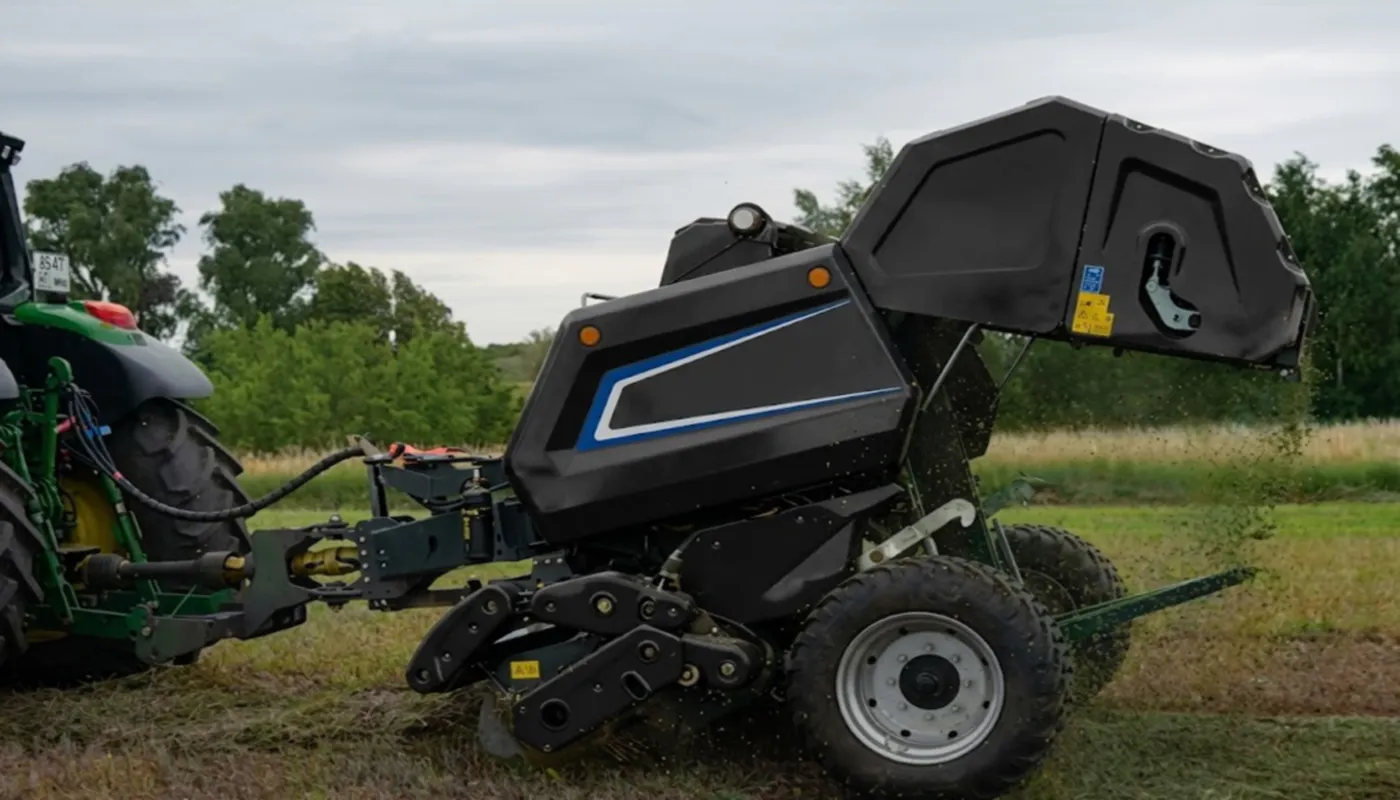
Slip Clutch Calibration: The Most Overlooked Pre-Season Task
The slip clutch on a round baler PTO shaft is the primary line of defence against driveline damage during a blockage event. When it is set correctly, it releases cleanly at a torque level that protects the gearbox and the driveshaft without nuisance-slipping under normal crop loads. When it is set incorrectly — in either direction — it either fails to protect or it becomes an active contributor to shaft deterioration.
Set too loose: The clutch slips repeatedly during normal baling conditions — particularly in dense first-cut grass or wet silage. Each slip event heats the friction discs, progressively glazing the friction surface. A glazed disc transfers heat inconsistently and eventually fails to release during a real blockage, allowing the full stall torque to reach the gearbox input. Operators often misread this as a gearbox problem when the clutch is the actual failure origin.
Set too tight: The clutch exceeds the baler gearbox’s maximum allowable input torque during blockage events. Repeated peak loads of this kind fracture the input shaft bearing cage, distort the gearbox housing, and in severe cases crack the gearbox casing itself — failures that require full gearbox replacement rather than a clutch disc kit.
Correct calibration procedure: Refer to the baler operator’s manual for the specified clutch release torque range. The torque is adjusted by tightening or loosening the compression nut on the spring stack. After adjustment, verify the setting by observing clutch behaviour during intentional blockage simulation — not during normal crop conditions. Re-check the setting every 40–50 working hours throughout the season, as friction disc wear slightly reduces the effective spring preload over time.
Related Driveline Components
A round baler PTO shaft operates within a complete drivetrain. When shaft-level failure analysis points to driveline under-specification or gearbox overload as contributing factors, sourcing the adjacent components from a coordinated range eliminates compatibility ambiguity and simplifies parts management across a mixed baler fleet.
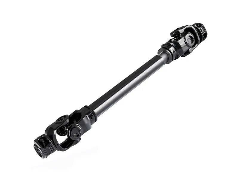
Multi-series driveshaft configurations designed for operations running balers across different tractor models through the season. When a failed shaft is being replaced mid-season and the specific OEM replacement is unavailable in the local supply chain, a universal configuration covering the required spline count, collapsed length, and series rating can be installed as a direct functional substitute. All series repair components — cross kits, guard tubes, friction clutch disc sets — remain fully interchangeable within the series group, keeping the parts inventory manageable.
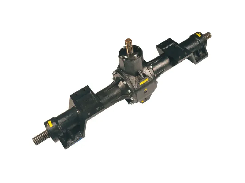
When shaft-level diagnostics reveal that repeated peak torque events have reached the baler gearbox input — a sign that the slip clutch was either set too tight or failed to release during overload — the gearbox itself needs inspection for input bearing and housing damage. Replacing a damaged gearbox alongside the new round baler PTO shaft from the same supply network ensures that the input spline profile, torque rating, and housing flange dimensions are already matched, removing the fitment uncertainty that arises when sourcing these components from different suppliers.
O producencie
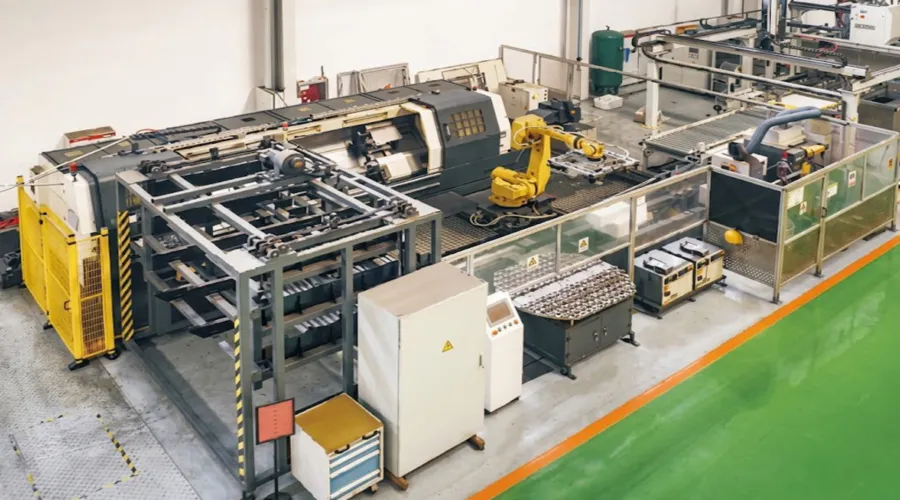
The manufacturing range spans agricultural gearboxes, worm gear reducers, planetary gear drives, power take-off shafts, hydraulic cylinders, gears, chains, and motors. All production is conducted under ISO 9001:2015 certification, applied across every stage from incoming material inspection through final assembly and pressure testing. Gearbox housings and mechanical assemblies are produced in ductile iron, cast iron, cast steel, precision cast steel, and cast aluminium, with the material grade selected according to the structural, thermal, and weight requirements of each application. Beyond the standard catalogue, the engineering team develops non-standard components — sprockets, worm gears, precision shafts, pulleys, and custom assemblies — produced to customer drawings or application descriptions, with written quotation available within 24 hours of receiving a datasheet or component photograph.
Warsztat



Często zadawane pytania
Redaktor: PXY