
General Buyer Guides & Comparison
A direct technical comparison of reduktor jednobiegowy architectures and dedicated worm gear reducer designs — examining efficiency figures, torque density, self-locking behaviour, and total cost of ownership across the low-speed, high-torque applications where both product types are regularly specified in parallel.
Understanding the Terminology: What Is a Single Speed Reducer vs. a Worm Gear Reducer?
The phrase reduktor jednobiegowy and the phrase “worm gear reducer” are not mutually exclusive — a single speed reducer is a gearbox that achieves its ratio in one stage of gear reduction, and a worm gear reducer is a type of single-stage or multi-stage gearbox that uses a worm-and-wheel gear pair as its reduction mechanism. In the WP-series product family, the terms overlap entirely: every unit in the WPKA, WPKS, WPZ, WPKZ, and WPDS ranges is simultaneously a single speed reducer and a worm gear reducer. When buyers and engineers use these terms in a comparison context — “single speed reducer vs. worm gear reducer” — they typically mean one of two distinct comparisons: a worm gear single-stage unit versus a worm gear multi-stage unit, or a worm gear design versus a different gear architecture (helical, bevel, or planetary) at the same stage count. This article addresses the more practically useful of the two comparisons.
The operational question most engineers face is not whether to use a single-stage or two-stage worm unit per se, but whether to choose a jednobiegowa przekładnia ślimakowa at all for a low-speed, high-torque application — or whether a different gear architecture such as a helical inline or helical-bevel unit would serve better. That decision turns on five technical factors: mechanical efficiency, torque density per unit volume, ratio range in a single stage, self-locking capability, and thermal performance at the operating duty cycle. Each of these is examined below with reference to published performance data from the WP-series reduktor prędkości jednostopniowy product family.
Mechanical Efficiency: The Number That Matters Most for Energy Cost
Mechanical efficiency is where the worm gear reduktor jednobiegowy is most frequently criticised when compared with alternative gear architectures. A single-stage worm reducer at moderate reduction ratios (1/10 to 1/20) achieves approximately 80–90% mechanical efficiency — meaning 10–20% of the motor input power is converted to heat at the gear mesh rather than transmitted to the driven load. At higher ratios (1/30 to 1/60), efficiency drops further to 70–80%, and at the extreme 1/60 ratio, a well-designed worm unit may achieve only 68–75% efficiency depending on worm shaft surface finish, oil grade, and operating temperature. By contrast, a single-stage helical inline gearbox of equivalent ratio achieves 97–99% efficiency at any ratio up to approximately 1/8, and a helical-bevel right-angle unit achieves 94–97% efficiency. The efficiency gap between worm and helical architectures is real and quantifiable.
The practical consequence depends entirely on duty cycle and input power. A reduktor prędkości ślimakowej at 75% efficiency transmitting 1.5 kW input power wastes 375 W as heat continuously. Over 4,000 operating hours per year, that represents 1,500 kWh of electrical energy wasted annually compared with a helical alternative at 96% efficiency. For a facility in the UK or Netherlands where industrial electricity costs are significant, this energy cost gap may justify a helical unit despite its higher purchase cost, if the application genuinely allows it. For many low-speed, high-torque applications in agricultural and materials-handling contexts in Australia, Brazil, or South Korea, the efficiency gap is offset by the lower purchase cost, simpler installation, and self-locking capability that the worm reduktor jednobiegowy provides and helical units cannot match.
Efficiency Comparison Across Gear Architectures at Common Reduction Ratios
The table below compares published mechanical efficiency ranges for four gear architectures at reduction ratios relevant to low-speed, high-torque applications. These figures represent single-stage efficiency for helical, bevel, and worm units, and combined two-stage efficiency for helical-bevel units where applicable. All values assume correct lubricant type and grade, correct oil fill level, and operation within the rated thermal power limit of the unit.
| Gear Architecture | Ratio 1/5 – 1/10 | Ratio 1/15 – 1/30 | Ratio 1/40 – 1/60 | Self-Locking Capability |
|---|---|---|---|---|
| Worm gear (single stage) | 82–90% | 75–85% | 68–78% | Yes — at ratios above approx. 1/25 |
| Helical inline (single stage) | 97–99% | Not achievable in single stage | Not achievable in single stage | NIE |
| Helical-bevel right angle (two stage) | 95–97% | 93–96% | 90–94% | NIE |
| Planetary (single stage) | 97–99% | 95–98% | Not achievable in single stage | NIE |
| Cycloidal (single stage) | 92–95% | 90–94% | 88–92% | NIE |
Note: Worm gear efficiency decreases as ratio increases due to the increase in sliding friction at lower helix angles. The worm gear architecture is the only one in the above list that achieves ratios of 1/30 to 1/60 in a single stage in a standard right-angle housing format.
Where Worm Gear Single Speed Reducers Win: Ratio Range and Self-Locking
The worm reduktor jednobiegowy offers two capabilities that competing gear architectures cannot match in a comparable single-stage housing footprint. The first is ratio range: a single worm gear stage achieves ratios from 1/5 through to 1/60 within the same housing platform, covering the full spectrum of low-speed, high-torque applications from moderate-speed conveyor drives through to ultra-slow gate actuators and agitator systems. A helical inline unit requires three or more gear stages to approach a 1/60 ratio, which roughly triples the housing length and eliminates the right-angle shaft arrangement that makes the worm unit compact for 90° drive configurations. A helical-bevel unit achieves right-angle output and moderate ratios up to approximately 1/30 in two stages, but cannot reach 1/60 without a third stage, further increasing cost and envelope.
The second unique capability is self-locking. At worm helix angles below approximately 6° — which corresponds to ratios above approximately 1/25 in standard WP-series jednobiegowa przekładnia ślimakowa units — the friction at the tooth contact zone under reverse torque exceeds the tangential force from the load, causing the assembly to hold stationary without any external brake. This passive holding capability is fundamental to gate actuators, lifting mechanisms, valve drives, and positioning tables across industrial applications in Australia, South Korea, Canada, and the Netherlands, where the load must remain stationary between driven movements without relying on a powered brake coil. No helical, bevel, planetary, or cycloidal gear unit provides self-locking at any ratio — each requires an external mechanical or electromagnetic brake to hold load position when the motor is de-energised.

Manufacturing Structure & Material System of the WP-Series Single Speed Reducer
The efficiency and torque-capacity figures cited above are achievable only when the worm and wheel gear pair is manufactured to the dimensional and surface-finish standards the lubrication and load-distribution calculations assumed. Below-specification surface finish on the worm shaft, lower-tin-content bronze on the wheel, or misaligned housing bores all shift the effective efficiency toward the lower end of the published range and reduce the rated torque before the listed nameplate values. Understanding the material specification of the WP-series reduktor jednobiegowy platform helps buyers evaluate whether published efficiency claims are backed by verifiable engineering standards or are nominal best-case figures.
Housing — HT250 Cast Iron
Precision CNC-bored after casting to maintain the geometric relationship between worm shaft and worm wheel axes within tolerance. The bore accuracy directly affects gear mesh efficiency: a misaligned axis increases the proportion of sliding contact at the mesh interface and lowers effective efficiency below the published nominal. Housing fin geometry governs thermal equilibrium temperature, which in turn affects the working viscosity of the oil at the mesh and therefore the hydrodynamic film thickness contribution to efficiency.
Worm Shaft — 20CrMnTi, HRC 56–62
CNC thread-ground worm shaft with surface roughness Ra below 0.4 µm at the thread flanks. Surface finish is the primary determinant of the mixed-lubrication friction coefficient at the worm mesh — a smoother surface generates a thicker hydrodynamic film for the same oil grade and contact load, directly improving efficiency at the upper end of the published range. The gear mesh efficiency figures for the WP-series assume the ground thread specification, not a hobbed worm shaft finish.
Worm Wheel — ZCuSn10Pb1 Bronze
Centrifugally cast phosphor-bronze rim at 10% tin content. Higher tin content improves anti-friction properties at the worm mesh, reducing the friction coefficient and improving efficiency in the boundary-lubrication regime at low sliding speeds. The ZCuSn10Pb1 specification is the standard for industrial worm producenci przekładni ślimakowych targeting published efficiency at the upper end of the range; lower-tin alloys shift the friction coefficient toward the higher end, reducing efficiency.
Bearings — Rated for Worm Mesh Loads
Tapered roller bearings at the output shaft positions of larger frames, deep-groove ball bearings at the input on smaller frames. Bearing preload at assembly affects the bearing friction contribution to overall unit efficiency — approximately 0.5–2% of input power depending on bearing type and size. This bearing loss is included in the published mechanical efficiency figures for the WP-series reduktor jednobiegowy range and is not an additional deduction from the gear mesh efficiency figure.
Related Product
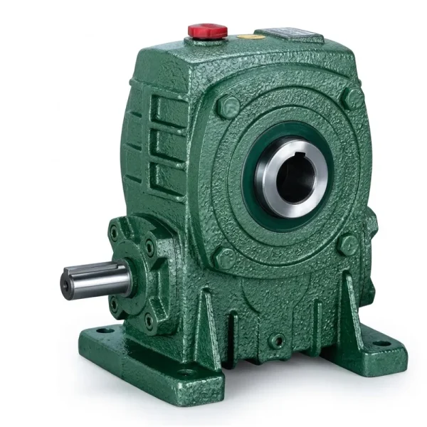
Przekładnia jednobiegowa EP-WPKA 5–260 kg
The EP-WPKA series is a horizontal-shaft reduktor jednobiegowy spanning frame sizes from 40 mm through 250 mm centre distance, covering unit weights from 5 kg to 260 kg. Five shaft configuration options (Types A through E) allow single-output, double-output, and dual-input machine layouts from the same housing platform. Published mechanical efficiency for the WPKA at ratios from 1/5 through 1/60 reflects the CNC thread-ground worm shaft and ZCuSn10Pb1 bronze wheel specifications described above — providing a directly comparable baseline when evaluating this reduktor jednobiegowy against helical-bevel alternatives for a specific low-speed, high-torque application.
Decision Framework: When to Specify a Worm Single Speed Reducer vs. a Helical Alternative
The efficiency comparison alone does not determine which gear architecture is correct for a specific application. Five factors in combination determine the right choice, and a jednostopniowy, kątowy reduktor prędkości z przekładnią ślimakową wins on three of them while losing on two. Understanding which factors dominate for the specific application resolves the selection question more reliably than any generalised recommendation.
Factor 1: Required Ratio in One Stage
Worm wins. Ratios from 1/5 to 1/60 in a single compact housing. Helical requires multiple stages above approximately 1/8; helical-bevel reaches 1/30 in two stages but not 1/60 in two. If the application genuinely needs 1/30 to 1/60 in a single unit at right angles, no helical alternative matches the worm’s compactness.
Factor 2: Passive Load Holding (Self-Locking)
Worm wins decisively. Gate actuators, lifting mechanisms, valve drives, and positioning systems where the load must hold without power all require self-locking. No helical, planetary, or bevel unit provides this — each requires an external brake. The worm reduktor ślimakowy jednostopniowy provides this inherently at ratios above 1/25, eliminating the brake and its associated cost and maintenance.
Factor 3: Mechanical Efficiency
Helical wins clearly. At equivalent ratios (where achievable), helical units achieve 93–99% efficiency vs. 68–90% for worm units. For continuous-duty, high-power applications where energy cost over the gearbox service life is a primary design criterion, the helical architecture pays back its higher cost difference in reduced electricity consumption — particularly at high input powers and high duty cycles in the UK, Netherlands, or Canada.
Factor 4: Noise Level
Worm wins. The sliding contact at the worm mesh generates considerably less gear noise than the rolling-contact impacts at helical tooth engagements. For food processing facilities in South Korea or pharmaceutical production environments in the UK where low gear noise is a regulatory or workplace concern, the worm przekładnia ślimakowa o wysokim momencie obrotowym typically meets acoustic requirements that helical units do not without additional housing damping treatment.
Factor 5: Shock Load Tolerance
Worm wins on absorption; loses on sustained overload. The bronze worm wheel deforms slightly under momentary overload, absorbing shock energy that would fracture a harder helical gear tooth. This makes the worm przekładnia ślimakowa more tolerant of start-up torque spikes and jamming events in agricultural and materials-handling applications in Brazil and Colombia. However, sustained overload above rated torque degrades the bronze wheel faster than equivalent steel-on-steel helical gear wear, so the shock tolerance does not apply to chronic overloading.
Total Cost of Ownership: Efficiency Is Only One Line in the Calculation
Engineers who evaluate gear architecture selection on efficiency alone regularly underspecify or overspecify their drivetrain. A complete total cost of ownership calculation for a reduktor prędkości przekładnia ślimakowa versus a helical alternative includes purchase cost, installation and alignment time, energy cost over service life, maintenance interval and cost, and the cost of any ancillary components (brakes, coupling guards, base plates) required specifically by one architecture and not the other. For most low-speed, high-torque applications in the 0.12 to 15 kW input power range covered by the WP-series reduktor jednobiegowy platform, the worm unit’s lower purchase cost, zero brake requirement at ratios above 1/25, and simpler direct-couple or foot-mount installation offset the energy cost premium of its lower efficiency at all but the highest duty cycles.
A practical example: a 1.5 kW worm reduktor prędkości ślimakowej at ratio 1/40 running 10 hours per day at 78% efficiency wastes approximately 330 W continuously, generating 1,188 kWh of waste heat per year. At an industrial electricity rate of 0.15 USD/kWh, this represents approximately 178 USD per year in energy cost premium versus a 95%-efficient helical alternative. If the helical unit costs 400–600 USD more than the worm unit at purchase and requires a 150–250 USD mechanical brake, the total extra cost of the helical architecture at year zero exceeds the annual energy savings — meaning the worm unit has a lower total cost over any service life under approximately 3–4 years in this scenario. For applications in high-electricity-cost regions like the UK or Netherlands, or for larger input powers where the wasted energy is proportionally greater, the helical option recovers its cost premium faster. This calculation should be performed application-specifically rather than accepting a generic recommendation.
Thermal Performance: The Worm Reducer’s Second Efficiency Constraint
The mechanical efficiency disadvantage of the worm reduktor jednobiegowy has a second-order consequence that directly constrains maximum continuous input power: all the lost efficiency becomes heat within the housing. A reduktor ślimakowy at 75% efficiency running 2.2 kW input is generating 550 W of heat continuously within the cast iron housing. The housing must dissipate this heat through natural convection and radiation from its exterior surface to the ambient air — and the rate at which it can do so is bounded by the housing surface area, fin geometry, and ambient temperature. When the heat generation rate exceeds the maximum dissipation rate, the oil temperature rises beyond the lubricant’s operating limit, accelerating degradation.
This thermal limit manifests as the thermal power rating on the nameplate — the maximum continuous input power the housing can sustain at a declared ambient temperature without exceeding the oil temperature limit. For larger WP-series frames at high ratios in warm climates, the thermal power rating may be lower than the mechanical power rating — meaning the housing thermal capacity, not the gear mesh strength, is the binding constraint on how much motor power can be connected. Helical and planetary units at equivalent mechanical power ratings do not carry a separate thermal power limit, because their 95–99% efficiency generates so little heat that the housing thermal capacity is never the binding constraint. This absence of a thermal power limit is a practical operating advantage of high-efficiency gear architectures in high-ambient-temperature or high-duty-cycle applications in Australia, Brazil, or South Korea that worm reduktor jednobiegowy users must plan around either through correct input power selection or auxiliary cooling.
Compatible Products for Complete Drive Systems
Ten reduktor jednobiegowy is one component in a complete drivetrain. Motor selection, coupling type, and gearbox specification all interact to determine the system’s real-world efficiency and total cost of ownership. The following product categories are dimensionally matched to the WP-series worm reducer platform.
Silniki elektryczne

The efficiency comparison between gear architectures must include the motor. A correctly matched motor operating at its rated load point achieves higher motor efficiency than an oversized motor at partial load — which shifts the total drivetrain efficiency calculation in favour of an optimised motor-reducer combination even when the reducer alone is less efficient than an alternative architecture. Verified IEC frame motor-reducer pairings for the WP-series are available for direct specification.
Przekładnia ślimakowa

For applications requiring ratios beyond the 1/60 single-stage maximum — where the efficiency comparison with helical alternatives becomes even more important to document — the two-stage worm gearbox range extends compound ratios from 1/200 through 1/900. The efficiency of a two-stage worm arrangement compounds the single-stage figure: two stages each at 78% efficiency produce an overall efficiency of approximately 61%, which reinforces the case for evaluating a high-efficiency alternative when total input power and duty cycle allow it.
Często zadawane pytania
Redaktor: PXY