
Mining & Quarrying · Technical Analysis
A comparative engineering review for procurement engineers, maintenance managers, and drive system designers across open-pit copper, iron ore, coal, and aggregate operations in Australia, Canada, Chile, South Africa, and Europe.
The bucket wheel excavator, rope shovel crowd drive, and bucket elevator hoist systems that define open-pit mining operations are among the most mechanically punishing drive applications on the planet. Each time a loaded bucket bites into a rock face or drops its contents onto a transfer point, a shock torque travels back through the drive train — a transient that can reach 3 to 5 times the steady-state rated torque within milliseconds. How that transient is absorbed or resisted is the central engineering question in comparing a Ein-Gang-Reduziergetriebe to a hydraulic coupling arrangement.
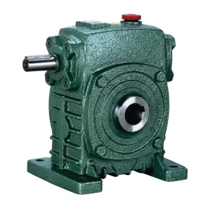
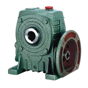
Hydraulic couplers — fluid couplings and hydrodynamic torque converters — were the historical answer: they absorb shock by slipping, protecting the motor from inrush and the drive train from peak transients. A well-specified einstufiges Untersetzungsgetriebe with a matched shock-load service factor, however, handles the same transients through controlled structural compliance in the gear mesh and housing, without the energy loss, maintenance overhead, and heat-generation penalties that hydraulic couplers impose in sustained high-duty operation. This article examines the engineering basis for that comparison and identifies the EP-WPKS and EP-WPDKA series Schneckengetriebe products as reference designs for specific open-pit bucket drive applications.
The Shock Load Problem in Open-Pit Bucket Drive Systems
Open-pit bucket applications generate shock torque by two distinct mechanisms. The first is impact loading: when a bucket or dipper tooth strikes an unbroken rock face or a buried boulder, the tool decelerates abruptly and the inertia of the rotating drive train delivers a torque spike into the transmission. The second is release loading: when the tool breaks through overburden and suddenly loses its resistance, the drive train accelerates rapidly and the reversal of torque direction stresses the gear teeth in a mode they are not continuously loaded in — the back-face of each tooth engages the mating surface, and if clearance (backlash) is present, this engagement is an additional impact event.
Hydraulic couplers address both mechanisms through slip: the impeller and runner are never mechanically locked, so the fluid coupling absorbs the transient by allowing relative rotation between input and output. The penalty is continuous slip loss (typically 2–5% of transmitted power even at steady state), heat generation in the oil, and a maintenance requirement for the coupling fluid that is separate from and additional to the reducer lubricant system. In a bucket wheel excavator running continuously for 20 hours per day in the Pilbara or the Atacama Desert, these losses and maintenance demands accumulate to a substantial operating cost. The case for a correctly specified single speed worm reducer or a Schneckengetriebe is that the shock-load service factor applied during selection provides the necessary structural margin without the continuous energy dissipation that makes the hydraulic coupler expensive over the machine’s service life.

How Service Factor Selection Makes the Single Speed Reducer Viable for High-Impact Duty
The AGMA standard for Schneckengetriebe (AGMA 6034) defines service factors for different load categories. The base factor for a smooth, uniform load with no shock is 1.0. For moderate shock (starts under load, occasional impact) the factor is 1.25–1.5. For heavy shock — the classification that applies to bucket wheel and rope shovel crowd drives — the factor is 1.75–2.5 or higher depending on starts-per-hour frequency. Applying a 2.0 service factor to a 15 kW motor drive means selecting a reducer rated for 30 kW steady-state output before entering the torque table. The resulting unit has roughly twice the tooth contact area, housing wall thickness, and bearing capacity of the minimum-viable unit, and this structural excess is what absorbs the shock torque without yielding.
The hydraulic coupler, by contrast, does not require a service factor multiplication on the mechanical components downstream of the coupler — because the coupler itself limits the torque transmitted. The penalty is that the coupler must be sized for the full stall torque of the motor (approximately 3× rated torque for a standard squirrel-cage motor), and the heat generated during a stall event must be dissipated into the coupler fluid and housing. In an open-pit environment where ambient temperatures regularly reach 35–45 °C and the equipment operates in direct sunlight, thermal management of the hydraulic coupler becomes a genuine engineering challenge that adds component cost and maintenance complexity without improving the fundamental reliability of the drive train. A properly specified Ein-Gang-Reduziergetriebe avoids this entirely.
Manufacturing Structure of a High-Duty Single Speed Reducer
The worm is machined from a single case-carburising alloy steel billet (20CrMnTi or equivalent), case-hardened to HRC 58–62, and thread-flanks ground to Ra 0.4–0.8 µm. An integral shaft eliminates the press-fit joint that could migrate under the cyclic shock loads of bucket drive service, ensuring the worm geometry remains constant throughout the reducer’s service life.
The tooth ring is centrifugally cast in ZCuSn10Pb1 tin phosphor bronze, then rough-machined, shrink-fitted to the ductile iron hub, and finish-hobbed as a composite assembly. Centrifugal casting produces a denser, more uniform alloy microstructure than sand casting, which improves fatigue strength under the repetitive shock loading of an open-pit bucket drive cycle compared to a conventionally cast wheel.
The housing is cast in GGG50 ductile iron with external ribbing to maximise torsional and bending stiffness without unnecessary mass. The bore centrelines are machined in a single datum setup — worm shaft bore, worm wheel bore, and all flange faces are produced in one chucking — ensuring the perpendicularity and centre-distance accuracy that determines load distribution across the tooth face.
Material System for Open-Pit Mining Duty
Standard WP-series Ein-Gang-Reduziergetriebe construction uses ZCuSn10Pb1 bronze wheels and 20CrMnTi worm shafts — material choices validated across decades of industrial conveyor and mixer drives. For the more severe duty of open-pit bucket applications, two material upgrades are commonly specified. The first is a move from tin bronze to aluminium bronze (ZCuAl10Fe3Mn2, equivalent to CuAl10Fe4Ni4) for the wheel tooth ring: aluminium bronze has higher compressive yield strength and better resistance to pitting fatigue under high contact stress, trading the tin bronze’s superior conformability for greater fatigue life under the high-cycle shock loading of a bucket drive. The second upgrade is the specification of carburised and ground worm shafts machined from 18CrNiMo7-6 rather than 20CrMnTi, adding nickel to improve core toughness under the bending shock loads that accompany each bucket impact event.
Housing material in the larger frame sizes (centre distance 200 mm and above) transitions to cast steel (ZG310-570) rather than ductile iron, providing greater tensile strength and fracture toughness for the shock-loaded support structure. All external machined surfaces receive a two-component epoxy primer followed by a polyurethane topcoat — the coating system is specified for resistance to the alkaline or acidic mine water, diesel exhaust particulate, and UV exposure of an open-pit environment rather than the neutral indoor industrial environment assumed by standard catalogue paint specifications.
Single Speed Reducer vs Hydraulic Coupler — Comparative Summary
The table below compares the two drive train configurations across the criteria that most affect total cost of ownership in an open-pit bucket application. The comparison assumes equivalent rated torque capacity at the output shaft and a continuous-duty cycle of 18–20 operating hours per day.
| Criterion | Ein-Gang-Reduziergetriebe | Hydraulic Coupler |
|---|---|---|
| Steady-state efficiency | 70–85% (worm); 94–97% (helical) | 95–98% at design slip (3–5% slip) |
| Shock torque absorption | Via service factor margin in gear mesh | Via fluid slip — inherent soft start |
| Heat generation in service | Low — proportional to efficiency loss | Significant — slip energy dissipated as heat |
| Maintenance interval | Oil change 2000–4000 hr; bearing check annually | Fluid change 1000–2000 hr; thermal plug inspection per shift |
| Hot climate performance | Reduced efficiency margin; uprate one frame at >40 °C | Heat dissipation problematic above 40 °C ambient |
| Motor protection | External overload relay required | Inherent — torque limited by fluid fill |
| Space envelope | Compact — reducer replaces coupler + gearbox | Coupler adds axial length between motor and gearbox |
| Spare parts complexity | Worm wheel + bearing set + seals | Coupler + fusible plug + fluid + gearbox parts separately |
Recommended Products for Open-Pit Bucket Drive Applications

Thermal Management in Open-Pit High-Temperature Environments
Open-pit operations in the Pilbara (Western Australia), the Atacama (Chile), and the Northern Cape (South Africa) routinely record ambient temperatures of 40–50 °C on the bench surface where drive equipment is installed. At these temperatures, the oil-film viscosity in a Schneckengetriebe drops below the design minimum, reducing the film thickness that separates the worm flank from the wheel tooth. The consequence is mixed-lubrication contact — partial metal-to-metal contact — which accelerates wear and increases the rate of heat generation in a feedback loop that can lead to rapid thermal failure if not addressed at the specification stage.
Three engineering responses are available. The first is uprating by one frame size: selecting a reducer with a centre distance and housing thermal dissipation area one step larger than the minimum calculation indicates, providing additional thermal mass and surface area to dissipate the increased heat generation at elevated ambient temperature. The second is specifying a synthetic PAO (polyalphaolefin) gear oil rather than a mineral oil: synthetic PAO ISO VG 460 maintains its viscosity index better at 50 °C than mineral oil of the same grade, sustaining a thicker film and lower contact temperature at the same operating point. The third is fitting an external oil cooling circuit — a small shell-and-tube heat exchanger in the reducer oil circuit, cooled by a fan-driven air blast — which is standard practice on the highest-power bucket wheel excavator drives in Australian and Chilean operations. The Ein-Gang-Reduziergetriebe supports all three responses; the hydraulic coupler, already generating heat from slip loss, compounds the thermal management problem rather than alleviating it.
Maintenance Advantage of the Single Speed Reducer in Open-Pit Service
The maintenance profile of a einstufiges Schneckengetriebe on an open-pit bucket drive consists of three primary activities: oil changes at 2000–4000-hour intervals, periodic oil sampling and analysis, and bearing inspection and replacement at intervals determined by the bearing L10 life calculation for the actual load and speed conditions. All three activities are performed on a single component at a single location in the drive train. Parts inventory requires worm wheel bronze tooth rings (consumed components that can be replaced without disturbing the housing or shaft), input and output bearing sets, and shaft seals.
A hydraulic coupler installation adds its own maintenance schedule in parallel: coupling fluid changes at 1000–2000-hour intervals, inspection and replacement of the thermoplastic fusible plug (the over-temperature protection device that vents fluid on thermal overload), and periodic inspection of the coupler element for erosion from fluid recirculation. The fusion plug replacement is particularly disruptive in an operating mine — on many equipment designs it requires partial disassembly of the motor-coupler-gearbox train and results in coupling fluid spillage that creates a contamination and housekeeping issue in the drive station. Over a 20-year machine life, the cumulative maintenance labour saving from eliminating the hydraulic coupler and its associated maintenance activities is consistently identified as the primary driver of the Schneckendrehzahlreduzierer choice in total-cost-of-ownership analyses conducted by Australian and Canadian open-pit operators.

Installation and Alignment Considerations for Bucket Drive Reducers
In an open-pit mine, drive equipment is mounted on structural steel frames that are subject to thermal expansion, ground settlement, and vibration from blasting operations in adjacent areas. A Ein-Gang-Reduziergetriebe installation on a bucket elevator or stacker-reclaimer drive must account for these base movements through flexible mounts or precision shimming rather than assuming a permanently fixed datum. The hollow-shaft torque-arm configurations of the EP-WPKS and EP-WPDKA series are particularly well-suited to these conditions: the torque arm rubber bush absorbs minor base movement without transmitting secondary bending into the reducer housing, and the shrink-disc output connection maintains zero-backlash coupling to the drive shaft without the keyway stress concentration that causes shaft fatigue failures on impulse-loaded drives.
For coupled configurations where the reducer has a solid output shaft driving the bucket elevator head shaft through a flexible coupling, shaft alignment must be within 0.05 mm parallel and 0.05°/100 mm angular before the coupling element is fitted. In the field conditions of an open-pit mine, achieving and maintaining this alignment requires the use of laser alignment equipment rather than dial gauges — the thermal growth of the base frame during a production shift can shift the cold-alignment result by 0.1–0.3 mm, and only a laser system allows the running-temperature alignment to be measured and corrected without stopping the drive. This is standard practice for primary drive alignment on bucket wheel excavators in German and Australian open-cut operations.
Manufacturing Background
Our production facility has accumulated more than ten years of engineering depth in mechanical power transmission for industrial, agricultural, and mining applications. Every Ein-Gang-Reduziergetriebe leaving our production floor is processed under ISO 9001:2015 quality management certification — from raw material traceability and in-process dimensional gauging through final load-test verification. The manufacturing range covers agricultural gearboxes, worm gear reducers, planetary gear drives, power take-off shafts, hydraulic cylinders, precision gears, roller chains, and electric motors. Structural components are produced in ductile iron, cast iron, cast steel, precision investment-cast steel, and aluminium alloy to match the load, temperature, and environmental requirements of each product application. Gears, worm shafts, sprockets, pulleys, and output shafts are finished on multi-axis CNC hobbing, grinding, and turning centres to DIN and ISO standards. Customers requiring a complete open-pit bucket drive train — reducer, motor, coupling, and mounting hardware — can source all elements through a single technically accountable supplier.
Werkstatt




Compatible Drive Components — One-Stop System Supply
A complete open-pit bucket drive station requires matched motor and reducer specifications. The following complementary product lines are available from the same manufacturing source, allowing procurement teams to source a fully verified drive train rather than coordinating separate vendor qualifications.


Häufig gestellte Fragen
Herausgeber: PXY