Seite wählen

Universeller Drehzahlminderer

Produkte ansehen
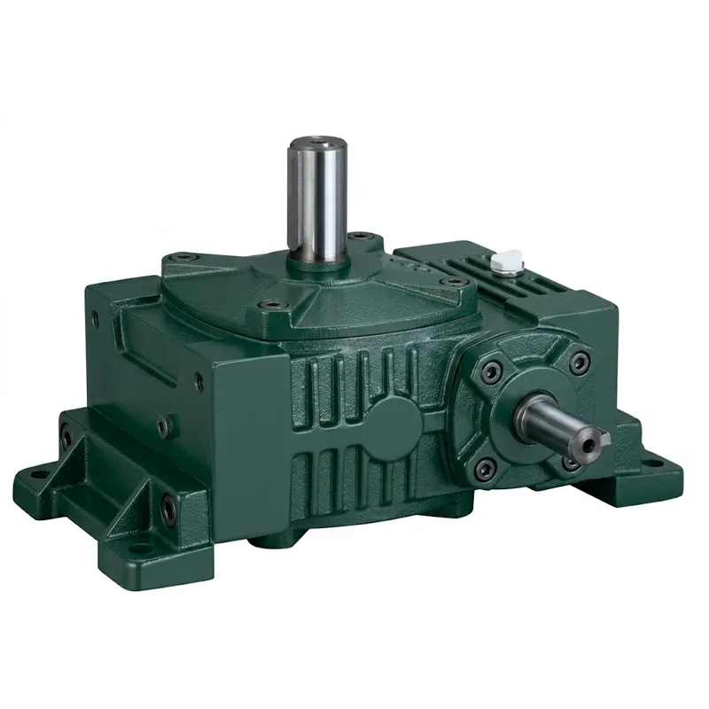
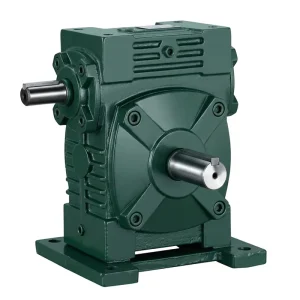
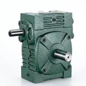
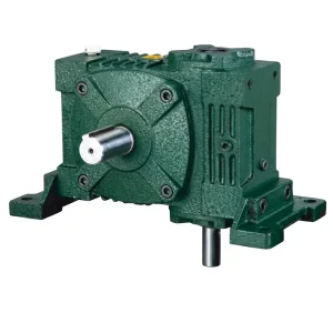
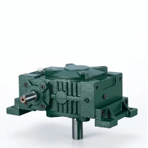
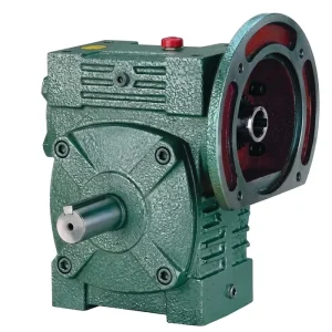
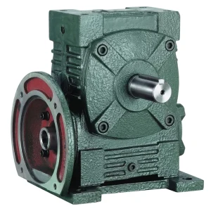
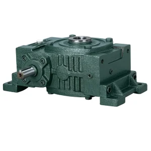
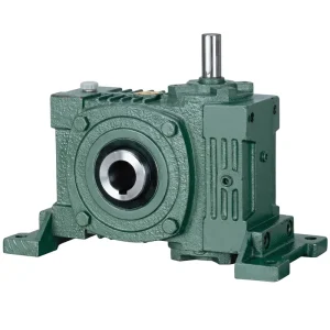
superiortransmissioninc products EP WPWO Universal Speed Reducer

universal speed reducer is a self-contained mechanical gearbox designed to accept a high-speed motor input and deliver a precisely reduced output speed at proportionally increased torque. The term “universal” refers to the unit’s ability to be configured in multiple shaft orientations — typically between three and six mounting arrangements within a single product family — making one physical unit suitable for a wide variety of machine layouts without modification to the housing or internal gear set.

At the core of every universal speed reducer in the worm-gear category is a 90-degree crossed-axis gear pair: a hardened alloy steel worm shaft meshes with a phosphor bronze worm wheel. As the worm rotates, its helical thread pushes the wheel teeth forward, producing smooth speed reduction in a compact envelope. Unlike multi-stage helical or planetary gearboxes, a single worm stage can deliver ratios from 5:1 to 60:1 — covering the speed range required by the vast majority of low-speed industrial process machinery.

Up to 60 : 1

Single-stage reduction ratio — no compound stages needed

90°

Shaft crossing angle — input and output shafts perpendicular

Self-Locking

Inherent at ratios ≥ 1/30 — no separate brake required

3 – 6 Orientations

Shaft configurations per family — one SKU, multiple layouts

What Makes Up a Universal Speed Reducer?

Internal Components & Their Functions

A universal speed reducer is more than a housing with two shafts. Each component inside is chosen to balance torque capacity, thermal performance, and service life. Understanding the role of each part is essential for correct selection and predictable maintenance planning.

① Gear Housing

Material: HT200 grey cast iron

The housing is the structural backbone of the universal speed reducer. Manufactured from HT200 grey cast iron — precision-machined on all mating surfaces, bearing bores, and shaft exits — it combines tensile strength (~200 MPa) with inherent vibration damping from the graphite microstructure in the cast iron matrix. The heavy wall sections absorb both static mounting loads and dynamic shock impulses without distortion, preserving gear-mesh alignment over thousands of operating hours. Foot and flange mounting provisions are machined simultaneously to guarantee positional accuracy between motor and output shaft.

② Worm Shaft (Input)

Material: 20CrMnTi alloy steel, case-hardened HRC 58–62

The worm shaft transmits motor torque directly into the gear mesh. It is manufactured from 20CrMnTi alloy steel, carburised to build a hard case layer, then precision-ground on thread flanks to Ra 0.8 μm. This surface finish ensures the initial sliding contact between worm and wheel is immediately in a favourable regime — reducing the running-in wear period significantly compared to unground alternatives. The shaft is supported by preloaded angular contact or taper roller bearings to manage the combined radial and axial thrust forces generated by the helical thread geometry during torque transmission.

③ Worm Wheel (Output Gear)

Material: ZCuSn10Pb1 phosphor bronze

The worm wheel is the output element of the universal speed reducer gear pair. Centrifugally cast from ZCuSn10Pb1 phosphor bronze — a material selected for its low friction coefficient against hardened steel, excellent thermal conductivity, and natural resistance to galling — the wheel rim is hobbed on CNC gear-cutting equipment to DIN 3974 tolerance class. The bronze rim is shrunk and keyed onto a cast iron or steel hub, giving the load-bearing bore the structural strength of ferrous metal while retaining the tribological advantage of bronze at the sliding contact surface.

④ Output Shaft

Material: Alloy steel, ground and keyed

The output shaft carries the worm wheel and transmits reduced-speed, high-torque rotation to the driven load. It is machined to h6 tolerance on the bearing seating diameters and to h8 on the coupling engagement zone, with a precision-cut parallel keyway conforming to GB/T 1095. For horizontal-output universal speed reducers, taper roller bearings manage the combined radial and axial loads at the output end. For vertical-output variants, the shaft points downward and is typically coupled directly to agitator paddles, mixer impellers, or hoisting drums without an additional shaft coupling.

⑤ Bearings

Type: Taper roller (≥ size 80) / Deep-groove ball (smaller)

Bearing selection is one of the most consequential design decisions in a universal speed reducer, because bearing life directly limits gearbox service intervals. Taper roller bearings are used on the worm shaft of size 80 and larger frames — their combined radial-axial load capacity is well-suited to the thrust loads generated by the helical worm thread at rated torque. All bearings are sourced to C3 internal clearance class, providing thermal expansion tolerance during warm-up from ambient to steady-state operating temperature. Proper preload adjustment during assembly is verified on each unit before oil fill and dispatch.

⑥ Shaft Seals & Breather

Type: NBR double-lip radial seals + breather vent

NBR (nitrile rubber) double-lip radial shaft seals are fitted at every shaft exit to prevent lubricant migration into connected motor housings or downstream machinery — a failure mode that causes significant secondary damage in gearmotor assemblies. A breather vent fitted to size 100 and larger frames equalises internal air pressure during thermal cycling, preventing the pressure differential that would otherwise force oil past the shaft seals over time. The breather design includes a sintered bronze filter element to prevent airborne particulate ingress in dusty industrial environments — a common concern in agricultural processing and mining applications.

⑦ Gear Oil

Grade: ISO VG 220 mineral (standard)

The lubricant in a universal speed reducer is not a consumable to be overlooked — it is an active load-bearing element in the gear mesh. ISO VG 220 mineral gear oil, pre-filled at the factory, provides the viscosity film required to separate the worm shaft thread flanks from the bronze wheel tooth surface at operating temperature. The oil is splash-lubricated at rated input speeds, ensuring the mesh zone remains flooded during continuous operation. First oil change is recommended at 500 operating hours; subsequent changes every 2,500–3,000 hours depending on ambient temperature and duty cycle severity.

⑧ Motor Adaptor / Input Flange

Standard: IEC 72-1 frame alignment

The motor input side of a universal speed reducer is engineered to accept IEC 72-1 standard frame motors through a machined adaptor flange. The flange bore is piloted to h6 tolerance to precisely register the motor shaft centre with the gearbox worm shaft axis — critical for minimising angular misalignment that would introduce additional radial load on the input bearings. Motor stub shaft engagement with the gearbox input shaft is typically through a keyed coupling or solid-bore arrangement. Both arrangements are interchangeable at the point of order, allowing the same universal speed reducer body to accommodate different motor coupling philosophies without internal modification.

How to Select the Right Universal Speed Reducer

1. Determine Required Output Speed

2. Calculate Required Output Torque

3. Choose the Output Configuration

4. Verify Thermal Rating & Environmental Fit

superiortransmissioninc-Worm Reducer-show

Quick Selection Checklist

✔Required output speed (RPM) confirmed

✔Output torque calculated with service factor applied
✔Shaft orientation (horizontal / vertical) decided
✔Motor position and shaft-direction config (A–F) selected
✔Thermal rating checked for continuous duty
✔IP rating and sealing confirmed for environment
✔Self-locking requirement checked (ratio ≥ 1/30)
✔Output shaft keyway dimensions match coupling bore