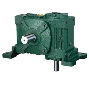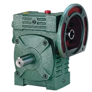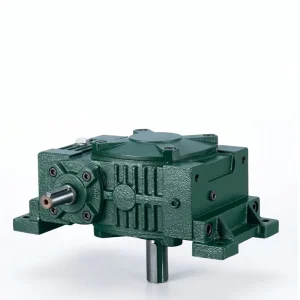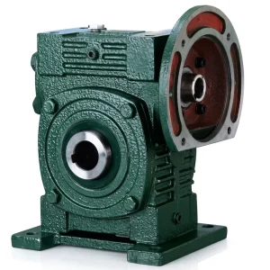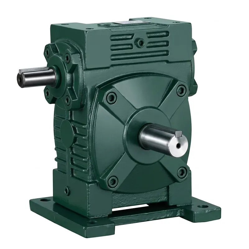
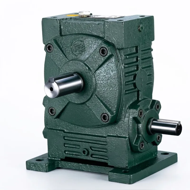
EP-WPWA-S Universal-Geschwindigkeitsreduzierer
Der EP-WPWA-S ist ein kompakter, robuster Universal-Getriebe Basierend auf der bewährten WPW-Schneckengetriebearchitektur ist diese Baureihe in zwei Gehäusevarianten erhältlich: WPWA (horizontaler Eingang, Vollsockelmontage) und WPWS (Flanscheingang). Sie deckt Baugrößen von 40 bis 250, Drehmomentbereiche bis zur Lastklasse 350 kg und Untersetzungsverhältnisse von 1/5 bis 1/60 ab. Das Ergebnis ist eine einzige Produktfamilie, die den Großteil der Anforderungen an langsam laufende, drehmomentstarke Antriebe in Industrie und Landwirtschaft erfüllt, ohne dass für jede Anwendung eine individuelle Anpassung erforderlich ist.
Das entscheidende mechanische Merkmal jedes Schneckengetriebes dieser Klasse ist der 90°-Wellenwinkel zwischen Ein- und Ausgang. Dank dieser Geometrie lässt sich das EP-WPWA-S in Antriebsstrangkonfigurationen integrieren, in denen Inline- oder Parallelgetriebe unpraktisch sind – beispielsweise zwischen einem Motor und einem Förderbandantrieb im rechten Winkel oder als Wendepunkt in einer mehrachsigen Verpackungslinie. Das Schneckengetriebe bietet zudem einen inhärenten Rücklaufwiderstand, wodurch in vielen Anwendungen ein separater Bremsmechanismus entfällt und sowohl die Anzahl der Bauteile als auch der Wartungsaufwand reduziert werden.
Die flexible Wellenrichtung ist einer der entscheidenden praktischen Vorteile der WPW-Serie. Fünf Standardkonfigurationen der Wellenrichtung – A bis E – decken verschiedene Kombinationen ab, darunter Eingang links/Ausgang rechts, Eingang oben, Doppelausgang und verlängerte Wellenanordnung. Dadurch kann dasselbe Gehäuse in unterschiedlichen Anlagenlayouts für verschiedene Einbaulagen verwendet werden, wodurch sich die Anzahl der benötigten Ersatzteile für Technik- und Wartungsteams deutlich reduziert. Das EP-WPWA-S wird als Einzelgerät geliefert. Schneckengetriebe Die Einheit kann entweder als Einheit oder in Kombination mit einem passenden Elektromotor als motorisiertes Schneckengetriebeaggregat ausgeführt werden, je nach den Systemintegrationsanforderungen des Kunden.
EP-WPWA-S Universal-Geschwindigkeitsreduzierer
WPW-Serie Schneckengetriebe – Baugröße 40–250 | Übersetzungsverhältnis 1/5–1/60 | Tragfähigkeit bis 350 kg
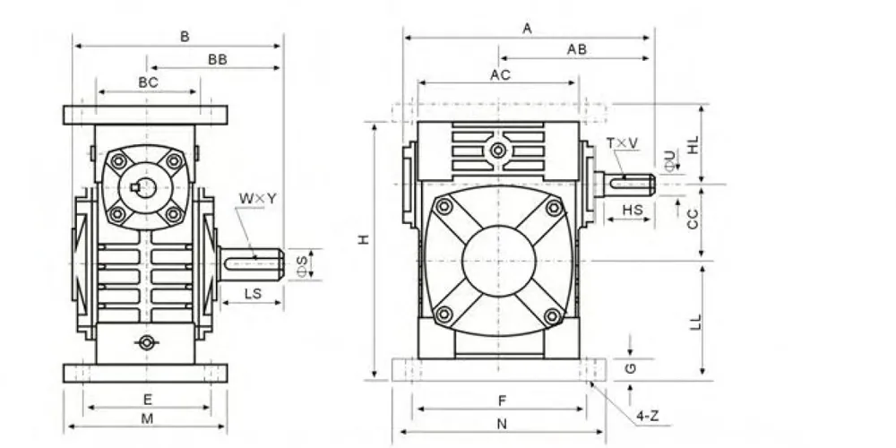
EP-WPWA-S Technische Spezifikationen — Dimensionsdaten
| Größe | Verhältnis | A | AB | B | BB | Klimaanlage | BC | CC | HL | LL | H | M | N | E | F | G | Z | HS | U | T×V | Gewicht (kg) |
|---|---|---|---|---|---|---|---|---|---|---|---|---|---|---|---|---|---|---|---|---|---|
| 40 | 1/5 | 143 | 87 | 114 | 74 | 95 | 61 | 40 | 45 | 60 | 135 | 100 | 130 | 80 | 110 | 10 | 10 | 25 | 12 | 4×2,5 | 4.5 |
| 50 | 1/10 | 175 | 108 | 150 | 97 | 111 | 68 | 50 | 50 | 80 | 165 | 120 | 140 | 95 | 110 | 12 | 12 | 30 | 12 | 5×3 | 7.5 |
| 60 | 1/15 | 198 | 120 | 168 | 112 | 127 | 76 | 60 | 60 | 93 | 195 | 130 | 150 | 105 | 120 | 18 | 12 | 40 | 15 | 5×3 | 11.5 |
| 70 | 1/20 | 231 | 140 | 194 | 131 | 152 | 86 | 70 | 73 | 108 | 233 | 150 | 190 | 115 | 150 | 18 | 15 | 40 | 18 | 5×3 | 15.5 |
| 80 | 1/25 | 261 | 160 | 214 | 142 | 169 | 102 | 80 | 83 | 123 | 268 | 170 | 220 | 135 | 180 | 18 | 15 | 50 | 22 | 7×4 | 24 |
| 100 | 1/30 | 322 | 190 | 254 | 169 | 216 | 117 | 100 | 100 | 150 | 330 | 200 | 270 | 155 | 220 | 20 | 15 | 50 | 28 | 10×4,5 | 39 |
| 120 | 1/40 | 371 | 219 | 282 | 190 | 256 | 124 | 120 | 120 | 180 | 305 | 230 | 320 | 180 | 260 | 25 | 18 | 65 | 30 | 7×4 | 57 |
| 135 | 1/50 | 422 | 249 | 317 | 210 | 296 | 147 | 135 | 135 | 215 | 455 | 250 | 350 | 200 | 290 | 30 | 18 | 75 | 35 | 10×4,5 | 85 |
| 155 | 1/60 | 497 | 295 | 382 | 252 | 345 | 185 | 155 | 155 | 235 | 493 | 280 | 380 | 220 | 320 | 32 | 20 | 85 | 40 | 18×7 | 110 |
| 175 | 1/60 | 534 | 314 | 373 | 255 | 374 | 192 | 175 | 160 | 260 | 558 | 310 | 410 | 250 | 350 | 37 | 21 | 85 | 45 | 14×5,5 | 152 |
| 200 | 1/60 | 580 | 342 | 426 | 319 | 412 | 230 | 200 | 175 | 290 | 620 | 355 | 445 | 290 | 390 | 45 | 24 | 95 | 50 | 20×7,5 | 216 |
| 250 | 1/60 | 705 | 420 | 552 | 385 | 500 | 285 | 250 | 200 | 350 | 750 | 460 | 560 | 380 | 480 | 50 | 28 | 110 | 60 | 25×9 | 350 |
Fünf Hauptvorteile des universellen Schneckengetriebes EP-WPWA-S
① Breites Rahmengrößenspektrum
Elf Baugrößen von 40 bis 250 ermöglichen es Ingenieuren, die Abmessungen und das Drehmoment präzise auf die angetriebene Maschine abzustimmen – ohne die Kosten und das Gewicht durch Überdimensionierung in die Höhe zu treiben. Eine Einheit der Größe 40 wiegt 4,5 kg, eine der Größe 250 350 kg. Diese Bandbreite deckt alles ab, vom kleinen Förderbandantrieb in einer Lebensmittelverarbeitungsanlage bis zum Hochleistungsrührwerk in einem chemischen Reaktor.
② Konfigurationen der Richtung flexibler Wellen
Fünf Wellenrichtungsoptionen (A–E) sind in derselben Gehäusefamilie integriert. Ob Standard-Einlass links/Auslass rechts, Einlass oben oder eine Erweiterung mit zwei Ausgängen – das Universal-Getriebe EP-WPWA-S ist ohne Sonderanfertigungen kompatibel. Dies ist ein entscheidender Vorteil für OEMs, die Maschinen für den Export in verschiedene Märkte mit unterschiedlichen Einbauraumbedingungen entwickeln.
③ Auswahl eines breiten Reduktionsverhältnisses
Sechs Standarduntersetzungsverhältnisse – 1/5, 1/10, 1/15, 1/20, 1/25, 1/30, 1/40, 1/50 und 1/60 – ermöglichen eine präzise Einstellung der Ausgangsdrehzahl ohne Zwischenstufen. Bei Anwendungen mit einem Schneckengetriebeuntersetzungsverhältnis von 1/60 sorgt die selbsthemmende Wirkung des Schneckengewindes für einen funktionalen Rücklaufwiderstand. Dadurch entfällt in vielen Anwendungen mit vertikaler Belastung oder schwerkraftunterstützten Förderanlagen die Notwendigkeit einer separaten Haltebremse.
④ Gehäuse aus Gusseisen für Stabilität und Wärmeableitung
Das gerippte Gusseisengehäuse erfüllt zwei Funktionen gleichzeitig: Es sorgt für die nötige Stabilität unter den Biegemomenten, die durch die Wellenüberhanglasten entstehen, und die äußere Rippengeometrie vergrößert die Oberfläche zur passiven Wärmeableitung im Dauerbetrieb. Bei Umgebungstemperaturen bis zu 40 °C – Standard in vielen Industrieumgebungen in Südostasien, dem Nahen Osten und Äquatorialafrika – hält das WPW-Gehäuse die Sumpftemperaturen ohne Zwangskühlung im akzeptablen Bereich.
⑤ Direkte Motorflanschmontage
Die WPWS-Variante verfügt über einen IEC-genormten Eingangsflansch, der die direkte Motormontage ohne Kupplung oder Zwischenhalterung ermöglicht. Diese kompakte Bauweise mit motorisiertem Schneckengetriebe reduziert die axiale Baulänge, macht die Wellenausrichtung überflüssig und verkürzt die Montagezeit erheblich – ein praktischer Vorteil für Maschinenbauer in Europa, Australien und Nordamerika, wo die Montagekosten einen wesentlichen Teil der Maschinenkosten ausmachen.
Wie funktioniert ein Schneckengetriebe? – Funktionsprinzip des EP-WPWA-S
Das Funktionsprinzip eines Universal-Getriebe Bei der WPW-Familie beginnt alles mit der Schneckenwelle – dem Antriebselement. Die Schnecke ist ein spiralförmiges Gewinde, das auf eine gehärtete Stahlwelle gefräst ist und im 90-Grad-Winkel mit einem Schneckenrad kämmt: einem Zahnrad aus Bronze oder Gusseisen mit gebogenen Zähnen, die das Schneckengewinde umschließen. Mit jeder Umdrehung der Schnecke wird das Schneckenrad um eine Zahnteilung weiterbewegt – wodurch die Drehzahlreduzierung und die entsprechende Drehmomentverstärkung entstehen, die das Verhalten eines Schneckengetriebes bestimmen.
Das Untersetzungsverhältnis eines Schneckengetriebes ergibt sich aus der Anzahl der Zähne des Schneckenrades geteilt durch die Anzahl der Gewindegänge. Eine eingängige Schnecke, die in ein 60-zahniges Schneckenrad eingreift, ergibt ein Übersetzungsverhältnis von 1/60 – sechzig Motorumdrehungen für jede Abtriebsumdrehung, was einer 60-fachen Drehmomentsteigerung (abzüglich Wirkungsgradverlusten) entspricht. Das Universal-Untersetzungsgetriebe EP-WPWA-S ist über seinen gesamten Übersetzungsbereich so konstruiert, dass Steigungs- und Eingriffswinkel so gewählt sind, dass ein optimales Verhältnis zwischen mechanischem Wirkungsgrad und Selbsthemmung erreicht wird, da diese beiden Eigenschaften mit zunehmendem Übersetzungsverhältnis gegenläufig wirken.
Bei höheren Untersetzungsverhältnissen wird der Steigungswinkel flacher, die Reibung steigt, und das Getriebe nähert sich einem selbsthemmenden Zustand, in dem das Rückdrehmoment der Last die Eingangswelle nicht mehr drehen kann. Dies ist vorteilhaft bei Hebe- oder Indexieranwendungen, geht aber mit einem geringeren Wirkungsgrad einher. Bei niedrigeren Untersetzungsverhältnissen – 1/5, 1/10 – ist der Wirkungsgrad höher, und das Getriebe kann rückwärts angetrieben werden. Das Verständnis dieses Zielkonflikts ist entscheidend für die korrekte Dimensionierung eines Getriebes. Schneckendrehzahlreduzierer von einem Getriebe, das entweder unter Last überhitzt oder eine unnötige Haltebremse benötigt. Aus diesem Grund enthält das Datenblatt des Universal-Getriebes EP-WPWA-S Wirkungsgradkurven über den gesamten Übersetzungsbereich.

Werkstoffe und Fertigungsstandards
Das Gehäuse des Universal-Getriebes EP-WPWA-S ist aus Grauguss nach GB/T 9439 HT200 gefertigt – der gleichen Werkstoffgüte, die auch für Schwerlast-Werkzeugmaschinenbetten verwendet wird und hier aufgrund ihrer hervorragenden Schwingungsdämpfungseigenschaften und guten Bearbeitbarkeit gewählt wurde. Nach dem Guss wird das Gehäuse auf einem Bearbeitungszentrum präzisionsgebohrt. Die Positionstoleranzen der Lagerbohrungen betragen dabei ±0,02 mm. Dies gewährleistet die korrekte Wellenparallelität und die optimale Schneckenrad-Kontaktgeometrie über die gesamte Lebensdauer des Gehäuses, unabhängig von der Einbaulage.
Die Schneckenwelle besteht aus 20CrMnTi-Einsatzstahl, der aufgekohlt und auf eine Einsatzhärtungstiefe von 0,8–1,2 mm und eine Oberflächenhärte von 58–62 HRC gehärtet wurde. Diese Härte, kombiniert mit den Druckeigenspannungen der aufgekohlten Schicht, verleiht den Flanken des Schneckengewindes eine hohe Verschleißfestigkeit, selbst unter den beim Start-Stopp-Zyklus auftretenden Grenzschmierungsbedingungen. Der Schneckenradkranz besteht aus Phosphorbronze (ZCuSn10Pb1), die im Schleudergussverfahren auf eine Nabe aus Sphäroguss gegossen wird. Die Bronze sorgt für geringe Reibung und gute Anpassung an die gehärtete Schneckenflanke, während die Nabe aus Sphäroguss die Torsionskräfte ohne Risiko eines Sprödbruchs auf die Abtriebswelle überträgt.
Die Lager der Ein- und Ausgangswelle sind Rillenkugellager auf der Schneckenwelle und Kegelrollenlager auf der Schneckenradwelle (ab Baugröße 100), wobei bei Wellenüberhang die axiale Belastbarkeit den Ausschlag gibt. Alle Lager sind mit einer Lagerluft der Klasse C3 für den Betrieb bei erhöhten Temperaturen ausgestattet. Die Lagergehäuse verfügen über integrierte Öldichtungen, die für das im Ölsumpf des Universal-Getriebes EP-WPWA-S verwendete Mineralöl ausgelegt sind. Der IEC-genormte Eingangsflansch der Variante WPWS ist so gefertigt, dass Motoren ohne Unterlegscheiben direkt montiert werden können.

Anwendungsszenarien – Wo der universelle Drehzahlminderer EP-WPWA-S zum Einsatz kommt
Förderbandantriebe für Lebensmittel und Getränke – Europa und Australien
Hygienische Förderanlagen in Lebensmittelverarbeitungsbetrieben in Deutschland, Frankreich und Australien nutzen den Universal-Untersetzungsmotor EP-WPWA-S mit Übersetzungen von 1/20 bis 1/40, um Band- und Lamellenförderer mit kontrollierter Geschwindigkeit anzutreiben. Das Gusseisengehäuse ermöglicht eine problemlose Reinigung mit Nassspülung an den Wellendichtungsstellen. Dank der 90°-Geometrie befindet sich der Motor außerhalb des Produktbereichs – ein entscheidender Vorteil in den beengten Grundrissen von Abfüll- und Verpackungshallen.
Antriebsstränge für Landmaschinen – USA & Brasilien
Getreideförderschneckenantriebe, Saatgutdosiersysteme und Düngerstreuer im US-amerikanischen und brasilianischen Landmaschinensektor setzen auf kompakte Bauweise. Schneckengetriebe Um die Drehzahl von Zapfwelle oder Elektromotor auf die für Bodenbearbeitungs- oder Getreideförderanlagen erforderliche niedrige Drehzahl und das hohe Drehmoment zu reduzieren, ist der universelle Drehzahlminderer EP-WPWA-S in den Größen 70–120 erhältlich. Er deckt den Drehmomentbereich ab, der für die meisten mittelgroßen Landmaschinen benötigt wird.
Materialtransport- und Hebezeuge — Südostasien
In Produktions- und Lagerhallen in Malaysia, Vietnam und Thailand ersetzt das EP-WPWA-S mit Übersetzungen von 1/50 bis 1/60 und Selbsthemmungsfunktion die mechanischen Bremsen an Vertikalachsen-Hebe- und Torantrieben. Der inhärente Rücklaufwiderstand eines hochübersetzten Schneckengetriebes hält die Lastpositionen ohne aktive Bremsung – dies reduziert den Stromverbrauch und eliminiert die Bremsenwartung im Mehrschichtbetrieb.
Fahrten zu Chemie- und Wasseraufbereitungsanlagen – Naher Osten und Südkorea
In Wasser- und Abwasseraufbereitungsanlagen in Südkorea und den Golfstaaten werden Rührwerksantriebe, Ventilantriebe und Dosierpumpenantriebe mit robusten Schneckengetrieben in großen Baugrößen eingesetzt. Die Baureihe EP-WPWA-S (175–250) bewältigt die kontinuierlichen Drehmomentbelastungen von langsam laufenden Mischanwendungen. Dank der niedrigen Ausgangsdrehzahl und der hohen Drehmomentverstärkung durch das Übersetzungsverhältnis von 1/60 entfällt die Notwendigkeit zusätzlicher Untersetzungsstufen.
Hersteller von Schneckengetrieben
Unser Werk fertigt seit über zehn Jahren mechanische Kraftübertragungstechnik für ein breites Produktspektrum: Landwirtschaftliche Getriebe, Schneckengetriebe, Planetengetriebe, Nebenabtriebswellen, Hydraulikzylinder, Zahnräder, Kettenräder und kundenspezifische Baugruppen. Das Werk ist nach ISO 9001:2015 zertifiziert, und die Qualitätskontrolle ist in den gesamten Prozess integriert – von der Wareneingangsprüfung der Gussrohlinge bis hin zur abschließenden Drehmoment- und Zahnflankenspielprüfung der fertigen Getriebe.
Wir entwickeln und fertigen Bauteile aus Sphäroguss, Gusseisen, Stahlguss, Präzisionsstahlguss und Aluminiumguss. Dabei produzieren wir sowohl Standardprodukte aus unserem Katalog als auch Sonderanfertigungen nach Kundenzeichnung. Dieselbe Fertigungsanlage, die Schneckengetriebegehäuse mit Bohrungstoleranzen von ±0,02 mm herstellt, fertigt auch Zahnräder, Kettenräder, Schneckengetriebe, Riemenscheiben, Schneckenwellen und weitere Antriebskomponenten – alles unter einem Dach. Diese vertikale Integration gewährleistet Maßgenauigkeit bei allen zusammenpassenden Teilen und eine zentrale technische Verantwortung für den gesamten Antriebsstrang.
Werkstatt




Kompatible Produkte – Komplettes Antriebssystem aus einer Hand
Der EP-WPWA-S ist so konzipiert, dass er direkt mit Standard-IEC-Motorgehäusen und unserem gesamten Sortiment an Antriebszubehör kompatibel ist – es werden keine kundenspezifischen Adapter benötigt.
Die Kombination des EP-WPWA-S mit einem passenden Elektromotor ergibt eine motorisierte Schneckengetriebeeinheit, die direkt installiert werden kann. Unser Elektromotorenprogramm umfasst ein- und dreiphasige IEC-Motoren von 0,18 kW bis 22 kW – dimensioniert für die jeweilige Nenndrehzahl und -leistung der WPW-Baugröße und des Untersetzungsverhältnisses.

Über die WPW-Serie hinaus umfasst unser komplettes Schneckengetriebeprogramm die Gehäusetypen NMRV, RV, WD und CW – mit Untersetzungsverhältnissen von 1:5 bis 1:100 in kompakten Aluminium- und robusten Gusseisengehäusen. Sollte das Übersetzungsverhältnis oder die Montagekonfiguration des EP-WPWA-S nicht exakt passen, findet unser technisches Team eine Alternative aus unserem umfangreichen Schneckengetriebekatalog, ohne dass ein Lieferantenwechsel erforderlich ist.

Häufig gestellte Fragen
Frage 1: Wie funktioniert ein Schneckengetriebe, und warum eignet sich das EP-WPWA-S für den Dauerbetrieb industrieller Antriebe in Südostasien?
Ein Schneckengetriebe wandelt die Rotation eines schnelllaufenden Motors mit niedrigem Drehmoment in eine langsamlaufende Ausgangsleistung mit hohem Drehmoment um. Dies geschieht durch den Eingriff einer gehärteten Schneckenwelle in ein Schneckenrad aus Bronze im 90°-Winkel. Jede Umdrehung der Schnecke verschiebt das Schneckenrad um eine Zahnteilung – wodurch die für den Antrieb charakteristische Drehzahlreduzierung und Drehmomentverstärkung erzielt werden. Das Universal-Getriebe EP-WPWA-S eignet sich für Dauerbetrieb in warmen Industrieumgebungen wie beispielsweise in Malaysia, Vietnam und Thailand. Das gerippte Gusseisengehäuse sorgt für passive Wärmeableitung im Dauerbetrieb, das Schneckenrad aus Phosphorbronze behält auch unter Dauerlast eine gute Anpassungsfähigkeit, und die in größeren Baugrößen verwendeten Kegelrollenlager nehmen die axialen Dauerlasten von Förderband- und Rührwerksantrieben ohne häufige Nachjustierung auf.
Frage 2: Welchen Zweck hat ein Universal-Untersetzungsgetriebe im Antriebssystem einer Landmaschine auf einem US-amerikanischen oder brasilianischen Bauernhof?
In der Landwirtschaft dient ein Universal-Untersetzungsgetriebe dazu, die hohe Drehzahl eines Elektromotors oder einer Zapfwelle in die deutlich niedrigere Drehzahl und das höhere Drehmoment umzuwandeln, die für den korrekten Betrieb von Bodenbearbeitungs- oder Getreideförderanlagen erforderlich sind. Ein Särad, das mit 1500 U/min läuft, führt zu Fehlbelegungen; eines, das mit 25 U/min läuft – der Ausgangsdrehzahl eines Schneckengetriebes mit einem Übersetzungsverhältnis von 1:60 – sorgt für eine präzise Saatgutverteilung. Das Universal-Untersetzungsgetriebe EP-WPWA-S wird in Getreideförderschnecken, Düngerverteilungssystemen und Förderbandübergabestellen in den landwirtschaftlichen Anbaugebieten des Mittleren Westens der USA und des brasilianischen Cerrado eingesetzt, da seine kompakte 90°-Geometrie in die engen Anbaurahmen von Traktoren und Anhängegeräten passt.
Frage 3: Welches Schneckengetriebe-Untersetzungsverhältnis sollte ein Ingenieur einer europäischen Lebensmittelverarbeitungsanlage für ein Förderband mit einer Geschwindigkeit von 15 Metern pro Minute wählen?
Das korrekte Übersetzungsverhältnis hängt von der Drehzahl des Eingangsmotors und dem Durchmesser des Antriebsritzels bzw. der Antriebsscheibe an der Abtriebswelle ab. Der Ingenieur berechnet zunächst die erforderliche Ausgangsdrehzahl und teilt dann die Eingangsdrehzahl durch diesen Wert, um das Übersetzungsverhältnis zu ermitteln. Bei einem 1400-U/min-Motor, der eine 200-mm-Riemenscheibe mit 15 m/min antreibt, beträgt die erforderliche Ausgangsdrehzahl etwa 24 U/min, was ein Zielübersetzungsverhältnis von ungefähr 1/58 ergibt. Die nächstliegende Standardauswahl im Universal-Getriebebausatz EP-WPWA-S ist 1/60.
Frage 4: Wo kann ein australischer Anlageningenieur ein universelles Ersatz-Untersetzungsgetriebe finden, das zu den Wellenabmessungen und Befestigungsschraubenmustern der WPW-Serie passt?
Die WPW-Serie ist eine standardisierte Gehäusefamilie, die herstellerübergreifend nach einheitlichen Maßvorgaben gefertigt wird. Achsabstand, Wellendurchmesser, Keilwellenabmessungen und Schraubenmuster sind in der Norm definiert und variieren nicht je nach Hersteller. Ein Ersatz-Universalgetriebe der WPW-Baugröße 100 hat beispielsweise unabhängig vom Hersteller des Originalgetriebes ein A-Maß von 322 mm, einen Abtriebswellendurchmesser von 50 mm und eine T×V-Keilwelle von 10×4,5 mm. Für australische Anlagenplaner, die einen direkten Ersatz suchen, genügt es, die Baugröße und das Übersetzungsverhältnis auf dem Typenschild des vorhandenen Getriebes zu überprüfen, um ein kompatibles EP-WPWA-S-Universalgetriebe zu spezifizieren. Eine Messung aller Maße vor Ort ist nicht erforderlich.
Q5. Sind Schneckengetriebe ausreichend geeignet, um die Drehzahl bei langsam laufenden Misch- und Rührvorgängen in südkoreanischen Chemieanlagen effektiv zu reduzieren?
Ja – Schneckengetriebe gehören zu den effektivsten einstufigen Untersetzungsmechanismen, um mit einem Standardmotor sehr niedrige Ausgangsdrehzahlen zu erreichen. Bei einem Übersetzungsverhältnis von 1/60 erzeugt ein 1400-U/min-Motor in einer einzigen Untersetzungsstufe, ohne Zwischenzahnräder, etwa 23 U/min an der Abtriebswelle. Für Misch- und Rührantriebe in Chemieanlagen in Südkorea – wo Schlammeindickungs- und Chemikaliendosierprozesse ein anhaltendes Drehmoment bei niedriger Drehzahl erfordern – bietet das Universal-Untersetzungsgetriebe EP-WPWA-S in den Baugrößen 175 oder 200 die Kombination aus niedriger Ausgangsdrehzahl, hoher Drehmomentverstärkung und Eigenbremswirkung. Dadurch ist es die praktische Vorzugslösung gegenüber Untersetzungsgetrieben mit paralleler Welle, die zwei Untersetzungsstufen benötigen, um die gleiche Ausgangsdrehzahl zu erreichen.
Frage 6: Wann ist der beste Zeitpunkt für den Einbau eines Schneckengetriebes, und welches Ölbefüllverfahren sollten die Wartungsteams im Nahen Osten bei hohen Umgebungstemperaturen befolgen?
Die Installation des Schneckengetriebes sollte idealerweise vor der Montage der angetriebenen Maschine erfolgen, um den Zugang zu den Befestigungsschrauben und der Wellenkupplung von allen Seiten ohne Behinderung zu gewährleisten. Bei den in Industrieanlagen der Golfstaaten typischen hohen Umgebungstemperaturen (40–50 °C) sollte der Ölsumpf des Universal-Getriebes EP-WPWA-S mit Mineralöl der Viskositätsklasse ISO VG 220 oder VG 320 anstelle des üblicherweise empfohlenen VG 150 befüllt werden, da die höhere Viskosität den Viskositätsabfall bei erhöhten Ölsumpftemperaturen ausgleicht.
Geben Sie Ihren EP-WPWA-S Universal-Geschwindigkeitsreduzierer an
Nennen Sie uns Ihre Eingangsdrehzahl, das erforderliche Ausgangsdrehmoment, das Übersetzungsverhältnis und die Wellenrichtung – wir bestätigen Ihnen die richtige Größe und Konfiguration für Ihre Anwendung.
Herausgeber: PXY