
Packaging & Logistics | Labeling Equipment
A technical reference for packaging line engineers, labeling machine OEMs, and logistics facility maintenance teams examining the mechanical role of worm gear speed reducers in label web transport, container indexing, and label application drives.
Label registration accuracy — the precise alignment of a printed label on a container — is one of the most demanding positional tolerances in packaging machinery. A pressure-sensitive label that lands 2 mm off-centre on a premium bottle in the UK or a 1 mm skew on a pharmaceutical vial in Canada is a production reject. The root cause of registration failure in automated labeling equipment is almost always a speed variation somewhere in the drive train: between the label web feed roll and the container conveyor, between consecutive labeling heads, or between the label dispenser and the applicator drum. The Ein-Gang-Reduziergetriebe — specifically a worm gear single reduction unit — is the drive component that eliminates these variations by imposing a mechanically fixed speed ratio between motor and driven shaft that does not drift under load or temperature change.
Modern pressure-sensitive and sleeve labeling machines, as well as glue-applied wrap-around labelers, operate at line speeds from 100 to over 600 containers per minute. At those throughput rates, the label web must advance in precise synchronisation with container movement across every single cycle. A einstufiges Untersetzungsgetriebe positioned in the drive train of each functional sub-system — web feed, container infeed starwheel, applicator drum, and outfeed conveyor — maintains the speed relationship that registration accuracy depends on.

The Mechanics of Label Registration and Why Drive Speed Matters
Label registration is maintained by keeping the label web advance speed and the container linear speed in a fixed, repeatable ratio at the point of label transfer. In a pressure-sensitive labeling machine, this ratio is typically 1:1 — the web surface and the container surface travel at the same speed at the nip point so the label transfers without stretching or wrinkling. Any variation in either speed causes the label to land ahead of or behind its target position on the container. At 400 containers per minute, a 0.5% speed deviation causes a registration error of approximately 1.2 mm per cycle — enough to fail the visual inspection standard in pharmaceutical, cosmetics, and premium beverage markets in Australia, the Netherlands, and South Korea.
Der Schneckendrehzahlreduzierer maintains this ratio by locking the output shaft speed to the motor input speed through a fixed gear mesh. Unlike a belt transmission where the effective drive ratio changes slightly as the belt wears, or a friction drive where the ratio is load-dependent, the worm gear single reduction produces the same output speed at every cycle as long as the motor runs at its rated frequency. This deterministic speed behaviour is what makes the einstufiges Schneckengetriebe the preferred drive element in registration-critical packaging applications worldwide.
Output speed is determined solely by the worm-to-wheel tooth count ratio — not by belt tension, friction coefficient, or applied torque magnitude.
The rigid mesh of worm and wheel eliminates the elastic deformation under load that causes periodic speed variation in timing belt and chain-drive labeling systems.
Worm gear sliding mesh produces low torque ripple, preventing the micro-speed pulses that cause label web flutter and application position scatter at high line speeds.
Self-locking tendency at higher reduction ratios holds the label web reel position during index pauses, preventing web creep that shifts the starting position of the next label.
Fertigungsstruktur
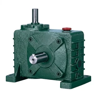
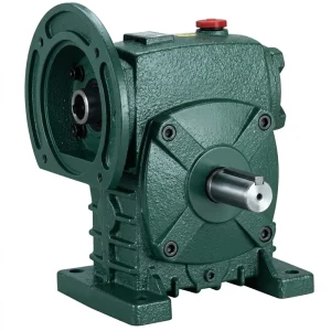
Die WP-Serie Einspeichen-Getriebe is built around an integral one-piece cast iron housing that encloses the worm shaft and worm wheel in a sealed single cavity. For labeling machine applications, this mono-block architecture is particularly important because the machine frame transmits vibration from the label web tension system, the applicator drum bearing loads, and the intermittent shock of container starwheel indexing into every bolted connection on the frame. A split-casing housing accumulates micro-movement at its joint faces over time, which eventually alters the gear mesh geometry and introduces speed ripple that the label registration system cannot compensate for.
The worm shaft and worm wheel sit perpendicular to one another within this housing, creating the right-angle drive layout that labeling machine designers regularly exploit to route the motor alongside or below the label web path without intersecting the film transport plane. The flange-input configuration connects the motor directly to the reducer input face — a particularly compact arrangement that avoids the intermediate coupling bracket required by separate-mount motor and gearbox combinations. Output shaft options include single solid shaft, double solid shaft, and hollow bore, allowing the reducer to drive label web feed rolls, applicator drum shafts, or container conveyor sprockets through whichever mechanical interface the machine design requires.
Materialsystem
Material choices in a Schneckengetriebe for labeling equipment must balance mechanical precision with resistance to the packaging facility environment: adhesive aerosol from label application, cleaning solvents used on glue-applied labelers, and the continuous low-amplitude vibration of a high-speed production line.
| Komponente | Material | Relevance to Labeling Machine Service |
|---|---|---|
| Gehäuse | Druckgusseisen | Rigid under the cyclic tension loads of label web feed; good vibration damping reduces mesh noise transmitted to the machine frame and label registration sensors |
| Schneckenwelle | Einsatzgehärteter legierter Stahl | Ground thread profile maintains precise tooth mesh geometry across the millions of cycles a labeling machine accumulates over its operating life; resists surface fatigue under repeated web tension load reversals |
| Schneckenrad | Zinnbronze | Self-lubricating tendency under partial-film lubrication reduces friction heat; gradual and predictable wear rate allows remaining service life to be estimated from periodic inspection without unexpected failure |
| Wellendichtungen | NBR / PTFE Lip Seals | Prevent lubricant migration onto label web surfaces — critical in adhesive labeling where oil contamination prevents label bond adhesion to container surfaces |
| Lager | Deep Groove / Taper Roller | Handle combined radial and axial loads from label web tension forces and applicator drum reaction loads; rated for continuous duty at high-speed labeling cycle rates |
| Schmiermittel | ISO VG 220 / 460 Gear Oil | Maintains viscosity at elevated sump temperatures reached during high-speed continuous labeling; oil capacity 0.4 – 5.2 L by model size |

Performance Parameters for Labeling Machine Drive Selection
The following table outlines the WP-series einstufiges Untersetzungsgetriebe specifications most relevant to labeling machine drive systems. Parameters are drawn from the standard product range and annotated with guidance specific to label registration applications.
| Parameter | Spezifikationsbereich | Labeling Application Notes |
|---|---|---|
| Eingangsleistung | 0,12 – 15 kW | Label web feed drives: 0.12 – 0.75 kW; container conveyor drives: 0.37 – 2.2 kW; applicator drum drives: 0.37 – 1.5 kW |
| Eingangsgeschwindigkeit | 750 – 2000 U/min | Matches 4-pole 50 Hz (1440 rpm) and 60 Hz (1728 rpm) motors across EU, AU, UK, CA, KR, BR labeling markets |
| Reduktionsverhältnis in einer Stufe | 1/10 – 1/60 | Container infeed starwheels: 1/15 – 1/30; label web feed rolls: 1/10 – 1/20; outfeed conveyor drives: 1/10 – 1/25 |
| Ausgangsdrehmoment | 6 – 6050 N·m | Label web tension drives require modest torque; container infeed drives require higher torque at start-up to accelerate container mass from rest |
| Gehäusemodellgröße | Größe 40 – 250 | Size 40–60 commonly used for label web feed sub-drives; size 60–100 for container conveyor and applicator drum drives |
| Ölkapazität | 0,4 – 5,2 l | Larger oil volume in bigger models maintains lower thermal equilibrium temperature during continuous high-speed labeling cycles |
| Ambient Temperature | -40 °C bis +40 °C | Covers ambient-temperature labeling lines globally and cold-room pharmaceutical or dairy labeling facilities in Canada and Northern Europe |
| Mounting Options | Foot / Flange / Hollow Shaft | Hollow shaft output allows direct shaft insertion of label roll spindles or applicator drum shafts, reducing drive train length and mechanical play |
Recommended Models for Labeling Machine Drive Systems
Two models from the WP-series cover the most common drive station requirements found in pressure-sensitive and wrap-around labeling equipment. Both share the same cast iron housing and worm gear architecture but are matched to different positions in the labeling machine drive train.

Drive Synchronisation Across Labeling Machine Sub-Systems
A complete labeling machine drive train involves multiple coordinated sub-drives that must maintain their speed ratios relative to one another as precisely as each individual drive maintains its motor-to-output ratio. Container infeed, label web advance, applicator drum speed, and container outfeed conveyor must all be synchronised so that the physical label transfer point always encounters a correctly positioned container with the correctly advanced web. In many labeling machine designs, all sub-drives are mechanically linked from a single main drive shaft through chain or belt runs, ensuring synchronisation is maintained purely mechanically without relying on electronic control systems.
Where each sub-drive is powered by an independent motor and Einzelreduktionswurmreduzierer, electronic synchronisation via variable frequency drives provides the flexibility to adjust individual sub-drive speeds during changeover between different container formats or label sizes. In this configuration, the reducer’s fixed gear ratio establishes the base speed relationship, and the VFD adjusts the motor speed to fine-tune the registration offset. The combination of a fixed-ratio Schneckengetriebe and a VFD gives labeling line operators a precise and repeatable method of setting and reproducing registration for each product format — a significant advantage for contract labeling facilities in the Netherlands, Canada, and Australia that run multiple product specifications on the same machine each week.
A critical mechanical detail in VFD-controlled labeling drives is that the Schneckengetriebe must handle the increased thermal load that results from low-speed continuous operation at reduced VFD frequency. At 25 Hz input, the motor runs at half speed and the reducer output speed halves, but the worm mesh still generates friction heat while the reduced oil splash circulation rate may provide slightly less lubrication than at full speed. Selecting a reducer one size larger than the minimum torque calculation requires provides both the thermal headroom and the lubricant volume reserve that low-speed VFD-controlled labeling applications demand.
Labeling Machine Drive Applications Across Global Packaging Markets
| Region | Primary Labeling Application | Motorstandard | Drive Specification Note |
|---|---|---|---|
| Australien | Beverage, wine, and food labeling | 415 V, 50 Hz | Washdown-resistant seal specification important; 1440 rpm motor speed base for ratio calculation |
| Vereinigtes Königreich | Pharmaceutical, personal care, FMCG | 400 V, 50 Hz | CE compliance; tight registration tolerance for pharma serialisation label alignment; oil-tight seal essential |
| Niederlande | Export product labeling, chemicals, food | 400 V, 50 Hz | 24/7 multi-shift operation demands long maintenance intervals; larger oil capacity model preferred |
| Südkorea | Cosmetics, electronics, food sauces | 380 V, 60 Hz | 60 Hz motor increases output speed 20% vs 50 Hz — verify final label web speed against applicator timing and adjust ratio accordingly |
| Kanada | Dairy, nutraceuticals, cold-storage pharmaceutical | 600 V / 480 V, 60 Hz | Cold-room installations (-10°C to +5°C): confirm lubricant cold-start viscosity; synthetic ISO VG 220 grade recommended |
| Brasilien / Kolumbien | Beverages, cleaning products, cosmetics | 380–440 V, 60 Hz | Elevated ambient temperature in some facilities; synthetic lubricant and ventilation around reducer housing recommended |
Complementary Products for Labeling Line Drive Systems
A complete labeling machine drive system extends beyond the reducer to include the motor input and, where machine architecture requires, alternative gearbox configurations. Sourcing matched components from a common supply base removes interface uncertainty and simplifies long-term parts availability for labeling OEMs and contract packaging operators worldwide.


Über den Hersteller
The manufacturing scope spans worm gear reducers, planetary gear drives, agricultural gearboxes, power take-off shafts, hydraulic cylinders, motors, gears, and chains — produced within an ISO 9001:2015 certified facility. Design and fabrication capability covers industrial and agricultural gearboxes and mechanical assemblies in ductile iron, cast iron, cast steel, precision cast steel, and cast aluminium. Standard and non-standard components including worm gears, sprockets, pulleys, shafts, and worms complete the portfolio, enabling labeling machine OEMs and packaging line operators globally to source matched, quality-certified transmission components from a single production source.
Häufig gestellte Fragen
Herausgeber: PXY